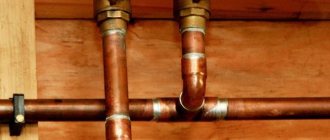
Despite the frequent use of soldering technology for connections, copper pipe is often connected to fittings and fittings using mechanical methods without the use of heat from a gas torch. Moreover, with technological development, mechanical methods of connecting copper pipe assemblies are becoming more and more practical and rational for work. At the moment, connections of copper pipes, fittings and fittings can be made using several proven mechanical methods of detachable connections. Let us consider these options for mechanical assembly without heating in more detail.
Mechanical detachable connections for copper pipes
Plumbing and other practices are marked by the use of a number of methods for creating detachable connections, which are not inferior in reliability and strength to soldered ones. When operating plumbing and other systems where copper pipes are used, there are installation fragments where copper soldering is impossible in principle. For such situations, detachable mechanical connections are precisely applicable:
- Conical flaring.
- Rolling grooves.
- Bonding crimp.
- Insertion by pressing.
Let's consider the technological aspects of each method in case of use for the construction of copper pipeline systems.
Basic information
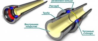
Copper fittings are connecting parts of a pipeline that can have different shapes and purposes. The main functions are connecting, spreading, turning the pipeline. The structure of fittings can differ greatly from each other. A simple example: threaded parts have threads at their ends, which are used for installation. Whereas the crimping parts can be in the form of a monolithic structure without threads at the ends.
Main types of parts depending on their shape:
- Straight connecting parts of constant diameter. They have the form of hollow cylinders, with the help of which two independent sections of the pipeline are connected. A characteristic feature is that the ends of the spare part have the same diameter. Therefore, such spare parts are put on pipes of the same diameter.
- Variable diameter straight connection parts. They also have the form of hollow cylinders for connection. The main feature is that the ends of the spare part have different diameters (example: 30 and 50 millimeters). Therefore, with the help of such parts, pipes that have different diameters are connected.
- Corner Copper Fittings. They look like two cylinders connected to each other at some angle. The angle size is usually 90 degrees, although obtuse and acute angle parts are found. Such spare parts are used if you need to connect several pipeline lines that intersect each other at an angle. They are also used to rotate the pipeline to solve structural problems (for example, a riser runs along the wall from the floor to the ceiling - after this it is turned).
- Adjustable parts. They have the form of parts that have three or more outlets (intersection parts with four adjustable holes are widely used). Such spare parts are used to divide the system into several independent pipelines, as well as to combine individual parts into a single system. In most cases, the exits are located at right angles, although there are also parts with oblique exits. If necessary, a plug can be installed on unused outputs, which can always be removed if necessary.
Method #1: conical flare connection
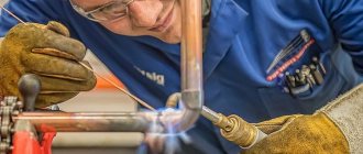
Tubes deployed at the ends - widened towards the end - are considered an acceptable alternative for organizing a connection when the use of soldering is undesirable or impractical.
Water supply systems usually have a connection between a pipe and a socket when connecting, for example, a water flow meter. In addition, copper pipe often has to be connected to brass fittings by socket fitting the end parts of the pipes, flared to a cone at 45°.
A prepared conical mechanical connection of a copper pipe with a fitting for threaded fastening of the mating parts of the assembly. This method is widely used in the installation of air conditioning systems.
This kind of connection of a copper pipe with a fitting (fitting) is carried out using an appropriate tool, through which a conical flaring of the end part of the copper pipe is made. For each pipe size, a tool is used that matches the outside diameter of the copper pipe and the flaring angle—usually 45º.
The tool includes the following elements:
- sliding metal strips with holes of different diameters;
- a yoke equipped with a movable expanding cone;
- clamping screw for sliding bars.
The copper tube is pre-cut with a disk pipe cutter to obtain a smooth end at a right angle relative to the axis of the pipe. Then the nut of the brass fitting is put on the body of the copper pipe and the end part of the copper pipe is flared to the full internal diameter without any residual internal burrs.
Conical flaring (reaming) of the final part of a copper pipe using a special tool set for flaring copper pipes of different diameters
The flaring procedure is simple. Basic moments:
- align the end of the copper pipe exactly along the wide edge of the sliding rod;
- install the yoke along the control side holes exactly above the cut of the copper pipe;
- tighten the halves of the metal clamping strips with a fastening screw;
- Screw the yoke screw with the cone smoothly along the thread until a characteristic click is heard.
It should be noted that not all tools provide a sliding function when full flaring is achieved - they give a characteristic control “click”. Therefore, the flaring process should be additionally monitored.
Device and purpose
In practice, fittings made of copper, bronze and brass are suitable for installing copper pipelines. Only copper couplings and tees are suitable for soldering.
Fittings are produced according to shape:
- Direct.
- Angular.
- Tees and crosses.
- Transitional (for connecting workpieces of different diameters).
- Combined.
The industry produces many combined types of connectors that allow you to easily install pipelines of complex configurations.
By design there are:
- Threaded.
- Compression (collet)
- Press.
- For welding.
Method #2: Roll Groove connection
Pipelines created by connecting with end recesses (rolling grooves) have been practiced for a long time in the construction of sprinkler (irrigation) fire systems. Since 1925, this completely reliable method of connecting pipes has been used on steel and iron lines for heating, ventilation, air conditioning and other systems.
Meanwhile, a similar rolling groove mechanical joining method is also available for copper pipes with a diameter of 50mm to 200mm. The roll groove mechanical connection kit contains:
- couplings,
- gaskets,
- various fittings.
The roll groove mechanical joining system offers a practical alternative to soldering larger diameter copper pipes. Accordingly, the rolling groove method does not require additional heating (use of an open flame), as in the case of soldering with hard or soft solders.
The rolling groove at the end of the copper pipe is one of the main elements of the “rolling groove” connection method. Measuring after rolling determines the appropriate fitting
The connection using the rolling groove method is based on the ductility properties of copper and the increased strength of this metal during cold working. The design involves sealing the clamping system, for which a synthetic elastomer gasket (EPDM - Ethylene Propylene Diene Methylene) and a specially designed clamp are used. A number of manufacturers around the world offer tools for creating connections with rolling grooves - gaskets, clamps, fittings.
Fittings and work clamps with gaskets of various sizes are used in connection designs made using the rolling groove method.
Preparing and performing a rolling groove connection
As with other solderless copper joining processes, proper pipe end preparation is of primary importance to creating a strong, sealed joint. The correct choice of rolling groove connection tool for each type of copper pipe is also obvious. Manufacturer's recommendations must be followed to ensure safe, trouble-free preparation of these types of connections.
Table of permissible pressures and temperatures for this type of connection
| Connection type | Pressure range, kPa | Temperature range, ºC |
| Rolling groove, D = 50.8 – 203.2 mm, type K, L | 0 — 2065 | minus 35 / plus 120 for K minus 30 / plus 80 for L |
| Rolling groove, D = 50.8 – 101.2 mm, D = 50.8 – 203.2 mm type M | 0 — 1725 | minus 35 / plus 120 |
| 0 — 1375 | minus 30 / plus 80 |
Step-by-step process for assembling an assembly using rolling grooves:
- Cut the ends of the copper pipes to size exactly perpendicular to the axis.
- Remove burrs after cutting and chamfer.
- Roll grooves of the required dimensions, as required by the fitting manufacturer.
- Inspect fittings, gaskets, clamps for damage.
- Lubricate the gaskets according to the manufacturer's recommendations.
Before final assembly, inspect the clamping surfaces for cleanliness and the absence of construction debris. Assemble the connection in accordance with the manufacturer's recommendations.
An almost assembled fragment of the assembly using the “rolling groove” method. The elastic gaskets of the clamping bracket are treated with a small amount of lubricant before final seating of the copper pipes
The lug nuts should be finally tightened using the required torque in accordance with the manufacturer's recommendations. After tightening the screws, inspect the clamp area again to ensure that the assembly is assembled correctly.
Testing a Complete Rolled Groove System
Testing of a completed piping system can be carried out by applying air or water pressure to the system. The hydropneumatic method is also not excluded when a relatively high test pressure is used.
However, it should be taken into account that the test pressure value should not exceed the maximum permissible operating pressure specified by the manufacturer of the rolling groove system.
Compression (clamp) fittings
The design of these fittings consists of three elements:
- bronze or brass body;
- metal copper or brass clamping ring;
- union nut.
The clamping ring is located inside and is pressed against the fitting body with a union nut. The connections are installed using a flat wrench, and the number of turns for tightening is different for each type of fitting. Compression clamp fittings are used in water supply, gas supply and heating systems, as well as during repair work and in emergency situations due to the speed and ease of installation and the availability of the tools used, wrenches of different diameters. Another advantage of these fittings is that they can be reused.
Method #3: Press-connect connection
Connecting copper pipe and copper alloy fittings using the crimp bonding method is fast, economical and does not require soldering technology. The Press-connect method originated in Europe in the late 1950s and is still used successfully today. Since the late 1990s, this connection method has spread throughout the world.
Structural view of a mechanical bonding crimp connection (“press-connect”), where high tightness is achieved through the use of an elastomer seal
The practice of using a bonding crimp connection shows satisfactory results. As in the previous (#2) option, the effect of plasticity and pronounced strength of copper during cold working is used here. The bonding crimp connection requires the presence of:
- special fitting,
- elastomeric gasket,
- crimping tool,
- special sponges.
Typical pressure and temperature ranges for bonded crimp connections are shown in the table below:
| Connection type | Pressure range, kPa | Temperature range, ºC |
| Crimp binder, D = 12.7 – 101.6 mm | 0 – 1375 | minus 18 / plus 120 |
| High pressure crimp binder, D = 6.35 – 31.75 mm | 0 — 4826 | Minus 32 / plus 150 |
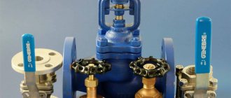
Threaded elements
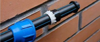
They are simple and durable, their design does not require modification. The best option for these parts are brass fittings. They are characterized by increased resistance to corrosion, and are installed in those places of the pipeline where fixation to the wall is required.
IMPORTANT! It is not recommended to combine such fittings with pipelines made of plastic, metal-plastic and copper. Because during twisting, this part can easily crush the workpiece made from the specified materials.
Step-by-step creation of a bonding crimp connection
The copper pipe for the bonding crimp connection should be carefully inspected for dents, deep scratches, dirt, oil, grease, and other defects on the outside and inside. If a slight ovality of the copper pipe is detected in the crimp area, the defect must be corrected with an appropriate tool.
Step 1: adjusting the workpiece to size
Preparatory process before creating a unit using the “press-connect” method:
Accurately adjust the length of the copper pipe, taking into account the emphasis on the base of the bowl of the connecting unit. Cut the workpiece to size using a disc pipe cutter, keeping the end edge perpendicular. Remove burrs and chamfer the end part of the copper pipe to eliminate the possibility of damage to the gasket when inserting the copper pipe into the fitting.
Step 2: Mark insertion depth and select jaws
Selecting the appropriate cam mechanism and marking the depth of insertion of the end part during the application of the bond crimp method
fig8 Selecting the appropriate cam mechanism and marking the depth of insertion of the end part during the application of the bond crimp method
Check the fitting for use in the assembly, make sure that the sealing gasket is intact and is correctly positioned. The insertion depth of the copper pipe end into the fitting must be marked on the surface before inserting the copper pipe into the fitting. Select the appropriate size of pressing jaw and insert into the pressing tool.
Step 3: joining the copper pipe with the fitting and crimping process
Using a crimping tool at the final stage of creating a connection by mechanical pressing
The copper pipe should be inserted all the way inside the fitting, aligned until the pressing jaws are applied to the fitting. Place the clamping jaws on the fitting collar at a 90° angle (perpendicular) to the center line of the copper pipe. Activate the pressing tool trigger.
Upon completion of the pressing cycle, loosen the clamping jaws, remove the tool and visually inspect the seam, focusing on the previously placed mark on the surface of the copper pipe.
Self-locking fittings
Self-locking fittings are the newest type of copper fittings and are classified as crimp fittings. Typically such a fitting is:
- brass or bronze body;
- steel toothed ring (lobe washer);
- centered plastic washer.
The connection is sealed with an EPDM O-ring.
Diagram of the device of a self-locking push fitting.
The name “self-fixing” is due to the ability of such fittings to fix copper pipes without the help of tools or additional actions: a strong connection of pipes is achieved by simply inserting it into the fitting. This connection is dismountable; the teeth of the lock washer are pressed out thanks to a special puller key for the polymer sleeve located under the fitting nut. This allows the fittings to be used multiple times. Like a compression connection, a self-locking connection requires periodic inspection and maintenance.
High pressure crimp connections
Advances in bonded crimp technology and the development of O-ring materials are allowing bonded crimp connections to be used for high pressure applications. However, high pressure systems require a slightly different jaw configuration.
The result of manufacturing a connecting unit using the 360º double crimping technique
Bonded crimp connections for low pressure piping, process piping and non-medical compressed gas lines use a single standard hexagonal pressing shape.
Higher pressure bonding crimp connections require the use of specially designed press fittings and clamping jaws to provide a 360° double crimp on the fitting.
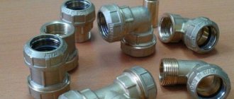
Advantages of press fittings
Types of press fittings.
One of the main advantages of press fittings is the possibility of quick and high-quality installation without the use of open flames or electric heaters. They can be used everywhere in facilities where the use of open flame burners is prohibited, inside various containers, tanks, tanks. But the price of press fittings, due to the complicated part, is higher than the cost of solder fittings.
To crimp them, you need electric or hydraulic presses with sets of pliers of different diameters, having different profiles: V, SV, M, SA and others. The materials for the manufacture of press fittings are the same as for the others: copper, brass, bronze.
Application areas of press fittings:
- gas supply;
- transportation of compressed air;
- transportation of oils and petroleum products;
- transportation of liquid chemical reagents;
- piping for water supply and heating;
- air conditioning and fire extinguishing systems.
All fittings discussed in this section are used to connect solid and semi-solid pipes.