Welding is a reliable joining method, but sometimes welds need additional reinforcement to make them stronger and more stable. And the method of strengthening will depend on what type of welding is made, therefore, when developing welding skills, it is important to simultaneously learn to strengthen it, no matter where it is and what size it is. Read more about what weld reinforcement is, as well as how to implement it correctly, below.
Features of strengthening welds
Reinforcing regular welds is not that difficult, but when it comes to fillet joints, they will require a special approach.
The task will be complicated by the fact that often when strengthening a seam by increasing its length it is necessary to use additional overlaps, ribs, overlays and other structures. And they are selected individually according to the size of the welding area, its location, the material that was welded, the characteristics of the leg, etc.
Diagram of a weld with and without reinforcement
Main types of butt welds:
Figure 529.1 . Main types of butt welds.
According to the design option (side view of the weld):
a) Straight line , coinciding with the cross-section of the element under consideration.
b) Oblique . It is done in cases where, according to calculations, a straight seam is not enough to ensure strength.
As can be seen from the figure, butt welds can be used to connect parts of different thicknesses.
According to the shape of the seam (sectional view):
c) Without edges .
d) V-shaped .
e) X-shaped .
e) K-shaped .
As can be seen from the figure, the choice of one or another weld shape depends on the thickness of the parts being welded.
1.1. Geometric characteristics of butt welds
Also, Figure 529.1 shows the main geometric characteristics of welds necessary for calculating butt welds for strength:
t is the thickness of the seam, cm.
In the general case, when the thicknesses of the parts being welded are the same, then the thickness of the seam is equal to the thickness of the parts being welded. If the thicknesses of the parts being welded are different, then the thickness of the seam is considered to be the smallest thickness of the parts being welded. The shape of the seam (sectional view) does not affect the determination of the thickness of the butt weld in any way for the reason that when calculating the strength of the weld material, sections with the smallest area are considered. In this case, the sections at the fusion boundary will have the smallest area.
lw - seam length, cm.
Since with any welding technology there is a lack of penetration at the beginning and end of the seam, taking this into account, the calculated length of the seam is accepted (according to SP 16.13330.2011 “Steel Structures”):
lw = h - 2t (529.1.1)
or
lw = h (529.1.2) - when the ends of the seam extend beyond the joint
where h is the height of the parts being welded.
Notes:
1. In figure (529.1) all dimensions are given in millimeters for the special case when t = 5 mm. Previously, this was a common case, but now, as we see, the requirements have changed.
2. For further calculations, it is better to immediately convert all dimensions into centimeters. However, this is not of fundamental importance.
What does the term seam reinforcement remove mean?
It’s difficult to immediately understand from the name what this means – “seam reinforcement”. So, in the specialized literature this term is deciphered as a part of the deposited metal that forms a convexity.
But the designation in the drawing “remove seam reinforcement” (open circle on a horizontal line, GOST 2.312-72 ESKD) suggests that this same tubercle needs to be eliminated. Most often it is cleaned with a grinder. But you should not forget that reinforcements on corner and butt welded areas must not be removed in the same way. On corner joints, for example, the leg should remain, although on butt joints it is expected to remove everything that protrudes above the surface of the materials being joined.
Designation for removing weld reinforcement
Removing the reinforcement of a welded joint can also be marked in small letters of the English alphabet, where:
- a is an increase in length, suggesting a frontal overlap of the part.
- b - indicates an increase in the working length (or height) of the leg at which the fillet weld is located.
- c is the internal corner cladding, measured in height, taking into account the presence of additional technological elements, surfacing or special parameters of the frontal parts.
The notation system allows you to better understand not only the features of cooking, but also the materials, as well as the structures made from them, with which you will work.
Removing the weld: 1 - parts to be welded; 2 - weld; 3 - material removed during processing
STRUCTURAL ELEMENTS OF WELDED JOINTS IN MANUAL ARC WELDING
Due to the importance of proper preparation of welded edges from the point of view of quality, efficiency, strength and performance of the welded joint, state standards have been created for the preparation of edges for welding. The standards regulate the shape and structural elements of cutting and assembling edges for welding and the dimensions of finished welds.
GOST 5264-80 “Seams of welded joints. Manual electric arc welding. Basic types, structural elements and dimensions" and GOST 11534-75 "Manual arc welding. Welded connections at acute and obtuse angles. Basic types, structural elements and dimensions” regulate the structural elements of edge preparation and the dimensions of the seams made during manual arc welding with a metal electrode in all spatial positions.
It is necessary to note some features of the application of standards. Due to their technological features, various methods of electric fusion welding make it possible to obtain different maximum penetration depths. By varying the basic parameters of the welding mode and the design types of edge preparation, it is possible to increase or decrease the depth of penetration and other dimensions of the weld.
For this reason, the mentioned standards regulating the structural elements of edge preparation take into account the possibility of varying the welding current, voltage, electrode wire diameter (current density) and welding speed. In cases where the welding process requires the use of high currents, high current densities and heat concentrations, increased bluntness, smaller groove angles and gap sizes are possible.
In manual arc welding, factors such as welding current, welding speed and arc voltage vary within small limits.
To ensure through penetration of the edges of the product when welding one-sided butt or fillet welds with sheet thicknesses over 4 mm, welding must be carried out along pre-cut edges. When manually welding, welders cannot significantly change the depth of penetration of the base metal, but by changing the amplitude of the transverse vibrations of the electrode, they can significantly change the width of the weld.
For sheet thicknesses of 9 - 100 mm, GOST 5264-80 for butt joints requires mandatory cutting of edges and a gap, which vary in size depending on the thickness of the metal and the type of joint.
In all cases, using edge preparation standards, you should choose those types of grooves that provide the least volume and cost of edge preparation work, volume and weight of deposited metal, full thickness penetration, smooth mating shape of the outer part of the weld and minimal angular deformations.
The quality of welded joints and the efficiency of the welding process are greatly influenced by the cleanliness of the edges and the adjacent surface of the base metal, the accuracy of edge preparation and assembly for welding. Blanks for parts to be welded should be made from pre-straightened and cleaned metal. Cutting of parts and preparation of edges is carried out by mechanical processing (on press shears, edge planers and milling machines), oxygen gas and plasma cutting, etc. After using thermal cutting methods, the edges are cleaned of burr, scale, etc. (grinding wheels, metal brushes, etc. etc.).
In some cases, when welding high-alloy steels, the base metal in the heat-affected zone after cutting is also removed mechanically. Before assembling the edge, adjacent areas of the base metal (40 mm from the edge) must be cleaned of oil, rust and other contaminants using wire brushes, shot blasting or chemical etching. The parts are assembled using tack welds (short seams) 20-30 mm long or in special assembly devices.
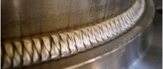
Reinforcement of butt seams
Strengthening butt welding is complicated by the fact that most often its strengthening can lead to damage to the joint. For example, if the butt seam is made along the entire length or height of the metal components, then no reinforcement can be done at all. Surfacing will create excessive concentration at the melting point, due to which the surfacing can not only deteriorate, but also completely collapse. The thing is that the height of such welds is determined only by the elements being joined and taking into account the structure of the bead of the connection itself. This roller is the protrusion.
If the butt welding still needs to be processed, then you first need to relieve the tension with abrasive tools. After this, the area of the overlays is calculated, with the help of which the seam will be strengthened.
Geometric characteristics
As mentioned above, the geometry of the seams depends on the type of connection. The main geometric dimensions of the sections of butt and fillet welds are presented in the following figure:
Read also: Do-it-yourself natural draft smoke generator
- where S is the thickness of the parts;
- e – width of the weld;
- g – convexity;
- m – concavity;
- h – penetration depth;
- t – weld thickness;
- b – gap in the connection;
- k – fillet weld leg;
- p – height;
- a – thickness.
The geometric dimensions are affected by the type of connection and the thickness of the products being welded. These indicators are shown in the following table.
From the information presented it is clear that all geometric dimensions of welds and parts being connected are interconnected. The length of these elements of welded structures stands out. It depends only on the load on the connection and is completely independent of the geometry of the seam section. The minimum length of the weld must ensure the strength of the connection when the maximum total load is exceeded by 20%. Products are often welded along the entire length of the contact, but in many cases welding is performed in short sections to ensure the necessary strength of the connection. For building structures, the calculation of the length of the weld according to SNiP II-23-81 is carried out based on these criteria.
Calculation of butt weld geometry
The method for checking seams for this type is fully described in the following regulatory documents: SNiP II-23-81 clause 11.1 and SP 16.13330.2011 clause 14.1.14. These documents present different calculation methods, but all of them are derived from the following mathematical formula:
- where N is the maximum tensile or compressive force;
- t – minimum thickness of welded parts;
- lw – seam length;
- Rwy – load resistance;
- γс – tabular coefficient.
With this type of connection, it is welded over the entire length of the contact, therefore the length of the seam is equal to the length of the joints of the parts being welded, reduced by 2t, twice the thickness of the metal. The width of the seam depends on the shape of the edges and the thickness of the parts. Schemes of design options for butt joints are shown in the following figures.
If during welding work materials are used in accordance with Appendix 2 of SNiP II-23-81, no calculations are made, only visual quality control of the connections made is carried out.
Calculation of fillet weld geometry
Calculation of the geometric dimensions of fillet welds under the influence of a load passing along the axis of the center of gravity is carried out along the selected section, the most dangerous in this connection. This may be a calculation based on the cross-section of the weld metal or the fusion boundaries of materials. The figure below shows both sections.
In this type of welded joints, stresses of various types act, but the dominant load is the shear force. Fillet welds are checked using the following formulas.
where N is the maximum tensile or compressive force; βf and βz – tabular coefficients for steel; kf – weld leg length; lw – length; Rwf – design shear resistance; Rwz – the same but in the fusion zone; γс – tabular coefficient of operating conditions; γwf and γwz – the same, but for different operating conditions.
The main geometric characteristic of all fillet welds is the size of their leg, i.e. the thickness along the fusion boundaries. The size of the leg depends on the thickness of the parts, material and welding method. You can select the value of this geometric parameter in the table below.
For steel structures with maximum material flow characteristics above 590 N/sq.mm or a thickness of connected parts above 80 mm, the value of the minimum leg size should be taken in special specifications.
For structures of the fourth group, the size of the fillet weld leg should be reduced by 1 mm for parts with a thickness of no more than 40 mm and reduced by 2 mm for parts thicker than 40 mm.”
Tools for checking seam dimensions
A weld geometric parameters meter is a specialized tool that can be used to measure the main characteristics of these elements of welded structures. Among the variety of such measuring instruments, the following groups of products can be distinguished: templates, universal meters and devices specialized in measuring one parameter. A professional welder’s kit includes several such tools that allow you to measure both parts prepared for welding and the weld itself.
Main types of welds and their brief characteristics
GOST describes three types of welded joints of steel pipelines and provides their symbols. This:
Within each type, the standard distinguishes various subtypes depending on different parameters. These include the diameter and thickness of the pipe being welded, the type of weld, the number of sides of the weld, the configuration for the gasket and the possibility of its removal, the presence of bevel of the edges (bevel of one or two edges), the shape of the cross-section of the edges or suture material, and the welding method.
According to GOST 16037-80, when connecting a pipeline, welding under shielding gas (argon), submerged arc and gas can be used. When working in an atmosphere of protective gases, the use of consumable and non-consumable electrodes is allowed.
To determine welding technological parameters, GOST 16037-80 recommends taking into account the following parameters (the document contains specific values depending on the type of welding):
All specified parameters are not relevant for all types of seams.
During the work, various types of welded joints are used depending on the specifics of the situation. For welding circular joints of pipes according to GOST, butt joints with the designation C1-C53 are used. This type of seams, in turn, can be made as one-sided or double-sided, straight and with rounded beveled edges.
Single-sided seams may include a removable or retained lining, as well as a fusible insert.
When connecting sectors at turns, the connections can be made with beveled edges and have the symbol C54-C55.
When connecting a flange to a pipeline, the designation C56 is used.
Fillet welds are prescribed in the standard as U5-U21, lap welds - H1-H4.
Cutting pipes for welding
GOST 16037-80 regulates not only the types of welded joints of steel pipelines (butt, lap and corner), but also the characteristics of preparatory measures taking into account the type.
Before carrying out welding work, it is necessary to carry out preparatory measures. These include:
Cutting involves mechanical processing of the edge. During pipeline installation, cutting is carried out using special machines. When carrying out repairs, cutting using angle grinders is allowed.
Edge cutting must be performed when the thickness of the workpieces for welding is from 4 mm. For corner joints, bevel one or both edges at a 45-degree angle.
Joints on steel pipelines can be rotary or fixed. When welding a pipeline, it is recommended to use the first type, since they allow the welder to take the most advantageous lower position. The edges are cut along the entire perimeter.
With a butt connection, the difference between the wall thicknesses cannot be more than 10% and exceed 3 mm.
Before installation, the edges and heat-affected zone are also processed to 20-30 mm. It is cleaned of mechanical impurities, corrosion traces and oil and fat stains.
Before electric arc welding, the ends of the pipes must be tacked to each other. For pipe diameters not exceeding 300 mm, 4 tacks are made. If it exceeds 300 mm, then tacks are made evenly every 200-300 mm.
Welding of pipes with a thickness of more than 12 mm is carried out in three steps (penetrations).
If thick pipe blanks are connected, then the formed seam must be made thicker than the part itself. To form a connection with the specified parameters, you need to cut the edges after chamfering. At the same time, the electrode is provided with access for high-quality welding of the seam.
When calculating technological cutting parameters, special attention should be paid to the correctness of the calculation and compliance with certain cutting values. This reduces labor intensity, allows you to use materials economically and control costs.
When preparing joints, the type of chamfer depends on the thickness of the workpieces: with a thickness of 3-25 mm, a one-sided chamfer is used, with a thickness of 26-60 mm, a double-sided chamfer. For corner joints, the following boundaries are set: for values up to 20 mm - one-sided, up to 50 mm - two-sided.
Based on the geometric shape of the profile, the following subtypes of cutting are distinguished:
If the pipe has a thickness of over 60 mm, then special shapes are used (in particular, ledges and complex curved profiles).
Gas cutters and mechanical processing are used for cutting. The first method has certain limitations and disadvantages: it has low qualities. The highest accuracy is ensured by milling; for large-diameter pipes, special trimming machines or grinders can be used.
Thus, GOSTs for welding activities are an important document that regulates the conditions for preparing and carrying out welding work. GOST 16037-80 defines methods for welding steel pipelines, types of connections, cutting methods and structural elements for each type. Compliance with the recommended parameters extends the service life of pipelines, ensures durability, strength and tightness of seams.
Source
Geometric dimensions of the weld
A crystallized piece of molten metal formed at the junction of two metal parts or structures is a classic welding seam, which has certain geometric dimensions both in cross-section and in length. They depend on the type of connection, the welding method, the geometry of the cutting of the end edges of the products being joined and some other factors. These elements of welded parts are divided into two types: butt and corner. They should not be confused with the types of welding joints that are classified as butt, fillet, tee, and lap joints.
In all such structures there are working seams, which are subject to the main loads of the connection. The strength of the entire structure as a whole depends on the correct calculation of these connection elements. The quality of welding is influenced by many factors, including geometric characteristics such as width, length, concavity, convexity and other features of joining parts. For parts connected at right angles, the main geometric parameter is the size of the weld leg, on which the welding strength depends.
What GOST 16037-80 regulates
GOST 16037-80 was approved for use by the Decree of the USSR State Committee for Standards in the 1980s. It came into force in July 1981 and is still in force today. GOST replaced the previously existing standard in this industry 16037-70. In December 1990, the last and only changes were made to the document.
The scope of GOST regulation is welded joints of steel pipelines. It is required for use:
The mandatory nature of the standard means that all welders who begin welding steel pipes must take into account the provisions of the standard. Welded joints that are used for the production of pipes from strip and sheet material are excluded from the scope of regulation of the document.
When installing pipeline systems, one of the most common methods is manual welding, the production requirements for which are specified in GOST 16037-80. The full text of the document can be found here.
The safety of operation of pipeline systems largely depends on the quality of joints and seams.
With strict adherence to the requirements of the standard during the design and formation of the technological process and the actual execution of pipeline welds, the required level of quality is ensured.