How to weld a channel without losing the strength of the seam
In construction, a channel is used to increase the load on the supporting and load-bearing structures of a building. Often channels are connected to each other to increase their load-bearing area. Of course, a better method of welding for connecting channels has not yet been invented, so this is what we will talk about.
Welding channels is a critical step, since the safety of the entire structure depends on the strength of the connection. Therefore, when carrying out this process, welders adhere to strict rules and GOST.
Common connections
Butt welding
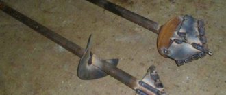
Channel butt welding is the favorite connection of all beginners.
It is used for practice or for welding non-critical structures. Can be done both from the front and from the inside. But when welding from the inside, you need to make sure that there are no lacks of penetration. Also, a seam can be formed only on one side, but in this case it is necessary to weld the root of the seam. If the thickness of the channel walls exceeds 6 millimeters, then it is necessary to cut the edges. The cutting can be V or X-shaped. The optimal angle is 30 degrees if the thickness is no more than 12 millimeters.
Let's start welding. To begin, join two channels with the walls facing each other. Docking should be as precise as possible; it is better to do it not by eye, but with the help of a special centralizer. The gap between two channels should not exceed 3 millimeters. To prevent the workpieces from moving in different directions during welding, you need to make a temporary tack. The tack is welded to both parts using weld points.
The seam must be drawn from the middle of the channels to the edges. Please note that this connection is not very reliable. To strengthen it, you can use overlays. We'll talk about this in more detail later.
Welding using pads
Welding channels with overlays is already more reliable than conventional butt welding. This is also proven by the fact that the gap between the channels can reach up to 8 millimeters. The plate itself must be placed on the side of the welded joint. The overlay is selected based on the thickness and size of the channels. The larger and thicker the channel, the stronger the lining should be. When welding, it is necessary to weld both sides of the lining.
Now more details. To choose an overlay you need to know the approximate dimensions of the channels that you are going to weld. We recommend dividing the channel length by 5. This will give you the recommended overlay length. The thickness of the overlay should be the same as the thickness of the channel. There should be two pads in total. From the inside and from the outside. In this case, the outer lining should be longer than the inner one.
Connection inwards
Sometimes channels are welded with “shelves” inward. The technique is the same as for butt welding, only there is either no gap or it is very small. Inward welding is more difficult to perform than butt welding. So this connection could be next in your educational practice.
Welding is performed as follows. Prepare the metal thoroughly before welding. Do not use an angle grinder, otherwise the connection will not be strong. Join the two channels horizontally and symmetrically. Secure them with clamps. It is advisable to make a seam with grooved edges, but sometimes a small gap is allowed. Welding is performed from the middle of the channel to its edges.
The main disadvantage of this method of welding channels is the need to work in ideal conditions. You will not be able to weld in hard-to-reach places. To ensure a high-quality seam, you need to cook it in a strictly horizontal lower position. If you cook under other conditions, then you will simply waste time, effort and components. It is more logical to weld end-to-end or using overlays.
In general, this connection is used infrequently. But if you have the opportunity to cook in a lower horizontal position, and you choose the place of butt welding and welding inside, then we recommend choosing the second option. It is still more reliable.
Offset connection
Offset connection of channels is a complex job that is performed by a whole team of welders. Such a connection is necessary in cases where it is necessary to weld different structures from channels, and at the same time these channels have different sizes.
Welding should begin from those places where the channels are thickest. It is necessary to combine different connections: end-to-end, corner, and longitudinal. Moreover, each connection will have its own nuances. Butt joints are performed simply and without problems, but corner joints must be performed by two welders at once. And when making longitudinal seams, they cannot be formed to the end of the channel.
Note
All the connections and methods that we described above are suitable for welding most structures that use channels. However, you don't necessarily need to use only one connection method. You can combine, for example, butt joints and joints with overlays in different parts of the metal structure. The most important thing is to calculate all the loads. After all, sometimes in some nodes the connection should not be “forever”.
But whatever method you choose, always remember that you need to follow the sequence of actions. You cannot cut the edges first, and then clean the metal, and then cook it. All stages must be performed in accordance with technology. If GOST standards indicate that the metal is cleaned first, and then everything else, then follow these rules. And in general, GOSTs are your best friends. After all, they spell out all the features that need to be taken into account in the work. As we already wrote above, it is recommended to start the seam from the middle of the channel to its edges. In this case, the thickest part of the channel is cooked first. To be more aware of the result you want to get after completing the work, perceive the welded joint as a defect. Yes exactly. After all, the seam in any case deteriorates the strength of the entire structure, albeit slightly. Yes, even the best quality connection can reduce the strength by up to 10%. Therefore, try to do the work so that the strength decreases by only a couple of percent. This way you will achieve a good result.
As for the welding mode, this is a very broad and complex topic. The current strength and other parameters must be selected based on the thickness and type of metal. If you weld using electric welding, then monitor the speed of seam formation. The optimal speed is 20 meters per hour.
What do an I-beam, a channel and an angle have in common?
Butt welding of I-beams to each other
The first thing that unites these profiles is the material from which they are made. The steel used is ordinary carbon, high-quality structural, and low-alloy.
Structural steel is preferably used in hot-rolled production. For profiles intended to work in more severe conditions, low-alloy steel is used. Products made from it can withstand temperatures from -70 to +450 degrees and significant mechanical loads. To protect against rust, stainless or carbon galvanized steel is used. Alloy steel is usually not used for shaped rolled products.
The second common feature of shaped steel is the production method. It can be made by welding, hot and cold rolling. In addition, shaped profiles are obtained by bending blanks. How the steel profile was obtained (welded or bent) can be determined simply by looking at it: for bent products the corner will be rounded, but for rolled products it will be clear.
The peculiarity of shaped metal products is that nothing is made from it itself. This is a ready-made product that goes straight into use. While flat and long products are used for the production of other types of rolled metal.
Manufacturing Features
Channels, as a supporting element of many structures, are in great demand. They are not only made from different types of steel, including stainless steel, but also use different manufacturing technologies.
Channel 16p
The technology can be hot rolled or cold rolled. There are differences in the geometry of the shelves. In some products, the edges of the shelves inside are parallel to each other, in others they are made obliquely.
Regardless of the design of the shelves, the range of steel channels is characterized by high rigidity and low weight. These qualities make it possible to widely use them in construction and other industries to create durable structures that can withstand heavy loads.
The process of manufacturing metal products occurs in stages. The appearance and characteristics of finished products depend on the technological features of a particular production. The sequence of work depends on the profiling method:
- with the continuous method, the molded piece of the required length is cut by the machine itself;
- with piece profiling, the workpieces are first cut and then processed in a unit.
In any case, the output should be a high-quality product that complies with GOST 11475. An equal-flange bent profile must be manufactured in accordance with GOST 8278-83, an unequal-flange profile - in accordance with GOST 8281-80.
Separately about cutting pipes for welding
Welding of metal structures
Cutting is the operation of forming beveled edges on a workpiece. Their presence is required on parts of large thickness for the following purposes:
- provide easy access to the root of the weld for the welder’s tool;
- enable high-quality welding of elements throughout their entire thickness.
Cutting increases material consumption due to an increase in the weld zone. Minimum indicators are observed if edge cutting is not performed.
Before preparing the pipe ends for cutting, be sure to clean them. The procedure takes place in 2 stages:
- A layer of rust, oxides, and other contaminants is removed mechanically. It is carried out with abrasive tools of varying degrees of grain, both manually and using angle grinders.
- Chemical cleaning is performed to degrease the area where the seam will be and to remove other contaminants. Organic solvents are most often used, but in some cases acid etching is used.
Edges can be single-sided or double-sided. According to the shape of the bevel, they are divided into V, X, and U-shaped.
Correctly performed cutting of pipes will ensure minimization of internal stresses in the structure after completion of the work.
Channel welding methods and their features
Metal beam joints: basic connection methods
Before you start welding, it is necessary to properly heat the metal. The position of the channels must be correct and convenient for welding, otherwise this will lead to a weakening of the strength of the heat-affected zone of uneven melting.
Arc welding:
- connections are made overlapping;
- Before working with electrodes, it is advisable to carefully study the topic. For example, the electrode must be calcined in a special furnace;
- the metal must be prepared for work in accordance with GOST;
- For work, it is recommended to use a short arc with the following parameters: average power and reverse polarity;
- welding with straight polarity is easier, but you need to make sure that the weld pool does not overtake the arc;
- After work, you need to check the structure for internal defects.
Butt welding:
- sufficient penetration depth is left for welding;
- perform welding on both sides;
- if the thickness of the channel flanges is less than 6 mm, then there is no need to bevel the edges;
- if the thickness of the shelves is up to 12 mm, then the bevel is made at an angle of 30 degrees, if more than 12 mm, the bevel is made from the inside and at an obtuse angle of any degree.
- process execution conditions;
- length of the welded joint;
- type of load on connections;
- type of channel and its main parameter – thickness;
- load that the structure will experience.
Technologies used
There are several technologies suitable for high-quality channel welding. But we will tell you about the most convenient and frequently used one, in our opinion.
Arc welding
Electric arc technology is the undisputed leader. And all because manufacturers offer a wide range of electrodes for working with a wide variety of types of metals. In addition, electric arc welding can be carried out in the most difficult to reach places, including at heights. Of course, provided that the welding machine is compact and can be hung on your shoulder.
Requirements for channel welding
- First of all, the thick elements of the channel (flanges) are welded, after which they begin to weld the thin wall.
- You should not weld along the inner edges of the shelves and in the corners of the connection between the shelf and the wall of the channel, as this will only lead to a weakening of the structure.
- The junction of two channels should have a gap of 2 - 3 mm to prevent the formation of a “slide” during welding, after stripping which the welding seam will weaken.
- If the design does not have special requirements for strength and reliability, but speed and ease of performing the work are important, then the channels can be joined end-to-end with double-sided welding (without overlays).
- The edges of the end along which the joining occurs are formed in a V- or X-shape (for a thin or thick profile, respectively) at an angle of 30° - 60°.
- There should be no horizontal or vertical fractures at the junction of the parts being connected.
- Docking can be done using sheet overlays, which must be positioned symmetrically relative to the longitudinal axis of the section.
- The zone of the welded joint without overlays is at least 5% (in some cases up to 20%) weaker than the strength of the channel, which must be taken into account in design calculations.
- When using overlays, the joint between the ends of the channels does not need to be welded, so its width can reach 50 mm.
It is recommended to completely weld the linings along the abutment contour, which will prevent moisture from penetrating between them and the channel, leading to crevice corrosion. If this is not possible, the gap between the lining and the channel is filled with anti-corrosion material. To increase the density of their contact, clamps should be used.
The edges of the overlays on the channel flanges must be parallel to the edges of the flanges. When welding a joint, the linings on the shelves are installed only after the seam has been cleaned and its quality has been checked.
Welding beam joints using submerged arc machines.
Let's say a few words about automatic welding of joints. If the beam is welded under submerged arc using automatic welding machines, then different techniques may be used, just as the sequence may differ.
Welding can be carried out with an inclined electrode, which allows you to make two seams at the same time. On the other hand, this method also has disadvantages. When the electrode is tilted, the risk of cutting off the flanges or walls of the beam increases.
In addition, seams can be performed in a position called by specialists, “boat”. This creates better conditions for seam formation, penetration, etc. However, among the disadvantages of this method is the need to rotate the product after each welded joint. This disadvantage is solved by using special positioners-tilters.
The process of welding beam joints requires careful preparation, carrying out and checking calculations of moments of inertia, bending moment, etc.
It is important to follow the beam welding technology, the incorrectness of which can affect the future metal structure as a whole
Welding channels without loss of joint strength
Any welded connection weakens the structure and its individual components. Therefore, in construction, to reduce welded joints under increased loads on the support beams of load-bearing structures, it is customary to use channel and I-rolled metal products. Welding a channel during installation of load-bearing parts of a structure is a particularly important stage, but it often causes difficulties and the inability to comply with strict welding rules (GOST).
General information about the channel
A steel channel is a metal product that has a U-shaped cross-section profile. This design makes it possible to obtain high structural characteristics with minimal consumption of material and metal. The methods of manufacturing channels (by bending on a special machine or by hot rolling) do not affect the choice of welding technique when connecting them, but only on the general strength characteristics.
The main advantages of the channel are aimed at strengthening individual structural units and are:
- Able to withstand large axial loads.
- High resistance to bending under central load.
- Possibility of connection without welding.
And also these same advantages are also disadvantages when welding channels.
Currently, five types of channels are produced:
- special;
- with shelves of different sizes;
- equal-flange;
- with a certain slope of the shelf edges;
- with parallel edges of the shelves.
The greatest joint strength can be achieved by welding equal-flange channels with parallel flange edges. They are the most in demand in the construction industry.
Difficulties in connecting channels
Channels have proven themselves well for prefabricated metal structures, but the smallest errors in their connection cause a critical violation of the strength of the entire structure. Each welded joint itself weakens the strength of the metal structure by 5-7%, despite the fact that the weld metal has higher strength characteristics than the metal of the main part.
The problem lies in the welding technique itself, in the correct preheating of the metal and in the experience of the welder. An inconvenient position when assembling some units, as well as incorrectly selected seams, leads to the fact that the heat-affected welding zone (zone of uneven melting) loses up to 20% of its strength. These are the most vulnerable joints and there are two of them for each weld, on both sides. GOST provides for the most common node connections, but not all.
- All recommended standards according to GOST cannot be neglected.
- Welding of channels according to GOST is much stronger, even with additional reinforcement of the structure.
- All additional linings after butt welding must be performed exclusively on the outside of the channels.
- Welding in the inner corners of the channel only weakens the overall structure, so welding in the inner corners, as well as inside the channel itself, is not advisable.
- You can weld not only according to GOST, as this is sometimes inconvenient, but also based on recommendations.
Arc welding
The peculiarities of using electrodes and the possibility of selecting them according to their main characteristics make electric arc welding the most preferable for connecting channels. The highest quality seam is obtained using UONI electrodes, but there are some peculiarities of their use.
- It is advisable to make overlapped connections.
- Working with these electrodes requires experience.
- Before starting work, the electrode should be calcined in a special oven at a temperature of 250 0C for an hour.
- The metal must be carefully prepared in accordance with GOST.
- For welding it is necessary to use a short arc of medium power with reverse polarity.
- It is easier to weld with straight polarity, since the electrode burns more slowly, but then you need to monitor the weld pool. She must not overtake the arc.
- With such a connection, it is imperative to check for internal defects.
The welding mode itself and the speed of the seam depend on the selected type of connection, but the most optimal for manual welding is 20 m/h.
Gas welding
When connecting channels, the use of oxygen-gas welding is most often completely abandoned. The heating temperature and a large heating zone, and, accordingly, an even larger heat-affected weak heating zone, do not favor the choice of this joining method. Negative thermal effects, as well as overheating of the weld area, lead to unnecessary internal stress in the metal and severe deformation of the overall structure (beam).
Beam markings and dimensions
According to GOST wide-flange I-beam 8239-89, the size of the product is determined by the height of its wall. How to understand this? For example, if we take profile number 14, then its height (distance between the shelf) will be 140 mm, which means that beam number 55 will have a height of 550 mm. But these are not all the parameters that are specified in GOST and characterize the material. Each beam number has its own dimensions, cross-sectional area, mass and values for the axes. Beams can be distinguished by the following parameters:
- shelf arrangement. Products can be parallel or have a slope of internal edges;
- manufacturing principle. Beams are made welded from steel sheets and hot-rolled. Hot rolled are a monolithic metal structure;
- precision production. Mark “B” denotes I-beams made with increased precision, and mark “B” indicates normal precision.
First, let's look at the parameters of a hot-rolled I-beam; its dimensions and cross-section are indicated in the table in accordance with GOST 8239-72:
Additions:
- The weight of 1 m of the beam and its cross-sectional area were calculated based on the nominal dimensions, with a steel density of 7850 kg/m3.
- The values in the table provided above are defined as follows: “I” indicates the moment of inertia, “W” indicates the moment of resistance, “S” indicates the static half-section moment. As for the value of “i”, it indicates the radius of gyration.
GOST also specifies maximum deviations of weight and dimensions. They can be seen in this photo:
The designations are deciphered as follows:
- b1 – width of the part that is shortened;
- b2 – width of the part that is extended;
- ∆ – skew level;
- f – deflection level at the I-beam wall.
It is considered normal to consider metal I-beams that have a slope of edges inside from 6 to 12%. According to their purpose, they can be divided into two types: ordinary and special. The range of I-beams is specified in GOST 19425-74. It is suitable as overhead track beams and can also be used to reinforce mine shafts. In the first case, this is the “M” series, in the second, the “C” series.
GOST 26020-83 specifies the production of I-beams with parallel edges located inside. Depending on the features, the following types of products can be noted:
- Beam shelves, the height of which reaches 1 m, and the width of the shelves is 32 cm. They are designated by the letter “B”.
- Wide-shelf products, up to 1 m high, and shelves up to 30 cm wide. They are designated by the letter “W”.
- Column profiles, the width of the shelf of which is close to its height. They are designated by the letter "K".
Note! A standard metal profile has a length of 4–12 m. Products with a length of 13 m are available
But the size can be negotiated according to customer requirements.
If we talk about the sizes and parameters of wide-flange I-beams, you can pay attention to this photo. Wide-flange I-beam GOST 26020-83 table
Common options for connecting channels
To connect two channels together, two main options are used. The choice of connection option depends on:
- on the conditions of the seam;
- on the length of the welded joint and the number of welders to perform it;
- on the type of load and the zone of its influence (most often this is compression applied to the middle of the center of the section);
- on the thickness and type of channel;
- on the maximum total load on the structure, on the required strength.
The main types of connections and the most common metal structures made from channels in practice are obtained using the most convenient welding method. according to GOST.
Electric arc welding (GOST 11534) or submerged arc welding (GOST 15164) with UONI electrodes is used. First, you need to weld thicker elements - channel flanges, and only then less thick ones - walls.
Butt welding
It is used most often because it is the most economical. If the main criteria for connecting channels are simplicity and speed of work, and not quality and reliability, then it is worth stopping at such a seam. Welding must be performed on both sides with sufficient penetration depth.
Under installation conditions and taking into account that such a connection is not used for assembling individual structural elements, one-sided welding with back welding of the weld root is allowed.
Particular attention to edge processing:
Description of the butt welding process:
- The beam is installed so that the walls are horizontal.
- The edges are beveled according to the thickness of the metal.
- A second beam is installed for butt welding the channel with a gap of up to 3 mm using a crane.
- The channels are tacked together using a spot weld in increments of 40 mm.
- The straightness of the resulting structure is checked.
- The main one must be carried out without interruption, from the middle of the wall towards the shelves.
To reduce both internal stresses and general deformation of beams, it is also recommended to strengthen the structure immediately after installation of the beam.
Welding with pads
To avoid a common defect - cracks, it is necessary to add linings when butt welding. The gap with the machined edges in the assembled joint should be no more than 8 mm, and the lining is attached from the side of the welded edges. The thickness of the backing depends on the welding mode and the thickness of the original metal. For this type of connection, it is recommended to use automatic submerged arc welding.
It is better to carefully weld all overlays along the contour using all the recommendations when making overlapping seams. In situations where it is not possible to scald on all sides, it is necessary to fill all gaps with anti-corrosion liquid.
Description of the process of merging two channels:
- Channels are welded end to end in accordance with GOST or with preliminary processing of the edges.
- From the inside, the weld seam is carefully cleaned to a smooth plane.
- The first lining is welded inside the channel - a steel strip of the same brand with a length equal to the width of the channel multiplied by a factor of 5. The width of the strip should correspond to the width of the channels (before rounding to the flanges), the thickness of the strip is equal to the thickness of the metal of the structure.
- The strip is connected only by seams on the longitudinal sides.
- The second lining acts as a rib and is welded on both sides of the strip.
- The rib must be thoroughly welded along the contour on both sides and be sure to be welded close to the strip.
This splicing method is also suitable for I-beams, you just need to duplicate everything on both sides. In terms of strength, a structure spliced in this way will be only a few percent (up to 10%), depending on the total length, inferior to a monolithic product.
To obtain a reinforced hollow beam of a supporting structure, two channels are often connected with the shelves inward, forming a so-called box. The technology for such a connection is similar to butt welding of channels.
Description of the connection process:
- The seam is made either according to GOST with separation of the edges, or a gap is left.
- The width of the gap is selected based on the thickness of the beam metal (minimum 3 mm), which is necessary to prevent weld metal from being deposited in a heap.
- It is strictly forbidden to clean the resulting seams with a grinder; this leads to a weakening of the connection.
- Two channels must be secured with clamps.
- The connecting weld is made from the middle to the edges either using the tack method, when one welder works, or two welders move simultaneously to the edges.
It is possible to make such a connection in the field when installing the structure on site only by welding in a horizontal lower position. In other cases, it will be more rational and reliable to use butt seams followed by reinforcement with linings.
How to properly weld a 90 degree corner
In the manufacture of various metal structures, rolled steel angles (angles) are among the most commonly used materials. In addition to welding corner pieces together, it often becomes necessary to weld a corner to a pipe or to a flat surface. Such compounds are used in construction and installation work, in the manufacture of furniture and crafts.
Types of connection
Welding steel products using angle iron comes down to several main types of connections:
- butt welding of billets from angle bars;
- welding corner blanks at an angle of 90 °;
- welding of angle steel with other products.
When creating a structure, a good welder solves at least two problems. The first is to weld a strong product that can successfully withstand certain loads. The second task is to ensure that the completed work looks aesthetically pleasing. After all, the work of a true master is always pleasing to the eye.
Let's look at typical examples showing how to weld iron corners to each other, as well as to other surfaces.
Butt joint
You can butt weld pieces of corner profiles. This type of welding is often required to lengthen an existing piece of steel. The technology for making such a connection is simple and basically does not differ from the butt connection of sheet blanks. But there are still some features.
First, you should make even trimming of the areas to be joined. This procedure must be preceded by careful marking of the material. In general, this should be the rule when working with metal if the goal is to do the job well. The sharp edges of the cuts must be processed with a file, removing burrs and scraps of metal from them.
In order to weld metal parts evenly, it is best to first combine them and clamp them in a special clamp. After carefully checking and, if necessary, adjusting the position of the workpieces using a level, you can make the first tacks.
You should not start welding by applying a finishing weld along one of the angle bars. With intense heating during the welding process, the metal is deformed, as a result of which the joint along the second flange of the corner workpiece may separate. It is more correct to first weld the metal with tacks along the edges of the shelves and in the middle of the corner, and only after that finally weld the workpieces to each other.
Welding to pipes and planes
It is most convenient to weld a corner with a profile pipe, since its flat surfaces fit tightly to the flanges of the corner and, when welded, form a reliable connection. For example, if you need to weld a workbench, a table for a workshop or a stand, then the base of the future tabletop can be a frame from a corner, and the legs can be sections of pipes.
In this case, the frame can be oriented with the plane up, and steel pipes - legs - can be welded to its inner corners. When performing this work, it is also useful to use clamps of the desired shape and round pipes.
If the strength of the intended connection is insufficient, you can weld reinforcing elements in the form of triangular gussets made of sheet metal or sections of corners.
Welding profiles at an angle of 90°
When questions arise such as how to weld a frame from a corner, you need to be able to correctly connect the parts at an angle of 90 °. There are three versions.
The first method is that the outer part of one of the shelves of one corner is superimposed on the inner part of the shelf of the second. This method is the simplest, but when it is performed, one corner is higher than the other by the thickness of the shelf.
The second method consists of preliminary cutting the shelf of one of the corners to the height of the shelf. After this, the second corner can be attached flush to the cutout and welded with the first.
The third welding method also allows you to weld workpieces at the same level. To do this, each of the blanks is pre-cut at an angle of 45 °C, after which they are connected at the corners, ultimately forming a right angle.
To weld the frame, you need to take four blanks from angle bars, prepared for welding at right angles using one of the above methods. For preliminary fastening, it is better to use a clamp.
Having combined all the blanks, it is necessary to control the geometric dimensions of the future product. Then, having made tacks at the four corners, again take measurements of the diagonals of the frame, if necessary, adjusting them with light blows of a hammer along the larger diagonal. After this, you can weld the joints.
Types of fillet welds
Fillet welding is the joining of two metal products or profile pipes at an angle of less than 180°. However, bayonets are often created in metal structures where the sides are at an angle of 90°. This distance must be maintained so that during the welding process, both sides are subjected to the same load and the structure itself is more durable.
Fillet welds during welding are differentiated into several types. Stand out:
Welding types
Butt welding of channels
This connection is used for non-critical structures. Welding is performed from the front and back sides and with the condition of good penetration thickness. The installation seam is first performed on the thin and then on the thicker part of the channel. It is allowed to make this seam on one side of the product with the obligatory welding of the root of the seam.
Sequence of sutures
The need for edge removal is determined based on the thickness of the channel flanges:
- 6 mm or less - no bevel of edges required.
- 6-12 mm - the bevel is made at an angle of 30.
- 12 mm and more - the bevel of the edges is made at an obtuse angle on the inside of the workpiece. The seam is made V and X-shaped.
Welding algorithm:
- The channel is placed horizontally with its walls.
- The edges are removed depending on the thickness of the metal.
- Two beams are joined with a gap of no more than 3 mm.
- The workpieces are temporarily tacked together at points in increments of 40 mm.
- The correctness of the created design is analyzed.
- The final welding of the joint surface is carried out continuously from the middle of the wall towards the shelves.
To improve welding characteristics and prevent the appearance of cracks at welding points, it is recommended to reinforce the rolled steel with pads immediately after installing the product. When welding U-shaped bars only at the butt, without overlays, the welded joint will be weaker than the channel itself.
Welding channels with overlays
The gap at the junction of two welded parts is set to no more than 8 mm. The overlay is placed on the side of the weld. The thickness of the reinforcement depends on the welding mode and the size of the rolled product.
We recommend! Welding seams in various spatial positions
It is necessary to go around the reinforcement pads with an electrode along the entire plane. If circular scalding is not possible, fill all gaps with a substance that prevents corrosion.
Welding algorithm:
- The channels are welded end to end in accordance with GOST technological standards.
- The seam inside the channel is smoothed to a plane.
- A reinforcement is welded into the inner part of the channel - a sheet of steel having a length equal to 5 times the width of the channel. The width of the sheet is equal to the width of the channels, the thickness of the sheet is taken equal to the thickness of the channel material. The strip is welded only on the longitudinal sides.
- The second strip is attached as a rib and welded on both sides of the strip. The rib should be well cooked along the contour on both sides and close to the strip.
The strength characteristics of a product spliced using this method will be slightly inferior to a monolith.
Connecting channels inwards
To create a reinforced hollow beam, you can connect two products with shelves inward. Making such a connection is the same as butt welding two channels. This connection is used when medium power structures are required.
Welding algorithm:
- Place the workpieces on shelves horizontally opposite each other.
- Secure with clamps.
- Make the seam either according to GOST with separation of the edges, or leave a gap (the size of the gap is chosen depending on the thickness of the channel, but not less than 3 mm).
- The seam must be made using the tack method or from the middle to the edges.
It is possible to assemble this configuration in conditions unsuitable for this work when assembling the structure only when welding is carried out in a horizontal plane and in a lower position. In other cases, it would be more reasonable and simple to use butt seams with their reinforcement with lining sheets.
Methods
The strength and reliability of the entire metal structure directly depends on how high-quality the connection of the channels is. Welding provides the greatest strength and, at the same time, ease of installation. Usually electric arc or, less commonly, gas is used. In total, there are 3 connection methods using it.
Butt-butt
It is used when it is necessary to lengthen or connect the channel at an angle in non-critical structures where the load on the seam is not too great.
The welding procedure is as follows:
- When the thickness of the flanges (side faces of the channel) is up to 6 mm, welding is carried out without their preliminary bevel; with a thickness of 6-12 mm, a bevel at an angle of 30° is prepared on the surface to be welded; with greater thickness, the bevel has an obtuse angle and is located on the inside of the channel.
- The parts to be welded are tacked by spot welding. The distance between points is 40 mm. The connection geometry is checked.
- Full welding is carried out on both sides or on one, but with welding of the root of the seam. The direction of welding is from the middle of the base to the shelves.
The weld obtained by this method has less strength in comparison with the profile itself, but in non-critical parts of structures this drawback is not critical.
With overlays
Metal overlays can be used to strengthen the joint. In this case, the connection is made as follows:
- Butt welding is performed. The resulting seam is cleaned flush.
- Pairs of overlays are made - a large one for the outside and a small one for the inside. The raw material used is sheet metal made from the same grade of steel as the channel. The thickness of the lining must be equal to or greater than the thickness of its side shelf. The shape of the overlay can be varied, including 4, 6 or 8-gon.
- The overlays are welded over the welds at the joint by spot welding.
- The lining is welded along the entire contour.
Welding into a box
In this method, reinforced hollow beams with a square or rectangular cross-section are produced from a U-shaped channel. To do this, two products are leaned against each other with shelves and fastened with clamps. Welding can be done end-to-end with preliminary preparation of a bevel on the edges, or with a gap between the edges of the shelves. The latter method is used when connecting products with shelves of large thickness.
The seam resulting from full welding is not cleaned to increase strength. Overlays can be used for additional reinforcement.
Alternative - bolted connection
In some cases, using welding for installation is not possible or is not required. For example, this applies to the production of collapsible structures or to working with galvanized steel. In the latter case, welding will damage the protective zinc layer and rust will appear at the joint.
The bolted connection allows installation of the channel without destroying the zinc layer and involving qualified welders who can ensure maximum reliability and correct installation.
However, in most designs it is not practical to use a bolted connection, as it has a number of disadvantages:
- holes in rolled products reduce its strength,
- it is necessary to periodically check the reliability of the connection and tighten the nuts, especially if the metal structure is subject to vibration loads,
- over time, fasteners made of ferrous metals begin to rust, which reduces its reliability and complicates disassembly,
- The bolting process takes longer than welding.
The choice of a specific method of connecting a channel, as well as its standard size, depends solely on the type of work performed and the purpose of the structure with mandatory compliance with regulatory documents.
Welding channels: joining methods, how to weld channels
Welding channels: types and methods of how to weld channels A channel is a popular rolled metal product today, which is used for the construction of all kinds of structures. Welding is most often used to connect channels, since it is this method that can ensure the required reliability of the metal structure. However, if the channel welding technology is not followed, it may weaken.
It is for this reason that special requirements are placed on channel welding. This article from the website about MMA welding mmasvarka.ru will discuss the technology of channel welding, which includes various nuances, for example, types of joining, algorithms for carrying out welding work, as well as other nuances.
Welding channels: electrodes and connection methods
The connection of channels can be carried out either by gas welding or electric welding. As for manual arc welding, for joining such rolled metal as a channel, preference should be given only to high-quality and time-tested electrodes. One of these are UONI electrodes, which are specifically designed for welding serious metal structures.
When welding channels with UONI electrodes, the following features of the work should be taken into account:
- It is recommended to weld the channel with an overlap;
- Before using UONI electrodes, it is recommended to calcine them before work in a special oven for at least one hour at a temperature of +250 degrees;
- It is not recommended to cook channel bars without a little experience;
- It is imperative to properly prepare the channel connection area, clean it of dirt and rust;
- To weld channels, it is necessary to maintain a short arc of medium power, and to weld the channel, it is best to use DC and reverse sequence welding for these purposes.
It should also be understood that metal structures made from channels welded with UONI electrodes should not be exposed to temperatures below forty degrees during operation.
Methods for welding channels together
Let's look at the most popular methods of welding channels together. Well, those novice welders who are interested in the question of what is the difference between UONI electrodes and MP-3 can get information in the previous article on the channel. The most common methods of connecting channels to each other are: butt welding, with overlays, inward, offset connection.
Channel butt welding
— this method is used primarily for structures that will not be subject to excessive loads during operation. The method of joining a channel end-to-end requires good penetration thickness on the back or front side of the channel.
Welding a channel with overlays
— for these purposes, a special metal plate is used, which is located on the same side as the welding seam. In this case, a minimum gap of 5-8 mm is made between the two channels.
Channel connection inward
- they resort to this method of connecting channels, as a rule, if it is necessary to assemble a reinforced hollow beam. The welding seam is performed in accordance with GOST, with the formation of a small gap or with separation of the edges.
Offset channel connection
- the most complex method, which requires two electric welders at once.
Manufacturing process
Manufacturing a welded beam is a rather complex procedure, during which it is necessary to take into account a large number of requirements, such as strength, rigidity, density and others. However, the most important characteristic of any metal beam is its density; it should be as high as possible. Currently, developments are underway to create metal beams that require a smaller volume of metal with the same strength and rigidity characteristics.
The production technology of welded beams is very simple and very economical, as a result of which it is capable of competing with beams manufactured by the rolling method. This technology includes the following steps:
- As the first operation, strength and rigidity are calculated, steels that go into production are checked;
- Preparation of I-beam elements, namely cutting metal into strips, the approximate cutting speed of a metal sheet is 1 meter per minute;
- Carrying out the process of milling the ends of elements included in the structure. This operation is carried out so that each welded element is easily and effectively fastened to another, forming a strong and rigid connection; the ends are processed on a special end milling machine;
- Next comes the assembly. It must be very accurate, all parts must be positioned strictly perpendicular to each other, and the symmetry of the walls must also be observed. Assembly can be carried out manually, if we talk about small production, or with the help of automated machines, as happens in mass production. The production uses a beam assembly mill model Z15, which has high productivity. Assembly in this unit is carried out in two stages. The first is the assembly of a “T”-shaped beam, and at the second stage an additional wall is attached to it and an I-beam is obtained.
- Then the beam welding process occurs. The technology for welding an I-beam can be different, so the question: “How to properly weld an I-beam?” there are many answers. There are techniques for applying sutures in different sequences. The most common ways are:
- Welding a beam with an inclined electrode. This method can be used to weld two seams simultaneously, but the seams are shallow;
- Boat method. If you weld a beam in this way, favorable conditions will be provided for the formation of a deep seam, but this method takes much more time than the previous one;
- The process itself is carried out using an industrial welding machine, which welds parts under high pressure; there are a number of unit options for performing the welding process in production. These can be welding manipulators, characterized by a high degree of automation; self-propelled tractors for welding are the most reliable and simplest method, but its use in mass production is undesirable. In small industries, the assembly and welding of beams can be done manually, which is why their products are often very expensive.
- 6.After all the processes described above, the geometry of the structure is adjusted. During the welding process, the angle of inclination between the walls may change, so they need to be corrected. The almost finished metal structure is fed into a special leveling mill, which is similar to a rolling mill, the part passes through a system of rollers and the output is a finished commercial product.
Joining methods and methods of their welding
There are various options for joining channels. The choice is made depending on the requirements for the installation of metal products and the conditions under which it is carried out. You should also choose the optimal method for joining channels by welding.
Electric arc welding is most widely used. This method is not difficult and has been proven for a long time. When using electric arc welding, it becomes possible to install parts in places that are difficult to reach.
Gas welding is not so widely used due to the fact that a large area located near the seam is heated. However, it can be used for preparatory and auxiliary operations, for example, for edges.
Possible defects
During welding of an I-beam, due to non-compliance with the technology, crystallization of the steel occurs due to high temperature. Due to phase discrepancies, internal stresses arise in the metal. Strength and rigidity decrease, and the risk of corrosion increases.
When welding steel sheets, other defects are possible:
- violation of the shape of the seam; deviation from the shape of the outer surfaces or the geometry of the joint;
- burns, when the melt flows out of the bath, holes form in the seam;
- undercuts – grooves along the joint boundary;
- cracks forming in places where the seam breaks;
- slag or tungsten inclusions in the diffusion layer; at high welding speeds, refractory oxides are formed.
How to calculate parameters
The dimensions of the stairs are calculated using the following algorithm:
- Determine the height and parameters of the opening.
- Create a projection of the future structure.
- The angle of inclination is measured (should be from 30 to 45 degrees), and based on the result obtained, the length of the stairs is determined.
- Determine how to strengthen the stairs. To ensure sufficient strength, its width must be at least 90 cm. This is necessary in order to prevent the occurrence of deflection.
You can make a staircase from corners with your own hands. The procedure depends on the type of structure planned, the materials used and the area that the owner of the residential premises can allocate. At the first stage, the master must prepare the necessary parts. The second step is to build the frame and finish it. The third step is to give it a decorative look.
The owner himself decides on the design solution. A metal staircase made from a channel and a corner can be installed outside or inside the house. The basement is no exception.