What are live buses?
Busbars and grounding busbars are extremely important elements of the modern electrical industry. Any power unit contains them in its composition. Busbars are mainly made of copper and aluminum. Copper has the lowest resistivity (among non-precious materials), but it also has a fairly high price. Aluminum is a compromise option in terms of price/quality.
When using copper, you may encounter a number of problems, such as the corrosion resistance of the current-carrying (grounding) busbar and the permissibility of contacts with other materials.
For example, contact between copper and aluminum is unacceptable for a number of reasons:
- Aluminum is more prone to oxidation in air than copper and its oxide film conducts electricity less well. As a result, the contact point will have significant resistance. The electric current passing through the circuit further accelerates the oxidation of aluminum.
- The contact point between copper and aluminum begins to get very hot.
- Electrical conductivity decreases when heated, and increases when cooled. Electric current instability appears.
- In addition, the connection of copper and aluminum is a corrosive source in the presence of moisture, because Aluminum is a highly electronegative metal, while copper is electropositive. As a result, when they come into contact, a corrosive galvanic couple appears, which accelerates oxidation and destruction of the contacts.
All this can lead to emergencies and accidents when operating electrical equipment with unprotected copper contacts and buses, especially when paired with aluminum.
The way out of this situation is to use tin or nickel coating on bus bars and electrical contacts (tinning or nickel plating). In this article, we will consider tin and nickel plating of copper busbars and the advantages of a coated busbar over an uncoated one.
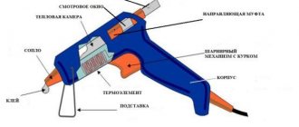
Technology of applying a printed circuit board pattern using a laser printer
When printing on a laser printer, the image formed by the toner is transferred, due to electrostatics, from the photo drum on which the laser beam drew the image, onto paper. The toner is held onto the paper, preserving the image, only due to electrostatics. To fix the toner, the paper is rolled between rollers, one of which is a thermal oven heated to a temperature of 180-220°C. The toner melts and penetrates the paper texture. Once cooled, the toner hardens and adheres firmly to the paper. If the paper is heated again to 180-220°C, the toner will again become liquid. This property of toner is used to transfer images of current-carrying tracks onto a printed circuit board at home.
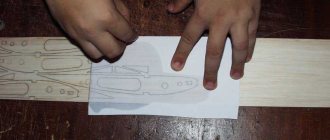
After the file with the printed circuit board design is ready, you need to print it using a laser printer onto paper. Please note that the image of the printed circuit board drawing for this technology must be viewed from the side where the parts are installed!
An inkjet printer is not suitable for these purposes, as it works on a different principle.
Preparing a paper template for transferring the design to the printed circuit board
If you print a printed circuit board design on ordinary paper for office equipment, then due to its porous structure, the toner will penetrate deeply into the body of the paper and when the toner is transferred to the printed circuit board, most of it will remain in the paper. In addition, there will be difficulties in removing paper from the printed circuit board. You will have to soak it in water for a long time. Therefore, to prepare a photomask, you need paper that does not have a porous structure, for example, photo paper, backing from self-adhesive films and labels, tracing paper, pages from glossy magazines.
I use old stock tracing paper as the paper for printing the PCB design. Tracing paper is very thin and it is impossible to print a template directly on it; it gets jammed in the printer. To solve this problem, before printing, you need to apply a drop of any glue to a piece of tracing paper of the required size in the corners and glue it to a sheet of A4 office paper.
This technique allows you to print a printed circuit board design even on the thinnest paper or film. In order for the toner thickness of the drawing to be maximum, before printing, you need to configure the “Printer Properties” by turning off the economical printing mode, and if this function is not available, then select the coarsest type of paper, for example cardboard or something similar. It’s entirely possible that you won’t get a good print the first time, and you’ll have to experiment a little to find the best print mode for your laser printer. In the resulting print of the design, the tracks and contact pads of the printed circuit board must be dense without gaps or smudging, since retouching at this technological stage is useless.
All that remains is to cut the tracing paper along the contour and the template for making the printed circuit board will be ready and you can proceed to the next step, transferring the image onto fiberglass laminate.
Transferring a design from paper to fiberglass
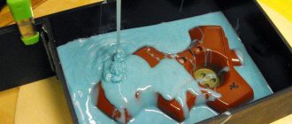
Transferring the printed circuit board design is the most critical step. The essence of the technology is simple: paper, with the side of the printed pattern of the tracks of the printed circuit board, is applied to the copper foil of fiberglass and pressed with great force. Next, this sandwich is heated to a temperature of 180-220°C and then cooled to room temperature. The paper is torn off, and the design remains on the printed circuit board.
Some craftsmen suggest transferring a design from paper to a printed circuit board using an electric iron. I tried this method, but the result was unstable. It is difficult to simultaneously ensure that the toner is heated to the required temperature and that the paper is pressed evenly onto the entire surface of the printed circuit board when the toner hardens. As a result, the pattern is not completely transferred and gaps remain in the pattern of the printed circuit board tracks. Perhaps the iron was not heating up enough, although the regulator was set to maximum iron heating. I didn’t want to open the iron and reconfigure the thermostat. Therefore, I used another technology, less labor-intensive and providing one hundred percent results.
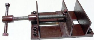
On a piece of foil fiberglass laminate cut to the size of the printed circuit board and degreased with acetone, I glued tracing paper with a pattern printed on it in the corners. On top of the tracing paper I placed, for more even pressure, heels of sheets of office paper. The resulting package was placed on a sheet of plywood and covered on top with a sheet of the same size. This entire sandwich was clamped with maximum force in clamps.
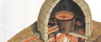
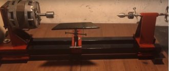
All that remains is to heat the prepared sandwich to a temperature of 200°C and cool. An electric oven with a temperature controller is ideal for heating. It is enough to place the created structure in a cabinet, wait for the set temperature to reach, and after half an hour remove the board to cool.
If you don’t have an electric oven, you can use a gas oven by adjusting the temperature using the gas supply knob using the built-in thermometer. If there is no thermometer or it is faulty, then women can help; the position of the control knob at which pies are baked is suitable.
Since the ends of the plywood were warped, I clamped them with additional clamps just in case. To avoid this phenomenon, it is better to clamp the printed circuit board between metal sheets 5-6 mm thick. You can drill holes in their corners and clamp printed circuit boards, tighten the plates using screws and nuts. M10 will be enough.
After half an hour, the structure has cooled enough for the toner to harden, and the board can be removed. At the first glance at the removed printed circuit board, it becomes clear that the toner transferred from tracing paper to the board perfectly. The tracing paper fit tightly and evenly along the lines of the printed tracks, rings of contact pads and marking letters.
The tracing paper easily came off from almost all the traces of the printed circuit board; the remaining tracing paper was removed with a damp cloth. But still, there were gaps in several places on the printed tracks. This can happen as a result of uneven printing from the printer or remaining dirt or corrosion on the fiberglass foil. Gaps can be painted over with any waterproof paint, manicure polish, or retouched with a marker.
To check the suitability of a marker for retouching a printed circuit board, you need to draw lines on paper with it and moisten the paper with water. If the lines do not blur, then the retouching marker is suitable.
It is best to etch a printed circuit board at home in a solution of ferric chloride or hydrogen peroxide with citric acid. After etching, toner can be easily removed from the printed tracks with a swab soaked in acetone.
Then holes are drilled, conductive paths and contact pads are tinned, and radioelements are sealed.
This is the appearance of the printed circuit board with radio components installed on it. The result is a power supply and switching unit for an electronic system that complements an ordinary toilet with a bidet function.
Corrosion resistance of tin-plated and nickel-plated copper busbar.
The tin coating on the copper current-carrying (grounding) bus is anode (or sacrificial), i.e. The electrochemical potential of tin is more negative than that of copper. This means that in a corrosive environment, tin will be destroyed first and only after the tin has completely dissolved in a certain area will copper be damaged. Tin itself is a fairly corrosion-resistant metal, so the use of a tin coating on a copper busbar significantly increases the service life of such a busbar. An analogy can be drawn with galvanized steel. In a zinc-steel pair, the zinc is also the anode and will corrode first, protecting the steel.
To increase the corrosion resistance of the tin coating on a copper busbar, the coating is deposited from an electrolyte with brightening agents and doped with bismuth (i.e., a tin-bismuth alloy is deposited).
The corrosion resistance of a nickel-plated tire is certainly also high, but it has a drawback. Tin coating (especially shiny) is non-porous starting from a thickness of 6 microns, nickel - from a thickness of 24 microns. with an average required coating thickness of 9-12 microns, tin will have an advantage over nickel. At the same time, a nickel-plated busbar is still better than a busbar without any coating at all.
Materials and tools
The materials are tin and fluxes.
- Tin and alloys. When tinning, tin grade 01 (Sn 99.1%, impurities 0.1%) and grade 02 (Sn 99.5%, impurities 0.5%) are used. Pure tin serves as the basis for a protective coating for dishes. Tin is not used as a solder for soldering, because at low temperatures it becomes brittle. Durability is ensured by adding other components to tin, mainly lead. Tin and lead alloys are used: POS-18, POS-30, POS-50, POS-90. The number in the designation shows the tin content as a percentage.
- Fluxes. They make it easier to clean surfaces from dirt, grease and oxides, and reduce the melting point. The most common fluxes are ammonia (ammonium chloride) and soldering acid (zinc chloride). Often when soldering copper and steel, a mixture of them is used.
The following tools are used:
- measuring instruments (ruler, tape measures, calipers);
- tinning pliers for supporting and moving parts;
- scrapers for scraping contaminants from coated surfaces;
- brushes for applying lubricant and cleaning surfaces;
- blowtorches for heating products before applying poluda.
The choice of technological equipment is determined by the method of tinning and soldering. Auxiliary and main equipment used:
- Baths for galvanic tinning:
- stationary;
- rotating bell baths.
- Tinning machines and installations. These are complex systems consisting of series-connected preparation and tinning baths. They are usually placed in a housing equipped with suction hoods, which improves working conditions.
- Workbenches for tinning and auxiliary work. Preparation of products
The quality of preparation of the surface of a part for tinning determines the strength of its adhesion to the coating. The preparation method depends on the condition of the surface.
- Brushing. This method is used if there is scale or heavy contamination on the surface of the product. It is recommended to wash the product thoroughly before processing. For a better effect, you can use an abrasive substance: sand, lime, pumice.
- Grinding. This is how surfaces that have uneven surfaces are prepared. When sanding, you can use an abrasive wheel or sandpaper.
- Chemical degreasing. It is carried out with special solutions: 5-10% sodium hydroxide solution, 10-15% sodium carbonate solution; 10-15% sodium phosphate solution. They need to be heated to 60-80 degrees. Fat solvents can be used: Vienna lime, gasoline, kerosene. When using gasoline and kerosene, keep in mind that they are explosive and fire hazardous. After removing grease, the products should be washed with water. You can determine whether fat has been removed from the surface or not visually. If water spreads evenly over the surface of the product and does not collect in drops, then the surface is degreased.
After preparation, you can tinning the parts.
Electrical conductivity of tin-coated copper busbar.
Despite the fact that tin-bismuth coating conducts electricity worse than pure copper, it confidently ranks second, except for coating with precious metals. In combination with a number of other undeniable advantages, tin coating on current-carrying busbars is preferable to nickel coating. The fact is that the nickel coating has a strong oxide film on the surface, which explains the high corrosion resistance of nickel. However, this same fact is the reason for the relatively low electrical conductivity of nickel coatings compared to copper and tin.
Preparing the printed circuit board for installation of radio components
The next step is to prepare the printed circuit board for the installation of radio elements. After removing the paint from the board, the tracks need to be sanded in a circular motion with fine sandpaper. There is no need to get carried away, because the copper tracks are thin and can be easily ground off. Just a few passes with abrasive with light pressure are enough.
Next, the current-carrying paths and contact pads of the printed circuit board are coated with alcohol-rosin flux and tinned with soft solder using an electric soldering iron. To prevent the holes on the printed circuit board from being covered with solder, you need to take a little bit of it onto the soldering iron tip.
After completing the manufacture of the printed circuit board, all that remains is to insert the radio components into the designated positions and solder their leads to the pads. Before soldering, the legs of the parts must be moistened with alcohol-rosin flux. If the legs of the radio components are long, then before soldering they need to be cut with side cutters to a protrusion length above the surface of the printed circuit board of 1-1.5 mm. After completing the installation of parts, you need to remove any remaining rosin using any solvent - alcohol, white alcohol or acetone. They all successfully dissolve rosin.
You can learn more about soldering technology using examples of soldering parts, brands of solders and fluxes, design and repair of soldering irons from the series of articles in the section “How to solder with a soldering iron.”
It took no more than five hours to implement this simple capacitive relay circuit from laying out the tracks for manufacturing a printed circuit board to creating a working sample, much less than it took to type up this page.
Wear resistance of tin-plated and nickel-plated copper busbar.
The only serious disadvantage of a tin-plated current-carrying (grounding) busbar over a nickel-plated one is its low wear resistance. However, it is worth noting that the presence of at least some coating always increases the wear resistance of the product, to a greater or lesser extent. The use of wear-resistant coatings is justified only if the bus uses detachable contacts, or if the coating is applied directly to the detachable contact. In this aspect, nickel plating is unrivaled.