Hello, dear readers. I present to your attention an article devoted to motorcycle-type carburetors. Surely many of you have ridden a motorcycle, and some even own one. Maybe you've been to a karting track and competed excitedly on the track, listening to the whistling of tires and the roar of the engine. Or maybe you just arrange your dacha on weekends using gas-powered tools. In these and many other cases, we are dealing with small-displacement internal combustion engines controlled by a carburetor. But what is this detail? What is it for and what does it consist of? What characteristics are affected and how are they regulated? You can find answers to these and a number of other questions in this article.
Let's specify the issues that are considered during the course of the story.
- The first part will discuss the main issues of the formation and ignition of a combustible mixture.
- The second part is devoted to the main metering system, it also describes the methodology for selecting the main fuel jet by analyzing the condition of the spark plug.
- The third part is devoted to the shape and design features of the diffuser and throttle valve.
- The idle system is discussed in the fourth part; in addition, it discusses the operation of the system in transient modes.
- The fifth part discusses a number of carburetor auxiliary devices, describing their purposes, designs and adjustment methods.
- The sixth part is devoted to carburetors with constant vacuum at the nozzle, which are widely used on four-stroke engines.
Today we will consider only the first part.
Due to the large volume of material proposed for study, parts of the article will be formed as separate publications. PS I understand that material of this kind is only indirectly related to the theme of the portal. However, even here in the transport category there are articles devoted to a homemade two-stroke internal combustion engine and even a steam engine. These examples motivated me to publish my work. In addition, publication on such a reputable and well-indexed resource as Habr will help disseminate the material and bring it to an audience interested directly in carburetors. Enjoy and, I hope, useful reading!
Non-ferrous metal alloys
Brass is an alloy of copper and zinc.
The zinc content in brass ranges from 10 to 40%. She. It is well forged, stamped, cast and retains its polish well. Its melting point is 980-1050°. Special brasses may contain, in addition to copper and zinc, manganese, nickel, lead, iron, and aluminum. They have increased strength and good wear resistance. Brass is used in the automotive industry for the manufacture of radiator parts, pipelines, carburetor parts, valves, bushings, etc. For casting carburetor housings and fuel pumps, zinc alloys containing up to 93% zinc are used; These alloys are characterized by low fusibility.
The state standard establishes six grades of copper-zinc alloys.
Table. Copper-zinc alloys
| Alloy | Brand | Chemical composition in% | Application of alloys | |||
| Copper | Lead | Zinc | Other impurities | |||
| Red brass | M-90 | 90 | — | 9,8 | 0,2 | For the manufacture of nipples and other fittings |
| Polutompak | L-80 | 80 | — | 19,75 | 0,25 | For sheets |
| Brass | L-68 | 68 | — | 31,75 | 0,25 | For sleeves, pipes, wires |
| L-62 | 62 | — | 37,6 | 0,4 | for rods, sheets, pipes | |
| L-59 | 59 | — | 40 | 1 | For bars of different profiles | |
| Leaded brass | L-59-1 | 59 | 1,5 | 38,5 | 1 | For threaded products, stamping, various fittings |
Bronze is an alloy of copper and tin. May contain small amounts of nickel, aluminum, silicon, manganese, phosphorus, zinc and lead. In the automotive industry, bronze is used to make all kinds of bushings, bearing shells and other parts. When cast, bronze fills molds well, exhibits low shrinkage, is resistant to oxidation, and can be easily processed with tools. Phosphor bronze, containing up to 0.5% phosphorus, is distinguished by its resistance to acids, wear resistance and good casting properties.
Aluminum bronze consists of 90-97% copper and 10-3% aluminum. It is much stronger than tin bronze and successfully resists chemical influences, can be forged, rolled, pressed, sufficiently fills complex shapes during casting, is elastic and withstands impacts well.
Nickel bronze contains from 3 to 40% nickel and has the highest viscosity, density, strength and hardness. The melting point of bronze is 900-1000°. The grades of bronze used in the automotive industry are given in the table.
Table. Bronze
| Brand | Chemical composition in% | Copper | |||
| Tin | Lead | Zinc | Phosphorus | ||
| Br. OSC 5-10 | 4,5-6 | 8,0-10 | 2 | — | Rest |
| Br. OSC 5-5.5 | 4,5-5,5 | 4,5-5,5 | 4,5-5,5 | — | — |
| Br. OSC 10-2 | 9,0-11,0 | — | 1,0-3,0 | — | — |
| Br. OSC 10-1 | 9,0-11,1 | — | — | 0,4-0,8 | — |
Babbitt is an anti-friction alloy based on tin or lead. The structure of the antifriction alloy consists of a main plastic mass (tin, lead) and interspersed hard grains (antimony). Due to the friction of the shaft on the bearing, the soft (plastic) base of the babbitt wears out faster than the hard components embedded in it. Therefore, the surface of the soft base is slightly lower than the hard particles of the alloy and the shaft with its journals rests on the protruding hard particles of the babbitt bearing. This reduces the friction surface and facilitates oil circulation.
Antifriction alloys made of tin, lead and antimony have the disadvantage that during solidification, the structural components in them are stratified, solid crystals of the chemical compound of antimony with tin crystallize first and, like lighter ones, float to the top, and the main plastic mass remains at the bottom. This phenomenon is called liquation. To eliminate the harmful effects of segregation, copper is introduced into alloys with a tin and tin-lead base, which forms a chemical compound with tin that is more refractory than the above structural components. When the molten alloy is cooled, the chemical compound of copper and tin solidifies first, forming in it a kind of lattice (framework) that prevents the delamination of the structural components. The addition of copper to babbitt also increases its hardness.
Lead bronze is used to fill the liners of compression ignition engines. It is characterized by high strength and refractoriness, but it does not work well on the shaft and can delaminate during pouring (liquation); Therefore, lead bronze bearings require particularly precise adherence to pouring rules and careful preparation. The following antifriction alloys are used for filling bearings and liners of automobile engines.
Table. Babbitts and leaded bronze
| Anti-friction alloy grade | Chemical composition in% | Melting point, C° | |||||||
| Antimony | Copper | Cadmium | Nickel | Arsenic | Tellurium | Tin | Lead | ||
| BN | 13-15 | 1,5-2,0 | 1,25-1,75 | 0,75-1,25 | 0,5-0,9 | — | 9-11 | Rest | 410 |
| BT | 14-16 | 0,7-1,1 | — | — | — | 0,05-0,2 | 9-11 | Rest | — |
| Lead bronze | — | 69-72 | 0,2-0,5 | — | — | — | — | 28-31 | 1080 |
Solders are divided into hard and soft. Hard solders are used where greater mechanical strength is required. In cases where the product is not exposed to heavy loads and high temperatures, soft solders are used. The table shows the composition of soft solders.
Hard solders are used for soldering brass, bronze, copper, etc. PMC-36 brand hard solder contains 36% copper and 64% zinc, PMC-54 solder contains 54% copper and 46% zinc. The first is used for soldering brass, the second is used for soldering copper and bronze.
Hard solders also include silver solders (PSr). For example, for soldering breaker contacts, PSR-12 hard solder is used, consisting of 12% silver, 52% zinc and 36% copper.
Table. Soft solders
| Brand | Chemical composition in% | Note | |||||
| Tin | Antimony | Lead | No more impurities | ||||
| Copper | Bismuth | Arsenic | |||||
| POS-18 | 17-18 | 2-2,5 | Rest | 0,15 | 0,1 | 0,05 | For soldering lead products of automotive parts, for tinning steel before soldering and pouring |
| POS-30 | 29-30 | 1,5-2,0 | — | 0,15 | 0,1 | 0,05 | For soldering radiators and tinning bearings |
| POS-40 | 39-40 | 1,5-2,1 | — | 0,1 | 0,1 | 0,05 | For soldering brass, steel and copper wires |
| POS-50 | 49-51 | 0,8 | — | 0,15 | 0,1 | 0,05 | Same |
Aluminum alloys are used for the manufacture of pistons, cylinder heads, crankcases and other parts. Aluminum alloy has great strength and can be hardened; Some aluminum alloys are close to steel in strength.
In air and water, the aluminum alloy is covered with only a thin light gray film of oxide, and no further oxidation occurs. Alkalis have a destructive effect on this alloy. For hardening, the alloy is placed in a bath with a solution of potash and carbon dioxide, heated to 480-520°, and then cooled in oil. A hardened aluminum alloy can be cut much better than a non-hardened one; Therefore, it is recommended to harden parts made from it before machining.
Aluminum pistons are made from the alloys shown in the table.
Table. Aluminum alloys for pistons
| Car engines | Chemical composition in% | ||||
| Copper | Silicon | Manganese | Iron | Aluminum | |
| Moskvich | 0,3-0,8 | 11,5-13,5 | 0,8-1,5 | up to 0.8 | Rest |
| M-20 Pobeda and GAZ-51 | 6,25-7,75 | 5-6 | 0,25-0,3 | up to 1.5 | — |
| GAZ-MM | 9,75-10,75 | 0,75 | 0,2-0,75 | 0,9-1,5 | — |
| ZIS-5 | 4,5-6,0 | 5,5-7,0 | 0,15-0,35 | 0,8-1,2 | — |
| ZIS-150 | 5,0-7,0 | 5,0-7,0 | 0,15-0,4 | up to 1.5 | — |
Alloys for making pistons are heated to a temperature of 510-520° and quenched in water, and then tempered at a temperature of 165-175° with holding at this temperature for 15-18 hours.
How does a carburetor work?
During the intake stroke, a vacuum forms in the engine intake manifold. Atmospheric air passing through the air filter is sucked into the carburetor. The speed of air movement in the upper and lower parts of the carburetor is noticeably less than in the middle part, where the nozzle is located. The higher the air speed in the diffuser, the more fuel will be drawn out of the tube, and the better the air-fuel mixture (AFM) will be mixed. The fuel jet restricts the fuel flow to keep the BTC mass ratio at 14.7:1. When the engine is running at maximum power, the second chamber of the carburetor is turned on, where the VTS ratio is approximately 13:1. This allows you to enrich the mixture without losing power. Engine power directly depends on the condition of the engine and the composition of the military vehicle. The richer the VTS, the greater the engine power. But it is impossible to increase power indefinitely in this way. Enrichment of the VTS to 14:1 leads to incomplete combustion of fuel, the formation of deposits and coking of rings and valves.
Adjusting the carburetor VAZ 2106
Set of screwdrivers (flat, cross, cross);
- Impact wrench set;
- A set of round bayonets or drills with different diameters;
- rubber bulb;
- toothpicks;
- Flushing mechanism;
- stopping support
- tweezers;
- Mister;
- rag
- Idle speed adjustment is carried out using qualitative and quantitative bolts. The procedure consists of the following steps:
XX adjustment
Start the engine and warm it up to operating temperature of 90˚C, and then turn it off.
- One of the main procedures when setting up a carburetor is adjusting the float chamber. If the gasoline level in the chamber is high, the fuel mixture will be rich, which is not normal. As a result, toxicity and fuel consumption increase. If the level is lower than it should be, there will be insufficient gasoline in various engine operating modes. In this case, set the float tongue so that its jump is 8 mm. It is worth lifting the float, removing the needle and checking whether it is damaged. If the carburetor is flooded, it is better to replace the needle.
Video: how to make idle stable
Adjusting the float chamber
After adjusting the float chamber, check the performance of the auxiliary pump. To do this, remove the carburetor from the engine and remove the top cover from it. Check the pump in the following order:
Adjusting the accelerator pump
Prepare a bottle of clean gasoline, replace the empty carburetor container, and fill the float halfway with fuel.
- When checking the accelerator, pay attention to the direction, shape and quality of the flow. In the case of normal flow, it should be uniform, without deviations or spraying of gasoline. In case of any irregularities, replace the accelerator spray for a new one. Structuring in the carburetor there is an adjusting screw in the form of a conical bolt, the wing of which causes the plug to overflow. With this screw you can change the fuel flow through the support pump, but only to a lesser extent.
The carburetor, as used, must be cleaned and air-bleeded every 10,000 km. Nowadays there are many cleaning tools without removing the unit from the machine. As a rule, however, they only help in cases of minor contamination. With more serious embodiments, it is necessary to remove the device. After removing and disassembling the carburetor, unscrew and clean the filter screen and injectors. Gasoline can be used as a cleaning agent, and if that doesn’t work, as a solvent.
Cleaning or replacing jets
To avoid damaging the diameter of the nozzles, do not use metal objects such as a needle or wire for cleaning. A toothpick or plastic stick of a suitable diameter is best. After cleaning, the nozzles are blown with compressed air to ensure that no dirt remains.
At the end of the entire procedure, we check the compatibility of the injectors with the installed carburetor. Each part is marked with a series of numbers that indicate the performance of the injectors.
Video: how to clean the carburetor
Carburetor markings
Table: numbers and sizes of jets for VAZ 2106 carburetors
| Main system fuel injector | Air nozzle in the main system | Idle injector | Air nozzle for idle speed adjustment | Pressure pump nozzle | 1 stone. | |||||
| 2 cat. | 1 stone | 2 stones | 1 stone | 2 stones. | 1 stone. | 2 stones. | fuel | bypass | 2101-1107010 | |
| 135 | 135 | 170 | 190 | 45 | 60 | 180 | 70 | 40 | 40 | 2101-1107010-02 |
| 130 | 130 | 150 | 190 | 50 | 45 | 170 | 170 | 50 | 40 | 2101-1107010-03; |
| 2101-1107010-30 130 | 130 | 150 | 200 | 45 | 60 | 170 | 70 | 40 | 40 | 2103-1107010 |
| 135 | 140 | 170 | 190 | 50 | 80 | 170 | 70 | 40 | 40 | 2103-1107010-01; |
| 2106-1107010 130 | 140 | 150 | 150 | 45 | 60 | 170 | 70 | 40 | 40 | 2105-1107010-10 |
| 109 | 162 | 170 | 170 | 50 | 60 | 170 | 70 | 40 | 40 | 2105-110711010; |
| 2105-1107010; 2105-1107010-20 107 | 162 | 170 | 170 | 50 | 60 | 170 | 70 | 40 | 40 | 21053 |
| 100 | 115 | 150 | 135 | 35–45 | 50 | 140 | 150 | 45 | 40 | 2107-1107010; |
| 2107-1107010-20 112 | 150 | 150 | 150 | 50 | 60 | 170 | 70 | 40 | 40 | 2107-1107010-10 |
| 125 | 150 | 190 | 150 | 50 | 60 | 170 | 70 | 40 | 40 | 2108-1107010 |
| 97,5 | 97,5 | 165 | 125 | 42 ± 3 | 50 | 170 | 120 | 30/40 | — | The reasons for dismantling an assembly can be different: replacement with a product of a different modification, repair, cleaning. In any case, remove the air filter first. To replace, you will need the following tools: |
Increasing power through changes in the composition of military technical equipment.
By changing the dimensions of the air and fuel jets, you can change the composition of the military technical equipment and engine power within a wide range. True, any change in the composition of the military technical equipment negatively affects the life of the engine. A very lean mixture with a 16:1 BTC ratio burns faster. This leads to fuel detonation. When operating for a long time with a very lean mixture, pistons and valves are destroyed. A highly enriched VTS with a 12:1 ratio increases engine power, but leads to ring sticking and overheating of the cylinder head.
Any carburetor reduces the flow of air into a car engine. The narrower the diffuser, the better the fuel atomization and the higher the quality of the VTS, but the less the amount of VTS entering the cylinders. Carburetors of more powerful engines have a larger diffuser size, so they reduce the filling of the cylinders less. But the quality of military technical support when using them is noticeably worse.
Carburetor from a more powerful car. Installing a carburetor from a more powerful engine will not lead to a significant increase in power. The maximum that can be achieved is an increase in power by 10 percent. With a resource reduction of 10-15 percent. The only way to increase the power of a car is to use a carburetor with the best quality VTS. But such carburetors are much more complex than conventional ones, therefore less reliable, and require special equipment for adjustment.
Single injection. Mono injection is a carburetor, where the fuel supply level is regulated not by the air flow through the diffuser, but by a controller that collects information from a large number of sensors. Mono injection was an attempt to combine a carburetor and an injector, but it could not withstand competition not only with injectors, but also with carburetors.
Installing a carburetor from a larger engine will not significantly increase engine power. If you want your engine to work better, find a good specialist to properly tune the carburetor. Then your motor will increase power and will not lose service life.
Did you like the article? Subscribe to the channel to stay up to date with the most interesting materials
Description of models
The first VAZ 2107 was standardly equipped with a DAAZ carburetor In Russia, they were modified to meet the needs of the local automobile industry. DAAZ products had simple assembly, which subsequently affected their price. The given carburetor model was characterized by maximum simplicity and made it possible to provide good acceleration characteristics to the car. Initially, the space in the engine compartment was created specifically for DAAZ.
The VAZ 2107 carburetor is a complex, high-precision device, consisting of two chambers, one of which - the first is equipped with a special mechanical damper drive. It can be installed on any domestic rear-wheel drive car. The volume of the model in question is 1.5 and 1.6 liters.
Gasoline consumption when using DAAZ increases noticeably. But this is consistent with the car’s speed indicators, which are also increasing. And this is especially important when overtaking.
Drawing our attention to the model - “Ozone” - it is worth noting that this is a more modified version of the standard DAAZ. The new optimized mechanism had better environmental performance. Thanks to this, “Ozone” received its environmentally friendly name. In addition, it consumed much less fuel than the previous version, so for such an economical car as the VAZ 2107, the Ozone carburetor was considered the most optimal option of all possible.
Good maneuverability and speed of the car were given by a pneumatic valve located in the new carburetor and ensuring the efficiency of the second chamber. However, there was one “but” - even if the valve was slightly dirty, the second chamber stopped working. The speed of the vehicle immediately decreased. This was noticeable in the acceleration dynamics of the car and when the engine was running at medium speeds.
The Solex 21053 carburetor is no less popular among VAZ 2107 owners. At the moment, it is the latest development. Solex has a rather complex assembly, but at the same time it has a fuel reverse supply system, which makes this carburetor the most economical among the entire DAAZ line.
The carburetor mechanism has a larger volume compared to other models: 1.8 Solex versus 1.5, 1.6 other DAAZs. All these features tell us that this carburetor model is simultaneously designed for economical and fast driving.
Initially, Solex was created for cars with front-wheel drive. And yet, this carburetor can be installed on a VAZ 2107 without special modifications. Solex is picky only about the quality of fuel.
Important! The system may malfunction! In most cases, this is due to the fact that the air and fuel channels are clogged with dust. The solution to this issue will be timely maintenance of the carburetor.
All of the carburetors we list are installed on classic engines. If the size of your engine is not designed for the existing carburetor, then you will need to select and replace the jets. It is also worth adjusting the carburetor.
On the issue of non-standard carburetors, it is worth saying that in some cases, owners of “classics” resort to just such a solution. Without alterations and adjustments there is no question here.
“Solex” 21073 is a model designed for engines with a volume of 1.7 liters. The carburetor differs from previous versions by large channels and jets. Dynamic growth is guaranteed! But so does the subsequent expense.
The following non-standard model is installed on cars of the VAZ 2108 and 2109 series. “Solex” 21083 for installation on version 2107 will require certain modifications. Also, installing it will lead to the fact that at about 4000 rpm the engine will not be able to spin up any further. To install this carburetor model, you need to drill out the chamber diffusers. Then expand them. During the modification process, large jets are also installed. The result of such work can please you: fuel consumption will be lower, and the dynamics will exceed those of other models.
Car carburetor
Car carburetors have one, two or four mixing chambers. Multi-chamber carburetors are available with simultaneous or sequential opening of the throttle valves. [1]
The diameters of the jets of automobile carburetors are small (0 6 - f - 4 - 2 5 mm), so it is difficult to determine the speed and compression coefficients of the jet separately for such small holes. [3]
To eliminate the influence of the air cleaner on the quality of the mixture, in most modern car carburetors the float chamber is sealed and communicates through a channel with the cavity of the intake pipe. [4]
An example of functional interchangeability is the method for determining tolerances on the dimensions of calibrated channels of carburetor jets, developed by prof. [5]
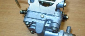
Motorcycle engines have a number of features that make their carburetors significantly different from automobile carburetors. [6]
Alloys of zinc with copper, aluminum and magnesium are usually used for the manufacture of parts operating under friction conditions. Zinc alloys are used for the manufacture of parts for automobile carburetors, gasoline pumps, windshield wipers, and electrical devices. [7]
The same principle is used in more advanced pumps considered in molecular physics. A spray gun (Fig. 10.13) and a car carburetor work on the same principle. But in them the gas stream carries away the liquid, the latter breaking into small droplets. [8]
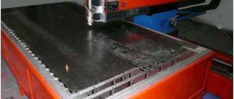
For example, the total cost of molybdenum alloy rods used in aluminum die casting machines after 60,000 to 80,000 castings is approximately 6 times less than that of steel rods. TZM alloy rods, after receiving more than 100,000 aluminum alloy carburetor body castings, retain their original shape and satisfactory surface finish. [9]
When fuel consumption fluctuates at an operating pressure of 100 cm and a temperature of 20 C by an amount AQ 0 05 cm / sec, the tolerance for the nozzle diameter d 0 88 mm should be equal to 5 μm. It was found from an equation relating fluid flow to the geometric and operational parameters of automobile carburetor jets. [10]
It should be noted that at low loads there is no need to supply water, and it is not supplied due to the absence of a pressure difference in the float chamber and channel 18, which exits into the carburetor suction pipe. At idle, the engine is fed through a system of idle jet channels, not much different from those found on automobile carburetors. [eleven]
The carburetor body 7 is a casting made of zinc or aluminum alloy with two large holes, the axes of which are mutually perpendicular. The lower position of the spool determines the minimum stable engine speed at idle and is adjusted with a special screw. Some carburetors sometimes have an additional spool 2, which performs the same functions as the air damper in a car carburetor. An adjusting needle 11 is connected to the throttle valve, the end of which, having a strictly defined profile, enters the hole in the nozzle 10 of the main jet. [12]
The lowest measurable flow rate is 0.05 kg/h, or 0.014 g/s. The dynamic properties of the bridge are high. Its time constant is 5 - 15 ms. It was successfully used to study the operation of a car carburetor. [14]
The most important issues of the subject classification methodology are: the use of broad and narrow headings, inversion in their wording, and the use of subheadings. The subject heading should define the specific content of documents as accurately as possible. So, for example, if it deals with automobile carburetors, then the heading should be formulated as Carburetors, and not as Internal Combustion Engines or Automobiles. The use of broad categories is only justified in cases where the relevant broad content is involved, for example when the document refers to internal combustion engines or cars in general. [15]
Zinc carburetors - Chemist's Handbook 21
Zinc is anodic to most commonly used metals and should theoretically protect them on contact.
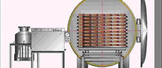
Some practice data confirm this, but the ratio of the anode and cathode surfaces should be taken into account. For example, carburetors (zinc die casting) equipped with brass liners practically do not corrode even in the presence of water, since in this case the cathode surface is much smaller than the anode surface. If the opposite phenomenon occurs in the design, i.e., a small zinc part comes into contact with a large surface of an electropositive (more noble) metal, corrosion of the zinc is inevitable. [p.307] The solubility of corrosion products in gasoline depends on the molecular weight of the acid. As it increases, the solubility of salts in gasoline improves. Insoluble corrosion products are deposited on the walls of the container or are suspended. In the latter case, coming along with gasoline, they can clog filters or carburetor jets and thereby cause interruptions in engine operation [231. Corrosion products deposited on the metal in the form of a film protect it from further corrosion and in this regard play a positive role. Thus, after removing corrosion products, a zinc plate placed in gasoline lost 1.5 times more weight in 48 hours than in 1.5 months of storage [24]. [p.294] Casting zinc, lead, tin. The scale of casting products from these metals is usually small. Printing fonts are cast from alloys of tin, lead and antimony, and parts of automobile engines (carburetor housings, pumps, filters) are cast from zinc alloys. For casting, melting crucibles with electric or indirect gas heating are mainly used. Sometimes in cities located in the area of the main gas pipeline, instead of electric heating or heating with liquid fuel, heating with gas fuel is used, which allows more precise control of the temperature regime and facilitates the start-up and shutdown of the furnace. [p.316] Tests in an aqueous layer of a mixture of gasoline with water (operating conditions of a carburetor or gas tank) showed for rolled zinc with a chromate film a weight loss of only 0.0027 g, and for rolled zinc without a film with the same sample sizes and equal conditions - 0.2691 g. For many years, chromate films have been successfully used to protect against corrosion of floats for carburetors cast from a zinc alloy under pressure, as well as gas tanks, which are usually hot-dip galvanized. [p.930]
Increasing the oxygen concentration in water increases the corrosion rate of zinc Stable. 2). At high oxygen levels, corrosion usually occurs evenly. However, when the oxygen concentration drops below a certain limit and the water becomes unevenly saturated, galvanic couples are formed between the oxygen-rich and oxygen-poor areas, causing the zinc to be subjected to pitting, the corrosion rate increasing, and bulky corrosion products being formed. In practice, typical cases of such corrosion can be observed on carburetors made of zinc alloys in places where water stagnates under gasoline or on stacked zinc or galvanized steel sheets when moisture gets into the spaces between them. [p.302]
chem21.info
What to make a gasket for a carburetor from
Many car enthusiasts are faced with the need to replace gaskets, of which there are many in the car and which, for one reason or another, become unusable. The carburetor is the most important element that supplies the engine with fuel in the required quantity, which ensures smooth operation of the engine, and due to a leaky gasket, the fuel supply is disrupted.
The engine begins to malfunction, sneeze, or even stall completely. The fuel supply system must be very tight. If the tightness is broken, a lot of excess air is sucked into the mixture, which disrupts the quality of the engine. And the carburetor gasket is a common cause of unsatisfactory tightness, which requires its replacement.
You can do the repairs yourself, but what to make a carburetor gasket from at home and in what sequence will be described below.
Necessary materials
Here's what you can use to make a carburetor gasket:
- Paronitis.
- Gasoline resistant rubber.
- Metal asbestos.
- Cardboard.
Here is a basic list of materials suitable for making gaskets.
Unfortunately, these materials are not always at hand for the car enthusiast, but cardboard is available to everyone and in large quantities. It should be dense and have a thickness of about 0.8-1 mm. This is the most common material among car enthusiasts who have decided to acquire the skills of an auto mechanic. And it’s not always possible to complete the required work the first time, the work is quite delicate, you can ruin more than one workpiece, wasting expensive and scarce materials in vain, but cardboard is always at hand and the quality of the gaskets made from it is very good.
Stages of work
First, remove the carburetor. We disassemble it and remove the old gasket. During all work, extreme care must be taken to avoid harming the parts inside the carburetor and to prevent the ingress of dust and various debris. Contact surfaces must be thoroughly cleaned. To cut out a new gasket, it is not recommended to use the old gasket as a template. There will be inaccuracies. Now let's analyze alternative materials.
Cardboard gasket
Cardboard gasket
To cut the gasket exactly along the contour, the desired place should be coated with a thin layer, for example, grease, ink, etc. Then we apply a cardboard sheet to the carburetor so that not the slightest displacement of both parts occurs. Now it's done, all that's left to do is cut it out. The most convenient way to cut out a part is with nail scissors; finding them is also not a problem. You can punch the required holes using a specially selected tube, the edges of which are sharpened so as not to tear the part being manufactured. Place the workpiece on any wooden object with a flat surface, place the tube in the right place and hit it with a hammer as sharply as possible. It doesn’t hurt to lubricate the finished gasket with sealant, but only a little, otherwise the excess sealant will squeeze out into the float chamber after assembly.
It is necessary to take into account the thickness of the new part and if it is thicker than the original, you should adjust the position of the float and reconfigure the carburetor at idle. There is nothing complicated about replacing the gasket yourself, and there is no financial investment either. Special attention was paid to the cardboard, now briefly from what you can cut out the gasket for the carburetor.
Paronite gasket
Paronite gasket
Paronite is a good option, but gasoline causes it to peel off, crumble inside and clog the carburetor channels. Of course, there is also petrol-resistant paronite, but it is not always and not available everywhere.
Metal asbestos gasket
Gasket for carburetor made of metal asbestos
If it is high-density, the result is a very high-quality gasket. But it is also quite scarce, like gasoline-resistant tires.
And finally, some useful tips:
- Fuel consumption and engine power directly depend on correctly installed carburetor gaskets. If problems arise in operation, it is necessary to urgently replace the gaskets.
- You can make gaskets with your own hands from almost any material. From PCB as well. You just need special scissors to cut it.
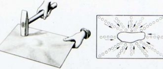
- It is easier to cut any contour from rubber, but more difficult with holes. Therefore, in order for the holes to turn out as required, the workpiece is tightly clamped between the boards and drilled with a drill with a drill bit of the required diameter.
- Thermal insulating gasket can be prepared from thin textolite and placed 2-3 of them to the required thickness. This will not negatively affect the thermal insulation.
- And if you buy a new gasket in a store, you must first make sure that this is exactly what you need.
By paying due attention to your car, you can always avoid costly and time-consuming repairs. And with ingenuity and hard work, you can do a lot with your own hands.
Lada 2108 GL On style › Logbook › A little bit of my theory about installing 4 carburetors
A little theory and pictures!) I’ll tell you and show you in pictures (you never know, I’ll be old and gray-haired, but some young man will want to stick a 4-carb into his lifebar. And then bam, he sat down... And he’ll end up on my page and understand everything what’s what) , since I have encountered, I won’t say a lot, but not a few, with some important nuances, and not only me! It seems like putting 4 carbs on a car is like two fingers, but there is actually very little information on the Internet! Of course, thanks to the guys of Drive who helped in any way they could, this is LukasKh (this is generally my main Mechanic of my perverted ideas), mOdO, Tero42 (I apologize that I can’t send links to their pages, since I’m on my phone) but I think it’s not difficult to find them in the vastness of Drive, if anything, I think they will help. And so to the point! What do you need? (I’m telling you about my carburetors). - preferably 4 carburetors from a motorcycle - a stock manifold from a VAZ 2108, we only need the part that is screwed to the cylinder head, the rest is cut off and thrown away (you can, of course, immediately order a ready-made flange from a turner). — 4 conical tubes with a diameter, one end of the inner part is 24 mm, the other is 34 mm, but since we have argon workers (mom, make a snowball!) I settled on a 24 mm pipe. We cut these tubes on one side (you can see in the photo how much to get a radius of 30 Approximately). We weld these tubes to the flanges from a standard manifold. We do this whole thing by approximation! I grabbed it, looked at it, and put it out! I don’t know what exact dimensions of the collector, everything was done along the way. — a 30cm pipe with a diameter of 42mm (so that it is not afraid of gasoline and is more fire resistant). Mode for 4 parts (the pipes serve only to connect two parts). — 8 strong clamps (to connect the carbs with pipes to the manifold) — The sealant is fire-resistant, you can lubricate the joints. — Oh, I also cut off two pipes from the standard manifold, the ones that go to VUT and the economizer, and welded them onto the 1st-4th tube (on the 1st for the economizer, on the 4th under the VUT). - return! (Required!) I often saw questions about how to make a return? And I didn’t understand it myself, because motorcycle carbs don’t have it. You need a tee for supplying fuel from the fuel pump to the carbs, two fittings on the tee, those that go from the pump to the carbs, let them have an internal diameter of 8mm, for example, and the return fitting should be narrower (less!) 5mm. And if the carb fittings are for two fuel inlets , then of course you need to install two tees. (Well, I think it doesn’t take much intelligence to power it where). - Jets. Feel free to use TJ from Ozone. (Zhigulevsky carb).
— and so on according to the system itself of 4 Keihin carburetors (on other carbs it may be a little different, although I doubt it).
tube 1 - ventilation of the lower chamber of the vacuum damper, must be open, on motorbikes it is connected to the air box with a filter tube 2 - ventilation of the float chambers, must also be open + take it away from the exhaust manifold, because if it overflows, gasoline will flow out of it . 3 and 4 are the same. 5 draining the sludge from the float chamber, you also need to set the level in the float chambers by connecting a transparent tube and unscrewing the screw, you can see the level inside the chamber 6 supplying gasoline from the return tee, return is required! Otherwise, fuel will be forced through the floats 7, heating the intake manifold, you don’t have to connect it at all. 9 idle speed control, the screw that slightly opens the throttle valve 10 is also heated, it passes through a draft. 11 screw for adjusting the mixture composition, usually unscrewed by 2.25-2.5 turns 12 and 8 look like vacuum fittings, they are needed to synchronize the dampers, and then they can be connected to the distributor vacuum, theoretically there should be such fittings on each carb, look carefully to see if they are broken off somewhere 13 enrichment bar, something like a suction on the carbs, you move it, start it, wait a couple of minutes, let it go. In short, he wrote that he was able to smoke everyone on the sly
What material are carburetors made of?
There are three main materials from which carburetors are made: cast iron, zinc and aluminum. Beginning in the 1930s, cast iron began to be replaced by zinc, and in the late 1950s, aluminum replaced much (but not all) zinc. In most cases, cast iron finishes with black oxide,
although it is sometimes painted black. Carter recommended a special black carburetor paint when rebuilding the carburetor. So while carbs like W-1 Carter were originally treated with black oxide, many are now - correctly - semi-gloss black. Rochester Carbon also used cast iron in the throttle body section. This part has always been black oxide and no paint recommendations have been made. The most famous carburetor material is olive green zinc. Zinc itself is a bright, silvery metal that reacts with air and water to produce a powdery white material often called “white rust.” To prevent this, carburetor parts are treated at the factory with a chromic acid solution, which forms a thin layer of "zinc chromatin" on the surface of the metal. This is very effective at protecting the metal from water or air damage. This is why carburetors are usually green!
Hello, can you please tell me what metal the body of the mechanical fuel pump is made of?
Some carburetors were made from zinc, breaking off a piece of that old unnecessary carburetor and throwing it into hydrochloric acid, we in the USSR obtained soldering acid and soldered radiators perfectly.
Subscribe
to our channel in
Index.Zen
Even more useful tips in a convenient format
Car carburetor
Car carburetors have one, two or four mixing chambers. Multi-chamber carburetors are available with simultaneous or sequential opening of the throttle valves. [1]
The diameters of the jets of automobile carburetors are small (0 6 - f - 4 - 2 5 mm), so it is difficult to determine the speed and compression coefficients of the jet separately for such small holes. [3]
To eliminate the influence of the air cleaner on the quality of the mixture, in most modern car carburetors the float chamber is sealed and communicates through a channel with the cavity of the intake pipe. [4]
An example of functional interchangeability is the method for determining tolerances on the dimensions of calibrated channels of carburetor jets, developed by prof. [5]
Motorcycle engines have a number of features that make their carburetors significantly different from automobile carburetors. [6]
Alloys of zinc with copper, aluminum and magnesium are usually used for the manufacture of parts operating under friction conditions. Zinc alloys are used for the manufacture of parts for automobile carburetors, gasoline pumps, windshield wipers, and electrical devices. [7]
The same principle is used in more advanced pumps considered in molecular physics. A spray gun (Fig. 10.13) and a car carburetor work on the same principle. But in them the gas stream carries away the liquid, the latter breaking into small droplets. [8]
For example, the total cost of molybdenum alloy rods used in aluminum die casting machines after 60,000 to 80,000 castings is approximately 6 times less than that of steel rods. TZM alloy rods, after receiving more than 100,000 aluminum alloy carburetor body castings, retain their original shape and satisfactory surface finish. [9]
When fuel consumption fluctuates at an operating pressure of 100 cm and a temperature of 20 C by an amount AQ 0 05 cm / sec, the tolerance for the nozzle diameter d 0 88 mm should be equal to 5 μm. It was found from an equation relating fluid flow to the geometric and operational parameters of automobile carburetor jets. [10]
It should be noted that at low loads there is no need to supply water, and it is not supplied due to the absence of a pressure difference in the float chamber and channel 18, which exits into the carburetor suction pipe. At idle, the engine is fed through a system of idle jet channels, not much different from those found on automobile carburetors. [eleven]
The carburetor body 7 is a casting made of zinc or aluminum alloy with two large holes, the axes of which are mutually perpendicular. The lower position of the spool determines the minimum stable engine speed at idle and is adjusted with a special screw. Some carburetors sometimes have an additional spool 2, which performs the same functions as the air damper in a car carburetor. An adjusting needle 11 is connected to the throttle valve, the end of which, having a strictly defined profile, enters the hole in the nozzle 10 of the main jet. [12]
Two-chamber carburetor body with centrally located piston accelerator pump
The utility model relates to mechanical engineering, in particular to carburetor housings of internal combustion engines manufactured by injection molding. The utility model makes it possible to reduce defects in the casting of housings and ensure more stable engine operation during lateral rolls of the vehicle. The body of a two-chamber carburetor with a central location of the cavity of the piston accelerator pump, located between two vertical cavities of the main air paths, has a sector in the central part of the partition separating the float chamber from the cavities of the main air paths. The arc of the sector protrudes inside the float chamber and is formed by connecting the outer side walls of the holes in the emulsion wells, the hole for the accelerator pump drive guide, the hole for installing the economizer valve and placing the economizer rod guide. The distance L1 between the centers of the emulsion wells is in the range of 0.7LL1L, where L is the distance between the centers of the cavities of the main air paths. When using a carburetor body in accordance with the utility model, when casting bodies made in accordance with this utility model, it was possible to reduce internal manufacturing defects in the manufacture of carburetor bodies of type K126-K135 by 15%. At the same time, the consumer qualities of cars with carburetors of the K126-K135 type were improved by increasing the stability of the engine when the car was tilted sideways. (1 n.p.f., 2 z.p.f., 3 fig.).
The utility model relates to mechanical engineering, in particular to carburetor housings of internal combustion engines manufactured by injection molding.
The carburetor body is a product of complex shape, having walls and partitions of significantly different thicknesses. Carburetor bodies are made from various alloys of non-ferrous metals, for example TsAM4-1 based on zinc or AK12M2 based on aluminum. When making carburetor bodies by injection molding, the rate of crystallization of thin and massive parts of the castings is different, therefore they have different crystal structures, which in turn leads to the formation of gas-air and shrinkage porosity, the formation of cavities, leading to loss of tightness of the carburetor body.
The body of the float chamber of a two-chamber carburetor is known (Carburetors K-126, K-135, GAZ, PAZ. Operating principle, design, adjustment, repair. Tikhomirov A.N., "WHEEL", Moscow, 64, 2002), made by the method injection molding, having two vertical cavities of the main air paths, with an adjacent common float chamber separated from them by a partition.
The layout solution of the carburetor body involves placing an accelerator pump in the carburetor partition, including the working cavity of the pump, holes for the accelerator pump drive guide, holes for installing the economizer valve and placing the economizer rod guide. In addition, in the partition separating the cavities of the main air paths from the float chamber, there are holes for two emulsion wells. With this arrangement, a massive thick partition is formed in the carburetor body, the individual parts of which have significantly different thicknesses, creating a thermal unit in the center of the partition, which can lead to the formation of pores and cavities in the partition, loss of tightness and an increase in defects when casting carburetor bodies. During the operation of carburetors of these models, problems were identified in the functioning of the main metering systems when they are located closer to the edges of the float chamber, associated with a disruption in the fuel supply during lateral rolls of the car, causing malfunctions in the engine.
The problem solved by the proposed utility model is to create a housing for two-chamber carburetors with a central location of a piston accelerator pump that is devoid of the above disadvantages, namely, reducing defects in casting housings and ensuring continuous operation of the engine with large lateral rolls of the car.
This technical result is achieved by the fact that the body of the two-chamber carburetor is made with a central location of the cavity of the piston accelerator pump, located between two vertical cavities of the main air paths, and a float chamber of a predominantly rectangular shape adjacent to them on the side of the accelerator pump. In the partition separating the cavities of the main air paths from the float chamber there are holes for two emulsion wells, a hole for the accelerator pump drive guide, a hole communicating with the float chamber, intended for installing the economizer valve and placing the economizer rod guide. In accordance with the utility model, in the central part of the partition separating the float chamber from the cavities of the main air paths, there is a sector, the arc of which protrudes inside the float chamber and is formed by connecting the outer side walls of the holes of the emulsion wells, the hole for the accelerator pump drive guide, and the hole intended for installing the valve economizer and placement of the economizer rod guide. The distance L1 between the centers of the emulsion wells is in the range:
0.7LL1L, where
L is the distance between the centers of the cavities of the main air ducts;
L1 is the distance between the centers of the emulsion wells. It is preferable to make a longitudinal rectangular cut in the side wall of the hole protruding into the inside of the float chamber, intended for installing the economizer valve and placing the economizer rod guide, to ensure that fuel enters from the float chamber into the economizer valve hole. This cutout shape is easy to cast and further reduces the thickness of the partition.
In addition, the partition separating the float chamber from the cavities of the main air paths may have at least one hole adjacent to the sector and associated with the side wall of the hole in the emulsion well. This design solution makes it possible to install additional systems in the carburetor, for example an econostat channel, without changing the carburetor layout or significantly increasing the thickness of the partition, which affects the yield of usable casings.
Thanks to the uniform distribution of the holes in the emulsion wells, the hole for the accelerator pump drive guide and the hole for installing the economizer valve with a guide surface for its drive in the sector around the working cavity of the accelerator pump, the difference between the thicknesses of the individual parts of the partition is reduced, which ensures a more uniform distribution of the alloy mass throughout volume of the partition sector and reduces the likelihood of the formation of pores and cavities.
The shape of the sector arc, in the form of connecting the walls of the above holes protruding into the inside of the float chamber, will reduce the mass of the partition sector protruding into the inside of the float chamber. In addition, due to the use of a sector, the mass of tides in the corners of the float chamber, where the partition is interfaced with the body, is reduced.
The distance L1 between the centers of the emulsion wells, selected in accordance with the above range, ensures optimal performance of the task. The location of the centers of the emulsion wells at distances L1 smaller than the distance L between the centers of the cavities of the main air ducts makes it possible to reduce the length of the sector arc and, accordingly, the sector area, the mass and thickness of the partition in the center of the carburetor, which makes it possible to significantly reduce the size of the thermal unit and reduce the percentage of defects from the formation pores and shells. The distance L 1 between the centers of the emulsion wells cannot be less than the value indicated in the range, since in this case the thickness of the walls of the holes forming the sector arc, in places where they interface with each other, will become so small that this will lead to an increase in rejects and a decrease in output suitable hulls due to the formation of non-sheets and sink marks.
Placing the holes of the emulsion wells in the sector of the body partition, closer to the center of the carburetor body, ensures more stable engine operation at large lateral inclinations of the vehicle, since with this arrangement the relative magnitude of the change in the fuel level in the emulsion well is reduced, depending on the angle of lateral inclination of the engine, with a carburetor installed on it, the N axis of which is oriented in the direction of movement of the car, which leads to the cessation of fuel flow into the engine.
Figure 1 shows a top view of the carburetor body of type K 135.
In Fig.2. shows an axonometric view of section A-A of the carburetor body of type 135.
Figure 3 shows a top view of the K126 type carburetor body with auxiliary holes.
Example 1 shows the design of the K135 carburetor body (Fig. 1). The housing 1 of the float chamber of a two-chamber carburetor has a cavity 2 for housing the piston (not shown) of the accelerator pump, located in the center of the housing 1 on the axis of symmetry N, between the cavities of the 3 main air paths (see Fig. 1). Housing 1 has a float chamber 4 of a predominantly rectangular shape, separated by a partition 5 from the cavities of the 3 main air paths. On the side of the float chamber 4 around the cavity of the accelerator pump 2 there are holes for two emulsion wells 6, a hole 7 for a guide (not shown) for the accelerator pump drive, a hole 8 intended for installing the economizer valve (not shown) and placing the economizer drive rod guide. The partition 5 has a sector “C” into which holes 6, 7, 8 are interlocked with the center lying on the axis of the housing N, the arc of which protrudes inside the float chamber 4. Hole 8 for installing the economizer valve and placing the economizer rod guide has a longitudinal rectangular cutout in the side surface with the help of which fuel flows from the float chamber to the economizer valve (Fig. 2). The centers of the emulsion wells 6 are located at the ends of the arc of sector “C”, symmetrically relative to the axis of the body N. The distance L1 between the centers of the emulsion wells 6 is less than the distance L between the centers of the main air paths 3 by 17%.
Example 2 shows the design of the carburetor body type K-126 (Fig. 3). The body 1 of the float chamber of a two-chamber carburetor is made as described above in example 1. In the partition 5 there is a hole 9 for the econostat channel and a hole 10, which is a reserve one.
The carburetor body manufactured in accordance with this utility model is intended for use in K126N, K126G, K126I, K126M K135, K135MU, K135G carburetors, intended for preparing a high-quality air-fuel mixture for internal combustion engines of cars and trucks. Placing the emulsion wells closer to the center of the carburetor makes it possible to meet the requirements for engine performance when the vehicle rolls sideways.
The manufacture of a two-chamber carburetor body involves feeding molten metal into a mold under excess pressure in the following sequence: molten metal is poured into the press cup, the pressing mechanism is turned on, and the piston displaces the metal into the mold cavity. After pouring the metal into the mold, it is kept for a set time, after which the mold opens and the finished casting of the carburetor body is pushed out of it. To increase the density of the casting and reduce gas-air porosity, a technological process mode is additionally used in which static pressure is transferred to the metal from the moment of final filling of the mold until complete solidification. Under conditions of rapid solidification, an important condition for pre-pressing is the creation of such thermal conditions under which the metal simultaneously hardens in all parts of the mold, which depends on the difference in the thickness of the walls and partitions in different parts of the body. The design of the carburetor body in accordance with the claimed utility model makes it possible to reduce this difference, ensuring the creation of a sealed casting with a fine-grained structure and high mechanical properties.
Thus, when casting bodies made in accordance with this utility model, it was possible to reduce internal manufacturing defects in the manufacture of carburetor bodies of type K126-K135 by 15%. At the same time, the consumer qualities of cars with carburetors of the K126-K135 type were improved, by increasing the stability of the engine when the car was tilted sideways.
1. The body of a two-chamber carburetor with a central location of the cavity of the piston accelerator pump, located between two vertical cavities of the main air paths and a float chamber adjacent to them from the side of the accelerator pump, which is predominantly rectangular in shape, while in the partition separating the cavities of the main air paths from the float chamber, there are holes for two emulsion wells, a hole for the accelerator pump drive guide, a hole communicating with the float chamber, intended for installing the economizer valve and placing the economizer rod guide, characterized in that in the central part of the partition separating the float chamber from the cavities of the main air paths, there is a sector , the arc of which protrudes inside the float chamber and is formed by connecting the outer side walls of the holes of the emulsion wells, the hole for the accelerator pump drive guide, the hole intended for installing the economizer valve and placing the economizer rod guide, and the distance L1 between the centers of the emulsion wells is in the range:
0.7LL1L,
where L is the distance between the centers of the cavities of the main air paths;
L1 is the distance between the centers of the emulsion wells.
2. The carburetor body with a central location of the cavity of the piston accelerator pump according to claim 1, characterized in that the side wall of the hole protruding into the inside of the float chamber, intended for installing the economizer valve and placing the economizer rod guide, has a longitudinal rectangular cutout.
3. A carburetor body with a central location of the cavity of the piston accelerator pump according to claim 1, characterized in that in the partition separating the float chamber from the cavities of the main air paths, there is at least one hole adjacent to the sector and associated with the side wall of the hole emulsion well.
poleznayamodel.ru
Carburetor - What is it? Operating principle, problems, carburetor repair
Carburetors mix fuel and air and also control the volume of the air-fuel mixture that enters the engine.
In this article we will describe the basics of the functioning of the carburetor system.
Engines do not actually draw fuel from the carburetor. All carburetors are equipped with a diffuser, which narrows the air throat of the carburetor. When air passes through this narrowing, a pressure drop (rarefaction) is formed there. At this place there is a small hole, which is installed there for the purpose of supplying fuel. Atmospheric pressure acting on the fuel literally squeezes it out of the carburetor's float chamber through this hole, heading towards the carburetor neck. From there, the fuel enters the intake manifold, and then into the engine cylinders. The engine requires a fuel-air mixture of different compositions in different operating modes.
Main parts of the carburetor
The carburetor system includes the following main parts:
- The float chamber is the cavity in the carburetor that maintains the optimal fuel level. This process occurs through a mechanism consisting of a float and a clearance needle;
- Diffuser. At this point, the carburetor air channel narrows and the air flow speed increases;
- The mixing chamber is the main air path, which includes a number of fuel metering systems, diffusers and a throttle valve;
- Jet. In the carburetor it functions as a dispenser. Externally similar to a threaded plug with a calibrated hole. The purpose of the jet is to accurately dose fuel (fuel jet), air (air) or emulsion (emulsion) in carburetor systems;
- Idle system. It is a device that prepares a combustible mixture at idle speed under light loads;
- The main dosing system is a complex of elements, which includes jets, channels, sprayers and emulsion tubes. All this prepares the mixture at medium and large loads;
- Economizer. This is a device that enriches the mixture when it reaches full load in order to achieve maximum power;
- Econostat is an additional dosing system. As a rule, it is used to enrich the mixture at maximum crankshaft speeds when the load is full;
- The accelerator pump is a plunger or diaphragm pump that supplies an additional dose of fuel to the mixing chamber when the throttle valve is suddenly opened. The accelerator pump prevents the engine from “failing” during operation;
- Adjustment screws. Their function is to change the air to fuel ratio at idle.
Last breath: how and why they installed electronic control on carburetors
Why did the injector change the carburetor?
Many people believe that in the evolution of power systems for automobile gasoline engines, carburetors were successively replaced by single injection, then distributed injection, and then direct. However, not everyone knows that there was a short period of development of carburetor engines when they managed to come close in terms of characteristics to injection engines! This happened thanks to MPSZ - microprocessor ignition systems. The imperfections of the classic power supply and ignition system have been no secret to auto engineers since the appearance of the first cars. The carburetor principle of mixture formation and the centrifugal-vacuum principle of maintaining an optimal ignition angle have always been considered a compromise - the engine has too many transient modes in which the carburetor and distributor are not able to ensure optimal engine operation, combining maximum efficiency, throttle response, elasticity, power and the complete absence of detonation. But the ECU, the electronic computing unit that controls the fuel injectors and spark plugs of the injection system, can.
However, all the antediluvian mechanical and electromechanical injection systems that existed before the era of the advent of full-fledged electronically controlled distributed injectors (from the “komandogeret” of Luftwaffe aircraft engines to numerous generations of automobile “jetronics”), in fact, differed little for the better from high-quality carburetors. And it came to the practical implementation of the injector in its most widespread modern form only when the level of development of electronics allowed it. It was simply unrealistic to create a full-fledged ECU unit for an injector using radio tubes in the 50s of the twentieth century. Making it with transistors from the 60s is the same. Only in the 80s, thanks to the spread of compact microcircuits and powerful transistors, the ECU acquired the functionality, dimensions and appearance familiar to us today.
The carburetor goes away, but does not give up
Once upon a time, the first carburetors were a primitive tube with a single jet and a throttle valve. However, over decades of evolution, their design has become incredibly complex. They never became ideal devices for preparing an air-fuel mixture, but they came noticeably closer to them. Therefore, despite the fact that the transition to distributed electronically controlled injection was a foregone conclusion and obvious even to the engineers of Soviet automobile factories, the thought that millions of carburetor cars had not yet exhausted their potential haunted many.
Articles / Compact van Treatment with fire: how Soviet car enthusiasts repaired tires Amazing devices were found in the trunks of Soviet drivers! Give some of them to a modern car owner, and not everyone will even understand what they are and how to use them. “Wheels” are trying... 12375 3 9 08/31/2018
The fact is that it is not for nothing that a modern carburetor has a complex design: thanks to this, being in good working order and perfectly adjusted, it copes quite well with the task of preparing the correct fuel-air mixture in various engine operating modes and taking into account a variety of external conditions. This means that you can try to leave the carburetor alone and turn your attention to the second of the two most important conditions for engine operation - proper ignition. The distributor with its poor vacuum and centrifugal advance angle regulators is a bottleneck in the engine; it largely destroys everything that the carburetor provides. Therefore, you can try to supplement the carburetor with a smart electronic ignition system, and it will approach the efficiency of an injector. This is how microprocessor ignition systems were born.
To understand the ideology of these systems, one important point should be noted. Many remember how almost every Soviet owner of a VAZ classic, Moskvich or Volga sought to replace the unstable and primitive standard contact ignition with a contactless electronic one. In the latter, the contact group was removed from the distributor and replaced with a Hall sensor, an inductive sensor, or even an infrared sensor. So, electronic contactless ignition systems and MPSZ are completely different things.
Electronic non-contact ignition only made it possible to get rid of the contact pair and reduce the dependence of the spark power on the voltage drop in the on-board network by the starter. Well, sometimes it took on the function of a manual octane corrector. And MPSZ not only did everything the same, but also - what is much more important - automatically adjusted the ignition timing parameters based on the crankshaft position, speed and intake pressure. With the development of microprocessor systems, it has become possible, if desired, to add a knock sensor, lambda probe, antifreeze and intake air temperature sensors. Moreover, this adjustment was continuous, almost like an injector. The controller quickly responded to changes in engine operating conditions and adjusted the ignition timing, taking into account, among other things, the quality of the fuel.
All owners of carburetor cars with installed microprocessor ignition, ranging from fairly old and primitive MPSZ models to modern ones, with the ability to independently manually correct OZ graphs via Bluetooth from a smartphone (!), noted radical changes in the behavior of the car. The “carb” engine really “woke up”, running perfectly smooth at idle and becoming responsive and very elastic in motion. Also, MPSZ minimized the difference between gasoline and gas if gas equipment was installed on the car.
Auto enthusiast industry
The first domestic injectors appeared on VAZs in the mid-90s, but became widespread only in the early 2000s. Automobile factories of the USSR, and then Russia, were stuck at the “carburetor stage” for too long. The last carburetor cars rolled off the assembly lines of VAZ and UAZ already in 2006, before the introduction of the Euro-2 environmental standard in our country, into which the “carb” no longer fit. The massive and irreversible transition to injection systems was greatly delayed, and therefore the intermediate stage with the use of MPSZ for car factories turned out to be unacceptable.
Under the hood of Lada 111 '1997–2009
However, Soviet industry in the late 80s produced factory sets of MPSZ controllers with peripherals and wiring. The models bore names typical of their time, such as “Electronics-MS2713-02” or “Electronics-MS4004”. They were produced here in Moscow and “almost here”, in Sofia, Bulgaria. Such factory-produced MPSZ controllers were equipped with a full set of components for self-installation of the system on a car, including distributed ignition coils (which were often paired coils from Oka) and even a plug installed in place of the distributor being removed.
The main sensor was, of course, the crankshaft position sensor, which had to be installed in the gearbox opposite the flywheel teeth. The second most important was the vacuum sensor in the intake manifold, which served as the main source of information about the engine load for smart electronics. For MPSZ “Electronics” systems, this sensor was built directly into the controller body itself and was connected to a fitting in the carburetor with a thin hose.
However, despite the high level of gadgets under the Electronics brand, the system never became widespread. In the 80s, the Volzhsky Automobile Plant produced a small number of front-wheel drive cars with MPSZ "Electronics" for export; They were extremely rare in general sale as kits for self-installation, and few people knew about them. And with the collapse of the USSR in 1991, factory-made MPSZs completely disappeared from store shelves.
For about ten years there was a complete lull in the field of microprocessor ignition, but around the beginning of the 2000s this niche was occupied by small-scale amateur home-made workers and tuning enthusiasts, who are completely “embracing” it to this day, creating quite complex and very smart devices. True, the number of such projects was relatively small and is now gradually decreasing, because these days the demand for MPSZ is gradually falling due to the retirement of carburetor engines and cars with them...
Injector as a donor for the carburetor
By the way, it is worth mentioning an interesting branch of the development of MPSZ systems, which they received already in the injection era. Many enthusiasts of carburetor cars in the mid-2000s almost simultaneously came to the idea lying on the surface. Since control units for injection engines such as “Januaries”, “Mikasov” and other “Boschs” have become cheaper, it has become possible to purchase them for very little money at disassembly sites. But the injection ECU is an almost ready-made and very perfect unit for a carburetor MPSZ.
The fact is that the injection ECU, in fact, does not know where it works. On your own injection engine, on a carburetor engine, or even on a laboratory table or on your knee. The unit simply methodically carries out its program - it receives information from sensors and, based on this data, issues control signals for injection and ignition. And if you connect a carburetor to the ECU instead of fuel injectors, attach an ignition module and sensors to it, then the electronic unit will work and flawlessly supply a spark at the right moment with an accuracy inaccessible to even the best distributor, controlling speed, engine load, temperature and detonation. To do this, however, you need to correct the firmware by writing its stripped-down “carburetor” version. But for real enthusiasts it's not that difficult.
Receiving information from the crankshaft position sensor, intake pressure, detonation, and sometimes even from lambda probes (if the owner of a carburetor car was not too lazy to embed them in the muffler), popular and widespread ECUs of the “January” type gave many old cars a second wind.
However, let us repeat: today the story with the MPSZ is gradually fading away. Microprocessor ignition would be damn relevant in the form of a factory system on cars of the “pre-injection” era, but domestic car factories were unable to cope with this intermediate innovation. Nowadays, there are fewer and fewer carburetor cars, and many of those who are ready to do something serious with their own hands with their favorite, but middle-aged car, prefer to assemble a complete injection and ignition kit, which, using used components from disassembly, sometimes turns out to be comparable in price with MPSZ kit for carburetor...
The principle of operation of the carburetor
Carburetors are divided into types, and each type operates in its own individual way. For example, wicks function by forcing air currents to leak across the surface of gas-impregnated wicks. As a result of this process, gasoline vapors evaporate into the atmosphere. But, it is worth recognizing that we are talking about wick carburetors in order to cover a complete overview of information about carburetors. In fact, this method has long ceased to be used, since it became obsolete more than a hundred years ago.
Basically, today's carburetors function thanks to a spray mechanism. They work by using the Venturi effect to draw gasoline out of the chamber.
All carburetors that operate according to the Bernoulli principle have some special features. The change in air pressure is predictable and directly proportional to the speed of its movement. This is significant because the air passing through the carburetor contains a narrow, compressed venturi. Its function is to accelerate the air flow passing through it.
The air functions only thanks to pedal . It and the throttle valve, which is located in the carburetor, are connected to each other by a cable. This valve closes the tube when the accelerator pedal is not used, and when this pedal is pressed, it opens it. This allows air to pass through the venturi.
It turns out that more fuel is being sucked in from the mixing chamber. It is these principles that underlie the operation of the carburetor.
The vast majority of these devices are equipped with an additional valve above the Venturi tube (throttle). It is partially closed when the engine is not running, which in turn makes the amount of air that can pass into the carburetor less. This creates a richer mixture/air or fuel, so the throttle will open when the engine starts and warm up, because it will no longer need a rich mixture to operate.
Other components of the carburetor system are also designed to affect the air-fuel mixture under different operating conditions.
The carburetor is a complex element, and all its technical work is also quite complex.
Problems in the carburetor system
There are a number of problems in carburetors that can be solved by adjusting the mixture air damper or cold speed, while others require repair or replacement. The carburetor membrane often wears out. This manifests itself in the fact that it stops pumping fuel into the chambers.
When the carburetor fails, the engine may not function well when exposed to certain conditions.
There are also problems with the carburetor, due to which the engine can break down - it stops working correctly at idle, and at this moment outside help becomes necessary.
Frequent difficulties in the carburetor system arise in winter, when the engine is very difficult to start on its own. An engine that works hard in cold weather functions well in warm weather.
Many problems with the carburetor system can be resolved by manually adjusting the mixture or idle speed. To do this, the mixture is adjusted by turning one or the other screw.
Development and production
In the history of the automotive industry, the caburator was designed and assembled in 1895 by a self-taught technician of German origin, Wilhelm Maybach. Carburetor engines, like the carburetors themselves, have changed more than once over the years, but the principle of their operation has remained unchanged. The technology of fuel evaporation, used in the first versions of carburetors to form a fuel-air mixture, in modern models has been replaced by fuel atomization technology, which has become the main difference and advantage of this vehicle unit.
Carburetors of a new design began to be mass produced in 1925 by the world famous Bosch concern. The reliability and safety of vehicles was improved by making changes to the design of carburetors related to the integration of the fuel pump and fuel injection system. Design changes to the carburetor made it possible to begin creating innovative power units running on diesel fuel. Ten years later, the first car equipped with a diesel engine rolled off the assembly line of the Mercedes plant.
The established production of injection engines began to require an increase in the power of gasoline engines. This was achieved through the introduction of an intake manifold, which provoked the start of production in the mid-40s of engines with a direct fuel injection system and a higher-power carburetor.
In 1965, the Bosch concern released a new version of the carburetor with a distributed fuel injection system onto the automotive market. The design of the carburetor was significantly changed and acquired an electric pump, which replaced the fuel injection pump, which resulted in a reduction in the cost and dimensions of the entire unit.
The first carburetor with a multipoint fuel injection system was released by Bosch
In 1994, Mitsubishi Motors introduced a direct fuel injection system into carburetor engines. This design solution had its advantages: fuel economy coupled with achieving maximum torque.
Carburetor repair
If you make changes or perform some corrections without removing the device from the engine, you can solve many problems. However, some problems can only be solved by removing the device and various parts. The carburetor can be restored. This operation usually involves removing the block, then disassembling it into parts and cleaning it using a solvent that is designed specifically for this purpose.
Many of the carburetor's "guts", seals and other parts must then be replaced before the installation process. Only after careful processing has occurred, you need to assemble all the parts into the carburetor and install it.
For quality service, it is recommended to have a repair kit for the carburetor system. It should include everything you need.
On the information site for car enthusiasts "FORAM" you can find a lot of useful information regarding car repair and maintenance.