- home
- Directory
- Physics
When exposed to external forces, bodies are capable of acquiring acceleration or deformation.
Deformation is a change in the size and (or) shape of a body. If, after removing the external load, the body restores its size and shape completely, then such deformation is called elastic. Let the spring in Fig. 1 be acted upon by a tensile force directed vertically downward.
When exposed to a deforming force ($\overline{F}$), the length of the spring increases. An elastic force (${\overline{F}}_u$) arises in the spring, which balances the deforming force. If the deformation is small and elastic, then the elongation of the spring ($\Delta l$) is proportional to the deforming force:
\[\overline{F}=k\Delta l\left(1\right),\]
where the proportionality coefficient is the spring stiffness $k$. The coefficient $k$ is also called the elasticity coefficient, the stiffness coefficient. Stiffness (as a property) characterizes the elastic properties of a body subjected to deformation - this is the body’s ability to resist external force and maintain its geometric parameters. The stiffness coefficient is the main characteristic of stiffness.
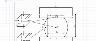
The spring stiffness coefficient depends on the material from which the spring is made and its geometric characteristics. Thus, the stiffness coefficient of a twisted cylindrical spring, which is wound from round wire, subjected to elastic deformation along its axis, is calculated using the formula:
\[k=\frac{Gd^4}{8d^3_pn}\left(2\right),\]
where $G$ is the shear modulus (a value depending on the material); $d$ is the wire diameter; $d_p$ is the diameter of the spring coil; $n$ — number of spring turns.
What is the stiffness coefficient of the rod if it is subjected to a force of 1000?
Answer: rod stiffness
is k = 1 * 10^6 N/m.
Interesting materials:
Can I use foil for baking in a slow cooker? Can I use regular cookware on an induction cooker? Can I use a regular frying pan on an induction hob? Can silicone baking pans be used in a gas oven? Can I use an induction pan on a gas stove? Can a non-stick frying pan be used in the oven? Can metal drills be used on wood? Can microwave cookware be used in the oven? Can a stone frying pan be used in the oven? Can induction pans be used on gas?
Specific hardness indicators
0
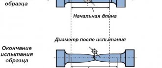
When comparing the stiffness, strength and weight of parts made from different materials, four main cases should be distinguished.
1. The parts are identical in configuration (under equal load they have the same stresses).
2. The parts are equally rigid (have the same deformations at different sections and stresses).
3. The parts are of equal strength (have the same safety margin, different sections and stresses proportional to the tensile strength of the material).
4. The parts have the same mass.
The first case (replacing the material of a part with another without changing its geometric dimensions) practically occurs when the sections of the part are specified by the technological process (for example, cast body parts). This is also the case of non-design parts with uncertain stresses. The second and third cases occur when replacing the material of a part with another while simultaneously changing its sections (calculated parts in which stresses and deformations are determined quite accurately and are assigned with the calculation of maximum use of the strength and rigidity of the material). The fourth case is the case when the mass of the structure is determined by its functional purpose and operating conditions.
When comparing the strength, mass and rigidity parameters of parts made of different materials, we will assume that the length of the parts is the same, and the sections in the last three cases change geometrically in a similar way.
1. Parts of the same configuration (σ = const). In the case of tension-compression, the relative stiffness coefficient according to the formula () λ' = EF, where F is the section of the part; E—modulus of normal elasticity.
By condition F = const. Consequently, λ = const E, i.e. the rigidity of the parts in this case depends only on the elastic modulus.
Factor of safety n = σв/σ, where σв is the tensile strength; σ is the stress acting in the part.
By condition σ = const. Consequently, n = const σв.
Part mass m = γFI = const γ, where γ is the density of the material.
The relationships in the case of bending and torsion are completely similar, with the only difference being that in torsion the rigidity of the part is determined by the shear modulus.
2. Equally rigid parts (λ = const). Condition of equal rigidity in the case of tension-compression according to formula ()
Hence,
Mass of equally rigid parts
Voltages
Taking into account formula (52) σ = const E. Safety factor
When bending, the mass of equally rigid parts
Margin of safety
3. Equal-strength parts (n = const). Condition of equal strength in tension-compression
Due to the fact that σ = const/F, n = const σвF = const. Therefore, for parts of equal strength
and mass
Stiffness coefficient taking into account formula (53)
When bending
4. Parts of equal mass (m = const). Condition of equal mass under tension-compression m = γFl = const.
Therefore, F = 1/γ.
Voltages
Margin of safety
Hardness coefficient
When bending
For comparative purposes, the simplest formulas for tension and compression are used.
Indicators of mass, stiffness and tensile-compressive strength for all the cases discussed above are given in table. 19.
The values of specific strength n/m = σ0.2/γ and specific rigidity λ/m = E/γ are the same for all categories of parts.
As can be seen from table. , the value of E/γ is the same for most materials (E/γ ≈ 25·106). The exceptions are gray cast iron (E/γ = 11·106) and high-strength cast iron (E/γ = 21·106).
Taking into account the data in table. 19 and graphs of indicators of rigidity, strength and mass of parts made of various materials were compiled (Fig. 93).
In the case of parts of the same configuration (Fig. 93, a), steels and Ti alloys are most advantageous in terms of rigidity E and strength σ0.2, and Al and Mg alloys are most advantageous in terms of mass γ.
Since the modulus of elasticity of alloys is determined by the modulus of elasticity of the main component and depends little on the content (in usual quantities) of alloying elements (for example, for steels the fluctuations are within the range E = (19-22) 104 MPa, for Al alloys within the range E =( 7.0—7.5) 104 MPa), then in the case of parts of the same configuration, when rigidity requirements are in the foreground and the stress level is low, it is advisable to use the cheapest materials (carbon steels instead of alloyed ones, aluminum alloys of simple composition instead of alloyed ones ). If, along with rigidity, strength is important, then strong alloys are preferred.
For parts of equal rigidity (Fig. 93, b) in terms of strength (σ0.2/E), super-strong steels and Ti alloys are most advantageous. The mass of equally rigid parts is the same (with the exception of parts made of gray cast iron).
In the case of equal-strength parts (Fig. 93, c), super-strong and alloy steels, SVAM and Ti alloys have the smallest mass and the lowest rigidity. The most rigid parts are made of carbon steels, cast alloys of Al and Mg and gray cast iron, i.e. the least durable materials.
This is only true under the condition of equal strength (calculated stresses are proportional to the ultimate strength). The rigidity of parts made of durable materials can be increased by reducing the design stresses, but at the expense of the weight of the structure and with underutilization of their strength resource. The practical conclusion is that when using durable materials in structures of equal strength, it is necessary to take into account a decrease in rigidity and compensate for its decrease with structural measures.
In the case of parts of equal mass (Fig. 93, d), the strength is proportional to the factor σ0.2/γ. The rigidity is the same (with the exception of parts made of gray cast iron, which have reduced rigidity).
Let's compare the rigidity, strength and weight of parts made of carbon, alloy steels and alloys of Al, Mg and Ti (Table 20). The characteristics of parts made of carbon steels are assumed to be equal to unity.
For parts of the same configuration, the transition from carbon steel to cast alloys Al and Mg causes a decrease in rigidity, strength and weight. When switching to gray cast iron, the rigidity decreases by 2.5 and the strength by 2 times. The mass remains virtually unchanged.
For parts of equal rigidity, the transition from carbon steel to wrought Al alloys, alloy steels and Ti alloys is accompanied by an increase in strength by 2.5, respectively; 3,3 and 5 times. The mass of parts does not change.
For parts of equal strength, the transition to Al alloys, alloy steels and Ti alloys causes a decrease in rigidity and weight, respectively, by 2.5; 3 and 5 times.
For parts of equal mass, the transition to Al alloys, alloy steels and Ti alloys is accompanied by an increase in strength by 2.5, respectively; 3 and 5 times. The hardness does not change.
Generalized indicator . As can be seen from table. 19, strength for all categories of parts is determined by the factor σ0.2/γ, and rigidity by the factor E/γ.
The generalized indicator, which is the product σ0.2E/γ2 of these factors, characterizes the ability of materials to bear the highest loads with the least deformation and weight and most fully assesses the profitability of materials by weight.
Strength and rigidity are practically inseparable. Stiffness in itself is of no value if the structure cannot bear high loads. Low carbon steel has the same modulus of elasticity as heat-treated quality steel. However, the carbon steel part is plastically deformed and will fail under the influence of small loads, which will cause only minor elastic deformations in the second part.
The profitability of materials with E/γ = const ≈ 25·106 (see table) is fully characterized by the factor σ0.2/γ, which in this case is a universal strength-stiffness indicator. For materials with a different value of E/γ, the factor σ0.2/γ must be corrected by the ratio of their specific stiffness to E/γ = 25·106, for example, for cast iron; gray - by 11/25 = 0.44, high-strength - by 21/25 = 0.85.
The values of the generalized indicator σ0.2E/γ2 are given in table. and in Fig. 94.
In practice, the choice of material is determined not only by strength and stiffness characteristics, but also by other properties (technological). Therefore, design measures that make it possible to create sufficiently strong and rigid structures even when using materials of low strength and rigidity are of primary importance.
Spring stretch
Let's take a closer look at tensile deformation using the example of a spring.
Let's attach a spring to some surface (Fig. 2). The figure on the left shows the initial length \(L_{0}\) of the spring.
Rice. 2. By comparing the length of the free spring with the length of the loaded one, you can find its elongation
Now let's hang a weight on the spring. The spring will have the length \(L\) shown in the figure to the right.
Let's compare the length of the loaded spring with the length of the freely hanging spring.
\[ \large L_{0} + \Delta L = L \]
Let's find the difference (difference) between the lengths of a freely hanging spring and a spring with a load. To do this, subtract the value \(L_{0}\) from both sides of this equation.
\[ \large \boxed{ \Delta L = L — L_{0} }\]
\( L_{0} \left(\text{m} \right) \) – initial length of the spring;
\( L \left(\text{m} \right) \) – final length of the stretched spring;
\( \Delta L \left(\text{m} \right) \) – a piece of length by which the spring was stretched;
The quantity \(\Delta L\) is called the elongation of the spring.
Sometimes relative elongation is calculated. This elongation is often expressed as a decimal fraction. Or a fraction whose denominator is the number 100 - such a fraction is called a percentage.
Note: A ratio is a fraction. Relative means fractional.
\[ \large \boxed{ \frac{\Delta L }{ L_{0}} = \frac{ L — L_{0}}{L_{0} } = \varepsilon } \]
\( \varepsilon \) is the ratio (proportion) of the stretch of the spring to its initial length. It is measured as a percentage and is called relative elongation.
Shore hardness measurement
Shor's name was Albert. He was an American industrialist who lived in the 20th century. I developed a hardness scale in order to make my work easier and make the enterprise successful.
The plant produced low-modulus materials. They are characterized by low longitudinal elasticity. This results in high elasticity, even at room temperatures. These are polymers, vulcanization products, rubbers, and some plastics. It is for them that the Shor method was created.
Shore hardness of materials is an empirical method. This means that he is experienced, aimed at studying facts, observation.
The indicator turns out to be “disconnected”. There is no connection with the fundamental characteristics of the test sample. But its hardness affects its performance parameters. So, the Shore hardness of rubber is of interest, for example, to motorists.
They rely on the scale when buying tires. Their hardness standard is from 50 to 75 Shore units. The softer the rubber, the better its grip on the road.
However, the pliability of the material leads to its rapid wear and heating. Soft rubber is noisy and quickly loses its shape. The Shore number allows you to select the ideal tires for specific conditions and needs.
Only now, only about 30% of manufacturers indicate the scale indicator on their tires. The presence of a note indicates a responsible approach to business and the quality of the product. problem in determining Shore hardness . There would be a desire. The apparatus for the experiments is simple, as is the scheme for conducting them.
The only negative is a decent spread of results. But a more convenient method has not yet been invented. Let's move from theory to practice?
Shore hardness. Shore method and scale
The ability to resist penetration into the surface layers of another body. This is the definition of hardness. But how can this definition be determined and recorded in what numbers? Hundreds of scientists have worked on this. About 10 of them created universal hardness scales.
They are aimed at different materials and differ in the nuances of measurements. One of these scales is Shore hardness . Who he was, and how he approached the issue of the resistance of some materials to others, we will tell further.
conclusions
- Elastic bodies are those that resist deformation;
- During deformation, a force arises in elastic bodies, it prevents deformation, it is called the elastic force;
- Deformation is a change in the shape or size of the body;
- There are several types of deformation: bending, torsion, shear, tension/compression;
- The elongation of a spring is the difference between its final and initial lengths;
- A compressed or stretched spring has potential energy (in general, any elastically deformed body has potential energy);
- A system consisting of several identical springs will have a stiffness coefficient different from that of a single spring;
- If the springs are connected in parallel, the stiffness coefficient of the system increases;
- And if you connect the springs in series, the stiffness coefficient of the system will decrease.
We connect two identical springs
In physics problem books and textbooks for preparing for the Unified State Exam, there are problems in which identical springs are connected in series or in parallel.
Parallel connection of springs
Figure 5a shows a freely hanging spring. Let's load it (Fig. 5b), it will stretch by the amount \(\Delta L\). Let's connect two such springs in parallel and hang a load in the middle of the crossbar (Fig. 5c). The figure shows that a structure of two parallel springs under the action of a load will stretch less than a single such spring.
Rice. 5. Two springs connected in parallel are deformed less than one such spring
Let us compare the stretch of two identical springs connected in parallel with the stretch of one spring. We hang one load weighing \(mg\) from the springs.
One spring:
\[ \large k_{1} \cdot \Delta L = m \cdot g \]
Two parallel springs:
\[ \large k_{\text{parallel}} \cdot \Delta L \cdot \frac{1}{2}= m \cdot g \]
Since the right sides of the equations are the same, the left sides will also be equal:
\[ \large k_{\text{parallel}} \cdot \Delta L \cdot \frac{1}{2}= k_{1} \cdot \Delta L \]
Both sides of the equation contain the value \(\Delta L\). Let's divide both sides of the equation by it:
\[ \large k_{\text{parallel}} \cdot \frac{1}{2}= k_{1} \]
Let's multiply both sides of the resulting equation by the number 2:
\[ \large \boxed{ k_{\text{parallel}} = 2k_{1} } \]
The stiffness coefficient \(k_{\text{parallel}}\) of two springs connected in parallel has doubled compared to one such spring
Series connection of springs
Figure 6a illustrates a free-hanging spring. The loaded spring (Fig. 6b) is stretched to a length \(\Delta L\). Now let's take two such springs and connect them in series. Let's hang a load on these (Fig. 6c) springs.
Practice shows that a structure of two springs connected in series under the action of a load will stretch more than a single spring.
Each spring in the chain is subject to the weight of the load. Under the influence of weight, the spring stretches and transmits this weight further along the chain without changes. He stretches the next spring. And that, in turn, is stretched by the same amount \(\Delta L\).
Note: Under the influence of force, the spring stretches and transmits this tensile force further along the chain without changes
Rice. 6. A system consisting of two identical springs connected in series, more than one spring is deformed
Let's compare the stretch of two identical springs connected in series and the stretch of a single spring. In both cases, we suspend the same load weighing \(mg\) from the springs.
One spring:
\[ \large k_{1} \cdot \Delta L = m \cdot g \]
Two springs in series:
\[ \large k_{\text{last}} \cdot \Delta L \cdot 2 = m \cdot g \]
Since the right sides of the equations are the same, the left sides will also be equal:
\[ \large k_{\text{last}} \cdot \Delta L \cdot 2 = k_{1} \cdot \Delta L \]
Both sides of the equation contain the value \(\Delta L\). Let's divide both sides of the equation by it:
\[ \large k_{\text{last}} \cdot 2 = k_{1} \]
Divide both sides of the resulting equation by the number 2:
\[ \large \boxed{ k_{\text{last}} = \frac{k_{1}}{2} } \]
The stiffness coefficient \(k_{\text{last}}\) of two springs connected in series will be halved compared to one such spring
Application of Shore measurement
Shore hardness is a table that can indicate the nuances of using products. So, if the eraser indicator is 20 units, then it is artistic. Creators need soft erasers that do not damage drawing paper and can delicately shade, for example, pencil sketches.
For office purposes, schools, or offices, erasers with a hardness of about 50 Shore units are better suited. When buying sealant for construction or housework, it is important to know whether it will be easy to open. For example, we fixed some seams in the bathroom.
If the sealant darkens or cracks, it will have to be scraped out. This is more difficult than cleaning regular grout. The softer and more pliable the sealant, the easier it will be, so to speak, to dismantle it.
The sealant should have a Shore hardness of 10-25 units. Otherwise, the product is not of high quality.
For bicycle tubes, acceptable Shore hardness units are much lower than for car tires. For a bike, 30 points is enough.
Skateboard wheels are cut. Even mild variations should have 75 units. For hard skateboard wheels, the figure is completely equal to the recommendations for solid forklift tires - 95-98 units.
For comparison, plastic construction helmets for protection during work guarantee only 75 points. Purchasing low-quality headgear with a Shore hardness of 40-60 can cost your life.
Shore measurement principle
Shore had to develop the hardness device himself. This happened in 1920. The device is called a durometer. It has a support platform with a hole in the center, an indenter, that is, a presser, and a calibrated spring that applies a certain force to it.
The last element of the machine is the indicator. It determines the degree to which the indenter “nose” extends beyond the supporting surface.
The device has several measuring scales. There are two main ones, A and D. The breakdown is necessary for the accuracy of the experiments, because the subjects are materials with different hardnesses. Soft ones are checked on scale A, and more elastic ones - on D.
Measuring Shore hardness requires attention to external conditions. Some polymers react, for example, to air humidity, or soften under the influence of direct sunlight. It is necessary to exclude factors that influence the parameters of the material. There are ISO standards for this.
Requirements also apply to the thickness of the test sample. It should not be less than 6 millimeters. The width of the material should allow for an indentation from any of the edges of at least 12 millimeters. The smoothness of the subject is also important.
Rough materials may not adhere tightly to the supporting surface, which will distort the measurement results.
To determine, for example, the Shore hardness of polyurethane , the durometer is installed vertically. The “nose” of the indenter, in this case, must be 12 millimeters from the edge of the sample.
You need to press the supporting surface to the sample as quickly as possible, without pushing, keeping the parallel between the planes. All that remains is to apply pressure to the supporting surface to ensure reliable contact with the material being tested. For this purpose, a load is used. But, manual bench press is also allowed.