Welding is an important stage in the creation of new objects and their elements. The performance characteristics of the connections depend on the correctness of the process. Welded structures are created in several ways, using different materials and apparatus. The choice of technology depends on the required characteristics of the seams.
Welding is an important stage in the creation of new objects and their elements.
Total information
Metal structures are used everywhere: industrial and civil buildings, production facilities and equipment, parts of transport routes, etc. There are different ways to connect metal structures, they are distinguished:
- Rivet connections;
- bolted connections;
- welded joints;
Welding is becoming a common solution when choosing a method for connecting metal elements, since a welded structure has a number of advantages:
- Relative ease of manufacture;
- High speed of work;
- Large selection of materials and equipment for welding;
- Ability to create structures of complex configuration;
- Creation of an equally strong hermetic connection;
- Connection of metal meshes and reinforcement cages.
Let's talk in more detail about welded metal structures.
Classification
Classification of welded metal structures is divided into:
According to the materials of the workpieces from which they are made:
- Pipe
- Leafy
- Profile
- Rod
According to the material from which the structure is made:
Metal:
- Made of black steel;
- Made from low, medium and high alloy steel;
- From non-ferrous metals;
- From alloys;
Non-metallic:
- Polyethylene;
- Polypropylene;
- Composite;
According to the type of industrial facility on which they are mounted:
- Oil;
- Gas;
- Thermal power;
- Nuclear power structures;
- Ship;
- Aviation;
- lifting structures.
Types of welded metal structures
Metal structures are something without which it is very difficult to imagine the most modern construction industry. Along with reinforced concrete, they are the most common solution for industrial, public and civil buildings and structures, mechanical engineering and other industries. The most common types (groups) of building metal welded structures are steel:
- Columns.
- Beams.
- Connections
- Shells.
- Cases.
- Rod.
- Lattice.
- Farms.
- Welded supports (for pipelines or equipment).
- Leafy.
Let's talk in more detail about some welded structures, their features during manufacturing and installation. Their production is carried out at enterprises that manufacture metal structures and directly at the construction and repair site.
Metal welded trusses
Welded steel trusses are a flat lattice system of metal elements that allows you to span large spans of buildings and structures.
A truss is a structural element of a building that serves to support the roofing system (purlins, decking, roofing pie) and transfer the load from it to columns or walls.
Metal trusses are often used in the construction of industrial buildings, since the technological process often does not allow the installation of intermediate racks.
Also, steel trusses are most widely used in the construction of social and administrative buildings. Such as: shopping centers, cinemas, stadiums, swimming pools and many others.
It is such buildings that are characterized by the presence of large free internal space. The metal welded truss consists of:
- Knots of the upper belt.
- Raskosov.
- Stoeck.
Braces, in turn, are divided into supporting and ordinary. Support braces are located at the point where the truss is supported. They carry heavy loads, so their cross-section is often larger than that of ordinary braces (or the grade of steel is higher).
Farms can be homogeneous or combined. Because they can combine elements made from different grades of steel.
It is combined metal structures that are an effective solution; their use is most rational in cases where the loads on the elements are significantly different. The braces, as well as the truss posts, are connected to the lower as well as the upper chord directly or using gussets. Their elements can be made from:
- Square pipe.
- Rectangular pipe.
- Round pipe.
- Corner.
- Various profiles.
Steel trusses are the most common solution. Trusses are developed for a specific construction project or selected according to a series, having performed the appropriate calculations.
Truss drawings are developed in the KM and KMD section, where basic instructions for the production and installation of structures are also prescribed.
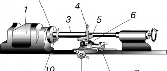
CLASSIFICATION OF WELDED STRUCTURES. AND FEATURES OF SEPARATE TYPES. § 1. Principles of classification
The exceptional diversity of welded structures makes it difficult to classify them uniformly. They can be classified according to the method of obtaining blanks (sheet, cast-welded, forged-welded, stamp-welded structures), by intended purpose (carriage, ship, aircraft, etc.), depending on the thickness of the welded elements (thin-walled and thick-walled) or by the materials used ( steel, aluminum, titanium, etc.). When considering issues of design and manufacture of welded structures, it is more appropriate to classify them depending on the characteristic features of their work. In this case, the following types of welded elements and structures can be distinguished and appropriate definitions given to them.
Beams are structural elements that work primarily in transverse bending. Beams rigidly connected to each other form frame structures.
Columns are elements that work primarily in compression or compression with longitudinal bending.
Lattice structures are a system of rods connected at nodes in such a way that the rods experience mainly tension or compression. These include trusses, masts, reinforcement meshes and frames.
Shell structures, as a rule, experience excess pressure - they are required to have tight connections. This type includes various containers, vessels and pipelines.
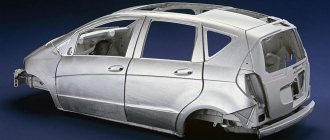
Hull transport structures are subject to dynamic loads. They are subject to high rigidity requirements with minimal weight. The main structures of this type are the hulls of ships, carriages, and car bodies.
Parts of machines and devices operate primarily under variable, repetitive loads. Characteristic of them is the requirement for precise dimensions, which is ensured mainly by mechanical processing of blanks or finished parts. Examples of such products are frames, shafts, wheels.
In accordance with this classification, we will consider the design features of each type in more detail.
The types of cross sections and sizes of welded beams are very diverse. If the load is applied in a vertical plane, I-beams are most often used. When applying loads in the vertical and horizontal planes, as well as under the action of torque, it is more appropriate to use box-section beams.
Typically, a welded I-beam consists of three main sheet elements: a wall and two flanges (belts), but can have vertical and horizontal stiffeners (Fig. 12.1). For large I-beam sizes, its wall (Fig. 12.2a) and chords
(Fig. 12.2.6) can be composite. Such beams have found application in the construction of road bridge spans. The stability of the vertical wall is ensured by vertical and horizontal stiffeners; the cross-section changes due to changes in the width and thickness of the belts.
The launch in 1978 of the country's first wide-flange I-beam rolling shop expands the possibilities for rational design of welded beams - Fig. 12.3. Composite sub-cracking and lattice structures. Ti-
new beams from use - ___ *
We use wide-flange I-beams - new designs of crane bars with a thin wall and belts
of the brands obtained by dissolving wide-flange I-beams are shown in Fig. 12.3. Welded beams with a span of 6 m and a height of 800-1300 mm are supposed to be manufactured with widened upper chords for cranes with a lifting capacity of 10-20 tons without stiffeners and for cranes of 30-50 tons with stiffeners. Beams with a span of 12 m and a height of 1100-1600 mm are provided with chords of the same width and with stiffeners.
| Rice. 12.4. Examples of columns of constant (a) and variable (b, c) sections: a. b - solid; in - through |
Box beams are widely used in overhead crane designs. Typically, transverse diaphragms are placed along the beam, which are welded to the compressed upper chord and to the side walls. Welded box-section elements are also used as truss rods for large bridge spans. In the structures of auto and railway bridge trusses, unified welded box-shaped elements are used with a width of 526 and a height of 450, 600 and 800 mm, and a length of up to 17 m. Unlike beams, these elements do not have diaphragms.
Columns can be solid (Fig. 12.4, a, b) or through (Fig. 12.4, c).
The workshop columns take the load from the roof and from the crane bridge at the locations of the crane beam supports. A sharp increase in normal force and bending moment in this section often leads to the need to use stepped columns (Fig. 12.4, b, c). The bottom of the columns has a base plate that transfers the load to the concrete foundation. Beam and lattice structures
Frames are a three-dimensional spatial structure designed to combine individual parts and mechanisms into a single unit. One of the main requirements for frames is structural rigidity. Therefore, enter
The beam blanks that make up the welded frame are connected to each other either directly or with the help of auxiliary stiffeners. The sizes of frames and their design are very diverse, and the methods for obtaining beam blanks are also different. Thus, stand frames of powerful rolling mills are assembled and welded from beam blanks in the form of massive steel castings (Fig. 12.5). In the frames of railway rolling stock bogies, the most complex elements are often made in the form of steel castings with relatively thin walls. An example of this is the bogie frame of the VL-80 electric locomotive (Fig. 12.6), consisting of sidewalls /, or - 6
that pivot beam 2 and two end beams <3, where the sidewalls and end beams are welded box-section beams. Large frames are usually assembled from profile and sheet elements, reinforced in many places with stiffening ribs.
What is common to lattice structures is the presence of several separate rods of one or another section at the joints.
Trusses, like beams, work in transverse bending. The structural forms of beams are simpler, but for sufficiently large spans the use of trusses turns out to be more economical. Typical truss lattice designs are shown in Fig. 12.7. Triangular (a) and diagonal (b) patterns are the main ones. Trusses that take loads along the upper or lower chord, in order to reduce the length of the panel, are manufactured according to the diagrams shown in Fig. 12.7, c, d. Sometimes braceless trusses with rigid nodes are used (Fig. 12.7,6). According to the outline of the belts, trusses can have parallel belts or belts formed by a broken line (Fig. 12.7, e). According to their purpose, trusses are divided into trusses and bridges.
Rafter trusses operate under static load. Mainly rolled and much less often bent closed welded profiles and pipes are used as rods.
In the total production volume, trusses made from paired rolled angles account for about 90%. The rods in the nodes are connected either directly or with the help of auxiliary elements, mainly by arc welding. The use of spot resistance welding is promising. Due to the static nature of the loading of trusses, the sensitivity to stress concentration in point connections is low; at the same time, resistance welding provides a significant increase in the productivity of assembly and welding work.
| Rice. 12.7. Truss lattice diagrams |
Bridge trusses operate under variable loads and often at low climatic temperatures, which determines the high sensitivity of their welded joints to stress concentrations. Therefore, in the process of designing and manufacturing welded bridge spans, special attention is paid to preventing and eliminating stress concentration in welded joints and assemblies.
Lattice superstructures with running underneath are used mainly for railway bridges. For road bridges, it is more typical to use steel and steel-reinforced concrete solid-wall span structures with a ride on top.
Spatial lattice tower-type structures (radio masts, radio towers, drilling rigs, etc.) due to their high height are subject to significant wind loads, so they are made mainly from tubular elements. Since the dimensions of these structures exceed the dimensions of railway rolling stock, they are assembled from sections welded at the factory. The main pillars of the tower are located at the corners of the sections' faces and are the belts of flat trusses. The racks are made up of separate pipes of standard length and are connected to each other with bolts through flanges welded to their ends.
Drilling rigs operate in particularly difficult conditions for oil and gas production in the open sea at depths of about 150-200 m. In addition to wind, they experience significant loads from wave impacts. Therefore, in these designs they use
large diameter pipes. Thus, the supports of drilling rigs for oil production in the North Sea at depths of more than 150 m are constructed from pipes with a diameter of up to 4270 mm and a wall thickness of up to 64 mm.
Power transmission line masts are also spatial lattice structures, but for their manufacture
They use rolled products in the form of angles.
Lattice structures also include welded elements of reinforced concrete reinforcement: meshes, flat and spatial frames. Meshes of mutually perpendicular rods of a round or periodic profile, connected by contact welding, can be rolled (Fig. 12.8,a) and flat (Fig. 12.8,6). Their purpose is to reinforce floor slabs, partitions, road surfaces, airfields, canals and other structural elements and structures. The types of welded frames are varied. Flat frames are used in beam floors (Fig. 12.9); they consist of longitudinal reinforcement (belts) and a connecting lattice in the form of individual rods or a continuous snake. Flat frames, like meshes, are welded on point contact
| Rice. 12.10. Oversized containers: a - vertical cylindrical tank; b - wet gas tank; c - dry gas tank; g - spherical tank; |
cars. Space frames usually have belt longitudinal rods and a connecting lattice, either in the form of separate rods located along each of the faces, or in the form of a continuous wire wound in a spiral.
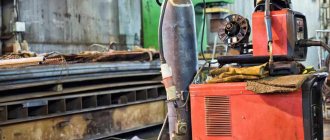
How to weld metal trusses
Welding is carried out either in the factory or at construction and repair sites. In the factory, production of critical structures, such as trusses for covering public and industrial buildings, as well as objects.
As a rule, large-span metal trusses are divided into shipping marks (KM section), which are delivered to the construction and repair site. There they carry out enlarged assembly of shipping stamps, as well as installation according to the developed technology.
The length of shipping stamps usually does not exceed 12 meters; this is necessary for the safe transportation of the shipping stamp by road or otherwise.
Less critical ones, such as trusses for entrance canopies and awnings, are made at the construction site. You can make a simple farm with your own hands, for example for a garage, or for a greenhouse. On the website mrmetall.ru you will find useful information on the choice of steel, selection of electrodes, as well as all the necessary equipment.
Key Benefits
The positive qualities of steel structures include:
- Increased load-bearing capacity. Despite its small size, the structure can withstand high loads. This is due to the increased strength of the metal.
- Increased reliability. At the preliminary stages, accurate calculations are made, which helps to obtain the required performance characteristics.
- Easy to install and transport. Metal elements are much lighter than concrete or stone ones.
- Integrity of metal or seams, allowing the formation of sealed pipelines and tanks.
- Possibility of assembling structures both in industrial conditions and at home.
- Ease of use. As loads increase, the products can be strengthened. They can easily be reconstructed and repaired.
Sequences of operations when welding a metal truss
As when welding any other product, before starting work it is necessary to familiarize yourself with the regulatory documentation for manufacturing and the developed technology in full. With drawings of the KM, KMD section, technological maps, as well as prepare the necessary materials, tools, and organize the workplace.
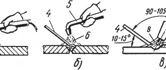
The connection of individual nodes (made from pipes or profiles) leads from the middle node elements to the supporting ones. First, the existing butt joints of the parts are welded, then they move on to T-joints and corner joints. Next, seams with greater thickness are welded. Assembly is carried out using tacks 25-40 mm long. Seams located next to each other must be made after a technological pause.
Fulfillment of this condition is necessary to reduce deformations. Only after the metal has completely cooled down, where a closely spaced seam will be applied. The end of each longitudinal connection (when connecting braces, racks or other units with a gusset) must be brought out to the end of the welded unit by an amount of 2 cm.
Connections used in welding structures
The most common types of seams are:
- Butt joints, characterized by resistance to static and dynamic loads. When forming joints, almost all welding technologies can be used.
- Corner, performing connecting functions. Connections are not capable of transferring workloads. Any welding method is used to form seams.
- Laps used to connect sheet elements. They differ from butt ones in less strength.
- T-bars used when working with spatial structures.
Less common are slotted, end and other connections.
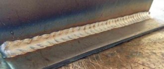
Butt welding joints.
We recommend that you read
Existing types of welded joints
Metal sheet structures.
Metal sheet welded structures are most often used in industry, these include: reservoirs, tanks, bunkers, gas tanks, decks, etc. Sheet metal structures are characterized by a combination of load-bearing and enclosing functions.
Automatic, semi-automatic, electroslag welding is often used for sheets. The parts are longer and are subject to more stringent requirements for joint strength and tightness. You can see the sequence of seams in the image.
Additional Information
Each type of welded structure is connected in its own way. Recommended technologies are indicated in drawings and designs. After welding is completed, the object must acquire the required strength. This places the responsibility on the welder for compliance with the rules and regulations of the process. Special requirements are imposed on metal structures subject to high loads. The service life of the entire facility depends on the quality of welding. After completion of the work, the structures are thoroughly inspected.
Welding methods
Another classification is based on the welding method. There are many welding methods, differing in performance conditions. In production (factory), as a rule, they use:
- Semi-automatic welding in CO2 environment.
- Automatic electric welding in a shielding gas environment (for electric current welding of thick metal, submerged arc welding).
- In installation work, use: Manual arc welding. Automatic and semi-automatic (rare); Manual welding in argon with a non-consumable electrode (mainly used for aluminum and stainless steel).
What types of welded joints exist
A seam formed as a result of crystallization or plastic deformation (pressure welding) of the material of the joined elements. It represents a space at the junction. Welds can be divided into:
- Factory ones.
- Assembly.
They have different designations on the drawings, so carefully study the design documentation before starting work on the construction of this welding structure.
Regardless of whether the seam is factory or assembly, it must meet the requirements and ensure equal strength of the connection. There are many types of welded joints, we suggest you visually familiarize yourself with the most used and common:
- Butt joint.
- Gusset.
- T-joint.
- Lap connection
Tolerances are indicated in regulatory documentation, namely in GOST R 13920-2017.
Standards and regulations
Requirements for the working qualities of welded metal structures used in construction are specified in GOST 27772. SNIP II 23-81 is also an important regulatory documentation.
The requirements specified in these acts apply to the work of professionals. However, you need to familiarize yourself with them before performing welding in a home workshop.
When using a hand-held device, take into account the requirements of GOST 5264-80. Standard 14771-76 describes the features of gas shielded welding. Regulatory documentation also regulates the process of preparing the parts to be joined.
How to make welds correctly
To perform a weld correctly, firstly, you need to familiarize yourself with the regulatory welding and design documentation. The necessary design documentation is presented in the form of a basic set of drawings of the KM brand, and KMD (metal structures, metal detailing structures). In the album of the KM section you will receive general information about the metal welded structures of the construction site (or part of it):
- General form;
- composition of structures (how many beams, columns, trusses, braces, etc. parts);
- main connection points;
- instructions for performing work;
- information about loads on structures;
- specification of rolled metal.
In the KMD section you will find:
- detailed drawings of each metal element;
- detailed components for connecting elements;
- updated specification of rolled metal products.
Read the notes and instructions for performing work on the drawings. It may contain important points, without which the manufactured metal structure will not meet the requirements applied to it.
Assembly and welding of elements must be carried out only if there is a documented technology for welding work for this structure.
Documentation is carried out in the form of technological maps and (or) a production project (PPSD) for welding work. They reflect in detail all questions about the process and materials.
Welding defects
Disadvantages can be internal or external. The first type includes:
- Hot or cold cracks. The former appear during the heating period, the latter during cooling.
- Pores are gas-filled cavities. Appear when the electrode is moved too quickly.
- Foreign inclusions consisting of tungsten, oxides or slag. They arise due to the destruction of the gas cloud protecting the weld pool. When such defects appear, re-cutting of the edges followed by welding is required.
We recommend reading: How to make a potbelly stove for your garage yourself
External defects include:
- Lack of fusion or lack of penetration. When multilayer welding, a seam does not form in some places. This reduces the strength of the structure.
- Burns formed when edges penetrate through. The appearance of a defect is facilitated by slowly moving the electrode at a high current.
- Sagging resulting from the contact of the melt on the main surface.
- Craters formed at arc separation sites. Holes appear when novice welders perform work.
- Oxide films or scales that appear when the weld interacts with air.
- Fistulas formed due to improper preparation of parts.
Types and classification of defects
Quality control of connections eliminates such problems. You can see some defects, such as burns or sagging, during the initial inspection.
Welding sequence
We'll tell you in more detail how to make a seam correctly. To do this, it is important to carry out work in stages:
Stage 1: Familiarization with technical documentation for welding.
Stage 2: Preparation of the workplace, equipment and materials (you can find out which materials to choose for welding on our website mrmetall.ru).
Stage 3: Carrying out the welding work itself.
Stage 4: Non-destructive testing of the resulting seam.
The choice of method depends on many conditions and various factors. The main ones are: the thickness of the elements, the length of the seam made, the type of welding and seam used, the responsibility of the welded structure, etc.
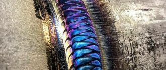
Requirements for welds
Welding today is recognized as the most popular method for the production of various metal structures. Its popularity is explained primarily by the reliability and strength of the final connection. It is quite obvious that welding is widely used in the production of metal products that will bear heavy loads.
But it is worth noting that not all types of welds have durability; the promised durability can only be guaranteed by connections in the manufacture of which all the requirements specified in GOST were met.
The main document that prescribes quality criteria for various types and types of welds is GOST 23118-99. Some additional requirements are specified in the following rules and instructions:
- SP 105-34-96 - consolidated rules that prescribe quality criteria for welds, and also dictate the algorithm for carrying out welding activities;
- VSN 006-89, VBN A.3.1.-36-3-96 – instructions on the technology of welding work;
- VSN 012-88 is an instruction, the content of which consistently indicates all measures to control the quality of work performed.
VT-metall offers services:
The above regulatory documents apply to various welding methods and to various types of seams in welded joints.
Welding technology for metal structures
For seams of varying lengths, it is necessary to use special welding methods.
Short seams with a length of >250 mm are made “overall”. This is when the welder lights an arc and leads it from one edge of the product to the other without stopping during the welding process.
Seams with a length of 1000 mm are called medium. It is correct to make such seams from the center of the product and move to the edges. The best way to carry out 2 welders in parallel. With this approach, two welders work towards the edge of the seam, trying to do it at the same speed.
Long seams are those whose length exceeds 1000 mm. Several different methods are used to join such long seams.
The first is the reverse step method. When using it, the seam is divided into sections, which are welded by welding 150-200 mm of the seam. Stopping and performing the next seam so that its end comes to the beginning of the previous one.
Welding goes in one direction, and the location of the new section goes in the opposite direction. This is easy to understand by looking at the picture below.
Similarly, using the reverse-step method, welding can be done from the middle of the product to the edges. Two welders perform work on their half of the product. This method can be used to brew either a thin product in one pass or a thick one in several passes.
Each welder's area is divided into smaller areas.
The process, as in the previous case, goes in one direction, and the application of new sutures in the other.
Another way is randomly. The seam is divided into equal sections, 5-6 sections. Next, cook the area in the center.
Also applying short-length seams in the opposite direction from the direction of welding. Next, the most distant areas along the edges are welded and the process of the middle sections of the seam is completed. Each of these methods will significantly reduce structural deformation after welding.
Weld quality control
The state standard regulates the mechanical properties of the welded joint, its individual sections, as well as the resulting material. In order to determine how high quality a product is, it is necessary to test it.
GOST prescribes the following methods for determining quality:
- Static
. This method involves a gradual increase in load. It takes a long time to determine quality, since it is necessary to create a constant, prolonged tension. - Dynamic
. In this case, pendulum pile drivers are used. There is no need for long-term observation. A load of maximum force is created in a short period of time. - Fatigue
. The load is created repeatedly. Its strength has different meanings, the number of cycles can reach several million.
Recommended articles
- Welding electrodes: which ones to choose for the job
- Capacitor welding: process features
- Weld defects: we understand the causes, eliminate the consequences
To determine the hardness of weld sections, the Rockwell, Brinnell, and Weckler methods are used.
.
To determine acceptance quality without destructive force, the following methods are used:
- Visual and measuring control
. To assess quality, an external inspection is performed. - Ultrasonic method
. Quality assessment occurs using ultrasonic waves. If there are defects in the material, the defective areas will not reflect the wave. - Capillary method
. In this case, liquids with coloring pigments are used. If the material has microcracks, the liquid will penetrate into them and reveal the presence of a defect through staining. - Pneumatic method
. The presence of defects is determined by supplying air under pressure and a soap solution. Poor quality will be indicated by the formation of bubbles. - The hydraulic method
is similar to the capillary method. Here, too, liquid is poured in, then time is waited. If there are microcracks in the material, they will be filled. Then the specialists will tap the surface with a hammer. If the metal leaks, it means the material has defects. - The magnetic method
is used to control the quality of steel elements. During the test, the material is magnetized and then metal powder is sprayed. If there are no defects, the powder will fall according to the pattern of magnetic fields.
GOST 23118-99 and Consolidated Rules SP105-34-96 indicate the quality requirements for metal products and various types of welds. All parts are examined for the following defects:
- inhomogeneities;
- cracks;
- shells;
- fistulas;
- chips;
- lack of penetration;
- folds
Knowledge of the basic types and connections of welds, as well as the methods and principles of their application, makes it possible to choose the required welding method as competently as possible.