01/24/2022 Author: VT-METALL
From this material you will learn
:
- Requirements for welds
- Differences between welds and joints
- Types of welded joints
- Main types of welds
- Weld quality control
Different types of welds are used in certain conditions to specifically connect parts. Neglecting to choose the most suitable option entails an inevitable loss of connection quality, up to its complete rejection. To prevent this from happening, you need to understand the differences between welds.
Equally important is knowledge of the difference between a weld and a welded joint. In our article we will talk about this, give a typology of connections and seams and outline the quality requirements that are provided by regulations.
Requirements for welds
Welding today is recognized as the most popular method for the production of various metal structures. Its popularity is explained primarily by the reliability and strength of the final connection. It is quite obvious that welding is widely used in the production of metal products that will bear heavy loads.
But it is worth noting that not all types of welds have durability; the promised durability can only be guaranteed by connections in the manufacture of which all the requirements specified in GOST were met.
The main document that prescribes quality criteria for various types and types of welds is GOST 23118-99. Some additional requirements are specified in the following rules and instructions:
- SP 105-34-96 - consolidated rules that prescribe quality criteria for welds, and also dictate the algorithm for carrying out welding activities;
- VSN 006-89, VBN A.3.1.-36-3-96 – instructions on the technology of welding work;
- VSN 012-88 is an instruction, the content of which consistently indicates all measures to control the quality of work performed.
VT-metall offers services:
The above regulatory documents apply to various welding methods and to various types of seams in welded joints.
Differences between welds and joints
A weld and a welded joint are different concepts, but beginners in welding usually confuse these terms. A seam is a place where workpieces meet, which are melted in advance and then cooled. The welded joint consists of three sections that were exposed to high temperature. The latter usually include:
- Seams that appear as a result of melting of the base material. Filler metal may also be added during operation.
- Fusion zone. Geographically, it is located between the weld and the material from which the parts are made. The fusion zone is not subject to high temperatures. It is important to note here that it tends to become saturated with elements that participate in the joining process, electrodes or flux. For this reason, the composition will contain differences from the base metal.
- Thermal affected zone. This is the strip that connects to the fusion zone. At the junction, under the influence of high temperature, the original properties change.
Cutting edges for welding
The weld will be of high quality after carefully carried out preparatory work. They are necessary before welding structures whose element thickness exceeds 5 millimeters. For one-sided welding. The preparatory operation is called edge cutting. The rules and quality of such work are determined by GOST requirements. Removal of contamination from the entire edge should be carried out at a distance of at least 20 millimeters from the future welding site.
Download GOST 5264-80
The main types of this operation are:
- through careful cutting;
- without preliminary cutting;
- the so-called flanging.
Edge preparation and parameters
The flanging is made one-sided for corner joints, double-sided for butt joints.
Preparation is carried out manually (using a file, sandpaper, metal brush) or using electric tools (drills equipped with the necessary attachments, grinders, factory equipment).
For metal with a thickness ranging from 3 mm to 26 mm, a V-shaped single-sided or double-sided type of edge bevel is used. For metal with a thickness of 12 to 60 mm, an X-shaped type of bevel is made.
Edge preparation procedure
A procedure has been established for preparing the material for subsequent work with any type of welded joints. It includes the following items:
- cleaning the edge of the metal (any dirt, deposits, corrosion are removed);
- removing the necessary chamfers (this operation depends on the method used for welding);
- preparation of the gap (size, quality must correspond to a certain type).
Cleaning the edge of the metal
Types of welded joints
Welded joints have some differences, so they are classified into the following types:
- Butt
. A special feature of the connection is the location of the parts in the same plane. - Angular
_ The elements that need to be connected are placed at a certain angle. Most often this angle is 90°. - T-bars
. With this connection, the end of one of the elements is located at an angle of no more than 90°. - Overlapping
. The elements are arranged parallel to each other. - End
. In this case, the two ends are welded into one whole element.
Let us dwell in a little more detail on these types of seams in welded joints.
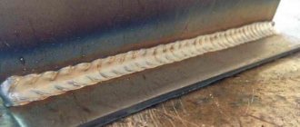
Butt weld
has become widespread in the welding of structures such as pipelines, metal sheets and pipes for various purposes. In this case, the end surfaces are welded. Before you start welding, you need to perform preparatory steps: adjust the surfaces to each other. To achieve maximum accuracy, you can pre-use a weld seam.
Among the advantages of this type, it should be noted that the need to use additional materials is minimal. It is also important that all elements do not have the same thickness.
Important
: during welding, the electrodes must be directed towards the part whose thickness is greater. Thus, heating will be more significant, and parts with the smallest thickness will be protected from burns.
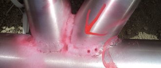
Fillet welds
are used to connect components of various containers, as well as reservoirs. In order for the corner connection to be of the highest quality, the parts should be installed in a “boat” manner.
T-type
has become widespread in the welding of load-bearing structures. Note that it is necessary to thoroughly prepare for T-welding. The main advantages of the T-type type: high strength and the ability to use in difficult places - where welding by other methods is extremely difficult to use.
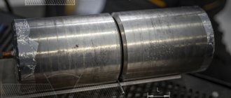
Lap method
used for welding metal sheets. The use of this method is possible if the thickness of the sheets does not exceed 1.2 cm and there are no gaps between the surfaces of the elements. The advantage of the method is its simplicity. A welder does not need to have a high level of skill to get the job done.
Also among the advantages it should be noted that the seams are located at a distance from each other, due to which the strength of the connection significantly increases.
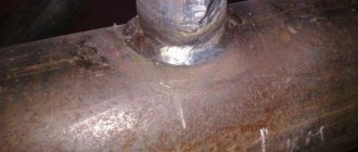
End connections
, as the name implies, are used to connect the ends. The advantage of the method is the possibility of high-quality welding of elements regardless of their thickness. It should also be noted here that the deformation of parts when using this method is minimal.
iSopromat.ru
Welded joints are the most advanced and durable among permanent joints. They are formed under the influence of molecular adhesion forces resulting from strong local heating until the parts melt in the area of their connection or the parts are heated to a plastic state using mechanical force.
The main disadvantages of welded joints: the presence of residual stresses due to non-uniform heating and cooling; the possibility of warping of parts during welding (especially thin-walled ones); the possibility of the existence of hidden defects (cracks, slag inclusions, lack of fusion) that reduce the strength of the joints.
Types of welding are very diverse. Electric welding is the most widely used. There are two main types of electric welding: arc and contact. Depending on the type of heat source used, there is also gas welding. According to the method of protecting the material in the welding zone, welding in argon, submerged arc, vacuum, etc. is used. According to the degree of mechanization, manual, semi-automatic and automatic welding is distinguished.
Depending on the location of the parts being welded, the following types of joints are distinguished: butt, lap, T-joint and corner.
a) Butt joints with different edge preparations
b) Lap joints (flank, frontal, combined)
Figure 15
a) T-joints
b) Corner connections
Figure 16
Butt welds for strength are calculated based on the nominal cross-section of the elements being connected without taking into account the thickening of the seams. To calculate seams, the same dependencies are used as for entire elements.
Tensile (compressive) stress
Figure 17
The permissible stress in welds is marked with a stroke.
Stresses from bending moment in the plane of connected elements
Figure 18
Stress from bending moment in the plane of the connected elements and tensile (or compressive) force
Figure 19
Lap joints are usually made using fillet welds. Based on their location relative to the load, fillet welds are divided into: transverse or frontal, located perpendicular to the direction of force; longitudinal or flank, located parallel to the direction of force; oblique, located at an angle to the direction of force; combined, representing a combination of the listed seams.
Destruction of fillet welds occurs along the smallest section coinciding with the bisector of the right angle. Design seam thickness k∙sin45°=0.7k. The fillet weld experiences a complex stress state. However, in a simplified calculation, such a seam is conventionally designed for shearing.
Figure 20
L is the total length of the seam.
The permissible stresses depend on the permissible stress of the base material.
Depending on the welding method, quality and brand of electrodes φ=0.8…1; φ1=0.6…0.8.
F1∙a1-F1∙a2=0
Figure 21
All fillet welds are calculated using shear stresses only, regardless of their location to the load direction. Combined connections with frontal and flank seams are calculated based on the principle of load distribution proportional to the load-bearing capacity of the individual seams.
If the part being connected is asymmetrical, then the strength calculation is carried out taking into account the load taken by each seam. For example, a corner is welded to a sheet, the resultant load passes through the center of gravity of the cross section of the corner and is distributed along the seams in inverse proportion to arms a1 and a2. Observing the condition of equal strength, the seams are made with different lengths.
When loading a connection with a front seam by a moment of force in the plane of the joint:
Figure 21
T-joints loaded with a bending moment are calculated as cantilever connections, but taking into account the welding features. In the case of welding a beam without beveled edges, welds, like all corner welds, are calculated using shear stresses. The calculated moment of resistance is expressed through the parameters of dangerous sections of welds:
If the beam is welded with beveled edges, then the seams are calculated using normal stresses:
Press connections with guaranteed interference > Contents >
Main types of welds
Types of welds have several classifications:
By position in space
The following classification is adopted here:
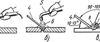
- Bottom welds
are located downward in relation to the specialist. In this case, the molten material cannot flow out of the weld pool. In this case, the rise of slag and gases occurs without obstacles. In bottom welding, the electrode or flame is passed along the joint, and the welder performs transverse movements. - Horizontal seams
are made if vertical elements are to be welded. Welding is performed along a horizontal path: from right to left and from left to right. To prevent the molten metal from flowing down, it is necessary to ensure that the horizontal workpiece is shifted to a level of 1 mm. Particular attention must be paid to welding speed. If welding occurs at a slow pace, there is a risk of drips; if welding occurs at a fast pace, lack of penetration may occur. - In vertical welds
. This type is characterized by the connection of elements from top to bottom and bottom to top. To minimize drips, use low current and weld intermittently. - Overhead welds
are used when the joint is above the welder's head. Surface tension is used to hold the molten material.
By configuration
Types of welds are classified according to their configuration as straight, curved and circumferential. The latter are also called spiral. Note that the configuration of the seams has no relationship with the position of the elements in space.
By degree of convexity
According to the degree of convexity, the seams are:
- Convex (reinforced)
. They are often used to assemble assemblies that will bear high static loads. - Concave (weakened)
. Used for welding metal having a minimum thickness. - Normal (flat)
. The advantage of normal seams is their resistance to impacts that can be destructive. - Special
. These types of welds are shaped like unequal triangles. Most often they are used in corner and T-type connections.
By length
In this case, welds are classified as continuous or intermittent. The latter types are made in segments, the length of which ranges from 10 to 30 cm. When calculating the length of the segment, the total length of the welded joint is taken into account.
The length of welded seams is:
- Chained
. They have one or two sides. The gaps in such a connection should be evenly spaced. - Chess
. In this case, the segments from different sides are shifted in a similar way to a checkerboard pattern. - Dotted
. These seams are used for resistance welding.
Welds are also classified according to their length:
- short
– up to 25 cm; - medium
- from 25 to 100 cm; - long
– length exceeds 1 m.
By number of passes
All types of welds are made in one or more passes. The number of passes is calculated depending on the thickness of the material and the required strength characteristics. Each pass is characterized by the deposition of one bead. With a single-level arrangement, a seam layer is formed.
If the metal has a thickness of up to 5 mm, the connection occurs using one pass. Also, one pass is used if corner joints are created, two passes are used to create butt welds.
In the direction of the acting force and the vector of action of external forces
Here welds are classified as:
- longitudinal (flank)
- the force is made parallel to the joint; - transverse (frontal)
– the direction of the vector occurs at a right angle; - combined
– both of the above methods are used; - oblique
- the force has an acute angle.
By type of welding
The type of welding has a direct relationship with the use of the welding machine. Here are the main types of welds by welding category:
- manual;
- automatic;
- in an environment of inert gases;
- plasma;
- laser;
- gas-flame.
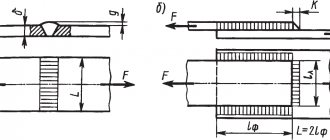
Main types of fillet welds
Figure 529.2 . Main types of welded joints with fillet welds.
a) Frontal seams (2) when joining with an overlap;
b) Flank seams (3) when joining with an overlap;
c) Frontal and flank seams when joining butt joints with overlays (4);
d) Fillet welds when connecting v-tees (butt-to-end) without cutting and with cutting edges;
e) Shear plane (shear) of the flank seam
2.1. Geometric characteristics of fillet welds
One of the main geometric characteristics of a fillet weld, along with the seam length lw , is the seam leg kf . This is due to the fact that no matter what stress-strain state the structural element in question is in, tangential stresses will always act on one of the weld legs. And since shear (shear) resistance is always less than tensile or compression resistance, Table 530.2 considers only one type of stress-strain state - conditional shear.
In this regard, determining the weld leg when calculating fillet welds becomes of great importance. Figure 529.2.e) shows possible geometric shapes of fillet welds (sectional view). As can be seen from this figure, the smallest possible value is taken as the calculated value of the weld leg.
In addition, it is assumed that the destruction of the weld material can occur not along one of the legs, but in a section inclined to the legs at a certain angle or along the fusion boundary. Therefore, when calculating fillet welds, two sections are considered: along the weld metal (1) and along the fusion boundary (2):
Figure 529.3 . Design sections of fillet welds
Accordingly, to determine one of the dimensions of the section under consideration, the coefficients βf - when calculating along the weld metal and βz - when calculating along the fusion boundary. The value of these coefficients can be determined using the following table:
Table 529.1 (according to SP 16.13330.2011 “Steel structures”). Values of coefficients βf and βz for fillet welds
Note : In SNiP II-23-81* “Steel Structures” and in old reference books, the wording of the last paragraph (type of welding) was slightly different, namely: “Manual; semi-automatic (mechanized)…” and so on, which made it possible to easily determine the values of the coefficients for manual welding. Now the wording contains the conjunction “and”, which in my opinion is not entirely correct, since it allows us to consider further conditions as relating to both definitions. In addition, in the indicated sources, the values of the coefficients for manual welding were determined regardless of the position of the weld. Now we see a strange division that allows us to determine only βf when welding in a boat or βz for all other weld positions. In my opinion, this is a clear mistake by the editor, however, SP 16.13330.2011 “Steel Structures” is an updated version of the now defunct SNiP II-23-81* “Steel Structures” and when making calculations, one should be guided by the provisions of the SP. But I’ll still give the corresponding table from the old SNiP:
Table 529.2 . (according to SNiP II-23-81* “Steel structures”)
Weld quality control
The state standard regulates the mechanical properties of the welded joint, its individual sections, as well as the resulting material. In order to determine how high quality a product is, it is necessary to test it.
GOST prescribes the following methods for determining quality:
- Static
. This method involves a gradual increase in load. It takes a long time to determine quality, since it is necessary to create a constant, prolonged tension. - Dynamic
. In this case, pendulum pile drivers are used. There is no need for long-term observation. A load of maximum force is created in a short period of time. - Fatigue
. The load is created repeatedly. Its strength has different meanings, the number of cycles can reach several million.
Recommended articles
- Welding electrodes: which ones to choose for the job
- Capacitor welding: process features
- Weld defects: we understand the causes, eliminate the consequences
To determine the hardness of weld sections, the Rockwell, Brinnell, and Weckler methods are used.
.
To determine acceptance quality without destructive force, the following methods are used:
- Visual and measuring control
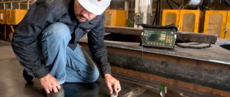
. To assess quality, an external inspection is performed. - Ultrasonic method
. Quality assessment occurs using ultrasonic waves. If there are defects in the material, the defective areas will not reflect the wave. - Capillary method
. In this case, liquids with coloring pigments are used. If the material has microcracks, the liquid will penetrate into them and reveal the presence of a defect through staining. - Pneumatic method
. The presence of defects is determined by supplying air under pressure and a soap solution. Poor quality will be indicated by the formation of bubbles. - The hydraulic method
is similar to the capillary method. Here, too, liquid is poured in, then time is waited. If there are microcracks in the material, they will be filled. Then the specialists will tap the surface with a hammer. If the metal leaks, it means the material has defects. - The magnetic method
is used to control the quality of steel elements. During the test, the material is magnetized and then metal powder is sprayed. If there are no defects, the powder will fall according to the pattern of magnetic fields.
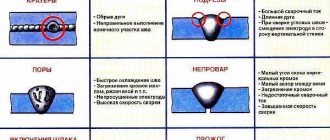
GOST 23118-99 and Consolidated Rules SP105-34-96 indicate the quality requirements for metal products and various types of welds. All parts are examined for the following defects:
- inhomogeneities;
- cracks;
- shells;
- fistulas;
- chips;
- lack of penetration;
- folds
Knowledge of the basic types and connections of welds, as well as the methods and principles of their application, makes it possible to choose the required welding method as competently as possible.