Selecting the optimal equipment is a whole test for people who turn to us for help. Recently, a team of our specialists went to the south of Russia, to the city of Krasnodar, to solve one of these difficult problems.
Below are photos of objects in which our customer specializes.
Welded industrial tank.
Tank for liquids and bulk substances.
Technical task
The company needed to carry out work on welding shells of large diameters (from 3 meters). To achieve maximum seam quality, the process is carried out in the lower position, i.e. movement of equipment along the shell along the seam was excluded.
The shell is on a roller rotator and has an oval shape.
Several difficulties that needed to be resolved:
- The shape of the shell is oval , which means that the gap between the torch and the welding zone will change during rotation.
- Due to the non-ideal shape, during rotation the workpiece moves along the longitudinal axis , respectively, and the welding seam moves either to the left or to the right of the torch.
The welder has to reconfigure the equipment several times during work, and this takes too much time and negatively affects the straightness of the weld. It is necessary to automate this process, thereby increasing the quality and speed of welding.
Welding of thin-walled vessels
Seams of thin-walled vessels are usually made in a protective gas environment. It is recommended to carry out assembly using clamping fixtures - reliable pressing of the welded edges to the lining allows one-sided welding in the fixture without tack welding. When assembling and welding straight seams between sheets and longitudinal seams of shells, uniform and tight pressing of the edges to the lining is carried out using key-type clamping devices. The pressing force is usually 300–700 N per 1 cm of seam length and is created by a hydraulic or pneumatic device (Figure 110). A cradle is fixed to the upper base of the rigid frame 6
with lining 5. The edges to be welded are pressed separately for each sheet through a set of keys
3
mounted on beams
1.
The pressure on the keys is transmitted by pneumatic hoses
2
and is regulated by a gearbox.
Installation and pressing of the sheets is carried out in the following sequence: by turning the eccentric roller 7, the clamps 4 are pulled out from the lining ,
after which the sheet blank is inserted into them until they stop (on the right in the figure) and clamped by supplying air to the hose.
Then the clamps are removed and another workpiece is installed until it stops against the edge of the workpiece and clamped by supplying air to hose 2.
Figure 110 - Device for assembling and welding straight joints of thin-sheet elements
When assembling and welding the longitudinal joints of the shells, the base of the device is made in the form of a console, the clamping beams with keys are fixed to them at one end rigidly, and at the other end by means of hinged bolts.
Longitudinal seams cause a violation of the straightness of the forming thin-walled shells and a decrease in curvature in the seam zone in the cross section (Figure 111). Roller rolling is widely used to correct such welding deformations.
Figure 111 – Nature of deformations of the shell from the longitudinal seam
When making annular joints of thin-walled vessels made of materials that are not very sensitive to stress concentration, the remaining backing rings are used, which facilitate the centering of the edges and their one-sided welding. For a number of high-strength materials, this technique turns out to be unacceptable. In this case, the annular joints are assembled and welded on removable expansion ring pads. However, it must be taken into account that due to the heating of the edges in front of the welding arc, they expand and move away from the backing ring in the radial direction, which can lead to displacement of the edges or the formation of a house. In thin-walled pressure vessels, edge misalignment in the butt weld is a dangerous concentrator and measures must be taken during manufacturing to prevent or eliminate it. To press the edges, external tightening tapes can be used, but they have to be placed at a certain distance from the axis of the joint and movements are only partially prevented. It is more effective to press the edges against the pads with a roller rolling over the joint surface immediately before the welding arc. The clamp prevents the edges from tearing away from the surface of the backing ring at the site where the welded joint is formed. A device for pressing the edges of the shells (Figure 112) is mounted on the welding head console. The pressure rollers rest on both edges to be welded, aligning them and pressing them against the backing ring using a spring.
1 - pressure rollers; 2
- filler wire
Figure 112 – Diagram of a device for pressing the edges to the backing ring in front of the welding head
To weld the shell joint, you can also use a scheme in which the joint is made from inside the shell. In this case, the circumferential weld area is covered by a rigid bandage, which rotates during welding along with the product, and the first pass welding is performed from inside the shell. Compressive stresses arising in the heating zone, trying to increase the length of the free edge of the joint, press it against the outer ring of the bandage.
Deformation from the circumferential weld for most materials reduces the diameter of the shell. This reduction in the weld area can be easily corrected by rolling with rollers. When welding aluminum alloys, the diameter of the shell in the area of the annular weld made on the backing ring may turn out to be not only not smaller, but even larger than the original size. The technique discussed above of pressing the edges against the backing ring with a roller located in front of the welding head (see Figure 112) makes it possible to almost completely prevent such an increase in diameter when welding shell joints made of aluminum alloys.
Particular attention must be paid to the design and technology of making the closing circumferential seam of the vessel. If there are manhole holes or nozzles of significant size, a collapsible expansion ring can be inserted into the vessel. In this case, one-sided welding of the closing seam is performed on a removable lining using conventional technology. The task becomes more complicated if the dimensions of the nozzle openings are small. If the remaining backing ring is too sharp a hub and cannot be used, then it is necessary to carry out one-sided welding by weight. The connection of fittings elements (flanges, fittings) with the vessel wall is usually made butt, allowing connection with fillet welds or projection welding only for materials that are slightly sensitive to stress concentration. Circular butt seams are performed by one-sided welding on a backing with a groove. The type of assembly and welding equipment and the design of the joint are determined by the need to tightly press the edges to the lining, prevent their movement during the welding process and eliminate welding deformations leading to local distortion of the shell shape in the weld zone. Depending on the shape of the surface of the vessel wall (spherical or cylindrical), the material and thickness of the elements being welded, design and technological solutions may be different. For example, when welding a flange into a spherical vessel, it is advisable to use a connection with a collar, shown in Figure 113. The technological collar is designed to transfer the pressing force of the flange to the shell, ensure their alignment and increase the rigidity of the flange edge. The presence of a collar makes it possible to simplify the clamping device, since the clamping force is applied only to the flange, and to prevent displacement of the edges during the welding process, as well as to reduce local distortions of the shell shape resulting from shrinkage of the circular seam.
Figure 113 – Assembling a flange with a shell with a technological collar on the flange
If the size of the vessel or the element into which the reinforcement part is welded is small, it is advisable to weld the circular seam with a stationary welding head while rotating the device with the fixed joint to be welded. When welding reinforcement into a unit of significant size, it is more convenient to make a circular weld with a welding head moving along the surface of a shell element fixed motionless.
In large-scale production of thin-walled vessels (brake tanks, propane cylinders), special semi-automatic installations are used to perform assembly and welding operations. In them, to assemble and weld the longitudinal joint of the shell, it is necessary to perform the following operations: accepting the shell, orienting the joint, pressing it to the lining symmetrically relative to the groove forming the fusion, making a seam, releasing the shell from being clamped and resetting it.
For example, a semi-automatic installation designed for assembling and welding the brake cylinder shell with bottoms runs on ZIL. The bottom flange has a conical surface, which facilitates the mechanization of the assembly operation. In Figure 114, a you can see the location of the grips mounted on the shaft with an incremental rotation of 90°. Orientation and feeding of the shell and two bottoms to position I
performed by the operator, other operations are performed automatically.
Grippers 1
clamp the shell, and pneumatic cylinders with magnetic catchers
2
ensure that the bottoms are pressed into the shell (Figure 114, b).
The assembled vessel is fed to the welding position 11
, where it is released from the clamping after it is grabbed from the ends by the parts of the rotator
4
(Figure 114, c).
The alignment of the electrodes of the welding heads 3
with the plane of rotation of each step of the lap joint is carried out by a finder that turns off the movement of the head in the axial direction at the moment it coincides with the lap step.
Welding is carried out in one revolution with a certain specified overlap. The end of welding serves as a signal to turn on the gripper 1,
release it from the rotator
4
and perform a step turn.
The release of the vessel is achieved by opening the grip under the influence of gravity at position 111
(Figure 114, a).
in g
a – location of grips; b – diagram of the assembly operation; c – diagram of the welding operation, c – machine for welding circumferential seams, d – machine for welding longitudinal seams
Figure 114 – Semi-automatic machine for assembling and welding cylinders
Equipment selection
In order to select the right equipment, you need to make a list of requirements:
- Supports weld tracking system
- Adjustment of the burner position both vertically and horizontally.
- The carriage must be able to perform an oscillating motion in order to fill the joints evenly.
A carriage that fits all of the above points is Rail Titan. That's where we stopped.
Additionally, it is necessary to equip the tractor with:
- seam tracking sensor.
- electric drive to move the burner vertically.
- rail with magnets to install and secure the carriage.
Rail Titan has a built-in oscillation system that allows you to adjust speed, amplitude, delay at extreme points, etc. There is no need to buy anything additional here.
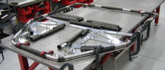
Industrial shell: what is it?
The side part of any cylindrical or conical vessel also represents one or a combination of several shells. When manufacturing nuclear or chemical reactor vessels, according to the requirements of designers, it is necessary to manufacture vessels that are under high pressure and in aggressive environments. Moreover, the length of such a vessel far exceeds the capabilities of foundries and machining machines.
There is a way out - the body is broken into parts. The side walls of the reactor are divided into several (up to ten) rings - cylindrical shells, each of which is sized to be cast and processed separately using existing equipment. After mechanical processing, which brings the dimensions of the body elements to the specified ones, they are connected together on welding stands several tens of meters long. The cover and bottom of the reactor vessel are also divided into segments, which are welded together and, at the last stage, welded to an assembly of several shells, thus achieving the integrity of the vessel.
For vessels of smaller sizes and lower pressure, a different method of making shells is used - they are not cast, but bent from steel sheets on rollers and welded or riveted along the longitudinal seam.
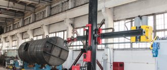
Assembling and installing the carriage
After compiling a list of the required products, we packed everything, arrived at the enterprise and began assembly.
Installing Rail Titan on a guide rail.
Setting up and connecting the carriage.
First, unpack the carriage and guide rail. We install magnets on the rail and fix the tractor on it. Then we connect the additional modules to the carriage that we wrote about above. It is worth noting that everything is done as simply and intuitively as possible. The kit comes with a manual containing detailed pictures for assembly.
Welding carriage assembly diagram.
Finally we connect the cables. It is also impossible to make a mistake here, the cables are marked, each has its own socket. Don’t forget about connecting the control panel - you can then remove it from the carriage (it’s on a magnet) and control the process remotely .
Sheet metal rolling technology
Any type of ductile metal can be rolled. For the manufacture of various containers, steel of various grades is most often used, as well as stainless steel and galvanization. Before you begin directly rolling a metal sheet, the equipment needs to be configured. The rolling radius and other parameters are set for the rolling machine. The whole process consists of several main stages:
- installing the workpiece and securing it in a stationary state;
- gripping the workpiece with rollers;
- rolling the workpiece for uniform deformation.
Rolling of sheet metal carried out using this technology
, allows for the necessary deformation of the metal while maintaining mechanical strength.
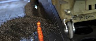
Mode settings
Place the burner and sensor at the required height above the seam. Now it is convenient to use the rack, and then make more precise adjustments using the control panel. We set the required height gap between the burner and the workpiece, align it in the center of the seam, horizontally.
Correct position: the torch follows the seam, the carriage adjusts its position along the required axes, the probe is evenly immersed in the seam.
After this, we proceed to setting up the oscillations. We adjust the amplitude and speed, set the delays at the extreme and central points to a minimum (when using a sensor, the delay on the left and right is at least 0.2 seconds). We start the carriage and the rotation of the shell. We check the operation of the equipment without welding, after which we begin the work process.
Setting the burner position and oscillations.
Preparing the structure for welding.
Characteristics and manufacturing technology of shells
The shell is an open part of a cylindrical or conical shape, used in construction, mechanical engineering and other fields. In cross section it has the shape of a ring. Used as a component, structural unit, workpiece (pipe, ring, rim, short pipe, drum).
Shell elements:
- bottom - sheet structure located at the ends;
- belt - a separate closed element;
- diaphragm - a partition that completely or partially blocks the cross section.
Areas of use
Shells are used in mechanical engineering, rocket, aircraft and shipbuilding, chemical, oil and gas, and defense industries.
Usage:
Result
Photos of the finished, smooth seam indicate that we have successfully completed the task.
Before:
After:
Of course, to obtain an ideal result, it is necessary to more precisely adjust the parameters of the welding source and carriage. But in general, we can say that the configuration coped with the task perfectly. The tractor independently monitors the seam, and the operator does not have to change anything during the process.
I would also like to draw your attention to the fact that this set of equipment will allow you to perform other tasks, for example, welding long straight (longitudinal) seams in any position .
Rolling and bending
Metal rolling
In the procurement area of the plant there is a rolling machine purchased for the manufacture of drying drums and other agricultural machines. Additionally, we provide rolling services for sheet metal with a thickness of 0.8 to 16 mm (for steel grade ST3).
It is possible to roll any rolled metal – pipes, channels, angles, rolled sheets, including flanged sheets. The relative position of the rollers determines the bending radius and the shape of the workpiece. The technology makes it possible to produce shells with a diameter from 300 to 3500 mm.
offers custom-made rolling and bending of sheet metal of any complexity. The workshops are equipped with the latest CNC machines - technological equipment for the production of agricultural equipment.
The high performance of the devices allows you to use their potential to provide metalworking services.
Thanks to the updated main production facilities, the plant offers affordable prices for sheet metal rolling and bending services in Nizhny Novgorod. The cost is affected by the complexity of the parts and the number of bends.
Metal processing time is two days.
To order the services of a bending machine or metal rolling, leave your details on the website. Our manager will call you back at a convenient time.
Requirements
- Mast design: from modules from 12 to 30 m
- Shell width: 3,000 mm
- Shell diameter: from 2,000 to 3,000 mm
- Thickness: from 16 to 50 mm (maximum value)
- Maximum weight of one module: 80 t
- Maximum weight of one shell: 10 t
- Submerged Arc Welding Type: Tandem
- Opening hours: 24 hours a day
Equipment for longitudinal welding of shell
Welding is carried out inside and outside
Girth Welding Equipment: Welding of flanges on shell
Welding is carried out inside and outside
Girth Welding Equipment: Shell Assembly
Welding is carried out inside and outside
Solution for mast section extension line
This welding column configuration is designed for circumferential welding and shell joining and is equipped with two sets of rotators. The maximum permissible diameter is 4000 mm, the maximum length of the first shell is 6000 mm. The welding column performs internal and external circumferential welding. The shell is installed on adjustable rotators “TR 100 Fit up & LP 100”. The movement of the console is motorized. For this type of work, the welding head is rotated at an angle of 90° relative to the axis of the console and can optionally be mounted on a swivel head with a rotation angle of +/- 45°.
Further descriptions and technical solutions are available on request
Interface for operator interaction with the installation
Our installations are equipped with a new welding process control system - 3A
Advanced mobile control panel
- Centralized management via control panel
- Mobile plug&play system (plug and play)
- Convenient and intuitive interface
Automatic installation control
- Welding process control
- Installation cycle management
- Embedded peripherals
Architecture based on a new concept
- Modular flexible solutions
- Full digital control
- Operation and data exchange over the network
Improved Control Panel
- Centralized management via control panel
- Mobile plug&play system (plug and play)
- Convenient and intuitive interface
- Electronic architecture CAN BUS
- Modular architecture
- Operating system WINDOWS CE
- Downloading programs using the USB bus
- Saving default installation configuration settings
- High reliability (numerical control)
- Modern and convenient control using a mobile control panel
- Different levels for operators
- Control of 2 welding heads
The 3A system provides control of a standard welding cycle, including control of various equipment (power supply, wire feed system, console movements) according to programmed parameters. The mobile control panel is equipped with a 10 meter cable, facilitating the operator’s work.
The following information was not included in this description:
- welding equipment and materials
- flux supply system
- tracking system
- remote control system
- additional solutions for welding work
- shell assembly
- production line diagram
Welding process
Based on the requirements of weld thickness and preparation, we suggest the use of Tandem mono submerged arc welding head: single welding wire + single welding wire. This configuration is available for all types of welding installations and provides deposition rates of 20 kg/h with limited capital and training costs. The deposition rate depends on the welding process used and the welding consumables (welding wire and flux). Two devimatic DX7 wire feed units with motor and gearbox,
- Simple and robust mechanical design
- Reliable source of welding current,
- Adjustment of the position of the welding head using two motorized guides in a range of 200 mm,
- Manual monitoring of the welded joint by the operator using the 3A control panel (or optionally using the Trackmatic system)
-The first welding head is equipped with a single wire feed system of Ø 3.2mm or Ø 4mm and is connected to a DC power source. It can work independently or in conjunction with a second head. It is mounted on a manual vertical guide that allows vertical adjustment of the two heads. — The second welding head is usually equipped with a Ø 4 mm single wire feed system and is connected to an AC/DC power source. In this case, it operates in AC mode. It is mounted on a manual horizontal guide, allowing horizontal adjustment of the position of the two heads. In this case, it operates in AC mode. It mainly affects the deposition rate. Reliable operation of welding installations is guaranteed if our instructions and recommendations are followed. Although the standard configuration of the machine is equipped with a tandem head (mono+mono), a small replacement of elements is sufficient to change the configuration to tandem hybrid (mono+double) and tandem twin (double+double) or tandem powder, if such a configuration is required for special types of welding works