The broaching machine is designed for the cleanest possible processing of both the internal and external surfaces of parts of any configuration. There are all kinds of metalworking devices that differ from each other in certain technological features, the most important of which is their intended purpose.
This paragraph implies:
- machines with internal broaching option;
- machines for external broaching.
One of the most common in this family are broaching machines with an internal broaching system. Among all the variety, the most popular is considered to be a broaching machine with a vertical broaching system, which is used for processing both external and internal parts of various parts. The next sign indicating the difference between metal processing machines is the nature of the working movement and its direction.
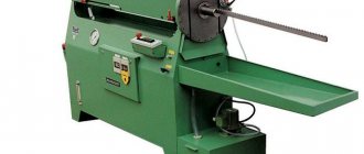
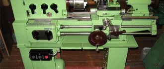
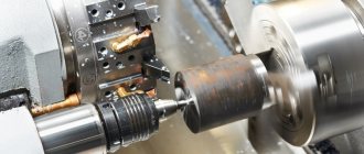
Variant of the appearance of a broaching machine
According to their characteristics, all machines belong to one of the following types:
- with horizontal pulling system;
- with a vertical pulling system;
- a device with a conveyor movement of a rectilinear type, the basis of which is continuity of action;
- a machine that has the option of circular movement of both broaching and the workpiece;
- a machine that has the ability to use various movements of the workpiece and broaching simultaneously, as well as in various combinations.
HORIZONTAL STRAINING MACHINE 7520;
The machine is designed for drawing internal surfaces of various shapes and sizes.
Machine characteristics: nominal traction force 196 kN (20,000 kgf); carriage stroke length: maximum 1600 mm, minimum 230 mm; working speed: maximum 6 m/min; lowest 0.6 m/min; return speed 20 m/min; electric motor power 18.7 kW.
Main components of the machine. Welded frame 1 (Fig. 195) of an elongated box shape carries guides along which carriage 9 moves. Working cylinder 2 with a piston and rod is attached to the end of the frame. The frame contains an emulsion tank and a pump with an electric motor for supplying cutting fluid. An oil reservoir for powering the hydraulic system, a plunger pump and an electric motor are located under the working cylinder. The high-pressure plunger pump NPM-709 is driven by an electric motor. The machine is controlled by a push-button box and end stops. Attached to the supporting part of the machine bed is a trough 7, which has a guide plate along which the steady rest is manually moved. The steady rest holds the broach by the trunnion part not only before starting work, but also during its movement.
Hydraulic system of the machine. After starting the electric motor of the high-pressure pump using the “Start” button, oil from reservoir 19 (Fig. 196) is pumped by gear pump 20 through pipelines 18 and 21 into the reversible spool and through channel 22 into cylinder 15. Then oil from the spool through channel 27 enters into the cylinder chamber 28 and at the same time through channels 32 and 30 - into the right end of valve 33. Cylinder 3 communicates with reservoir 19 through channels 26, 24 and the groove of the reversible spool 25. The sliding block of the plunger pump 12, when the “Start” button is turned on, moves to the right until until the adjustable nut 29 rests against the cylinder body, which will correspond to the zero eccentricity of the plunger pump 12. The sliding block moves to the right due to the difference in the areas of the pistons in cylinders 28 and 15.
At the same time, oil entering through channel 32 into the right chamber of valve 33 moves the plunger to the left. With this position of the plunger, oil lines 4 and 5 will become communicating and the plunger pump will begin to work for itself in the event of inaccuracy in installing the sliding block in the zero position. By turning on the “Working stroke” button, the working stroke solenoid 23 is turned on, which moves the reversing spool plunger to its extreme position. After this, the chambers of cylinders 3 and 28 will communicate through recesses. Due to the difference in the areas of the pistons in cylinders 3 and 15, the sliding block of the plunger pump 12 is shifted to the right up to the thrust screw 13. In this position, the plunger pump will have an eccentricity corresponding to a certain performance. The working speed is set by screw 13 using the steering wheel 14.
Due to the fact that both chambers of the valve 33 are connected by the flow of oil from the gear pump, the plunger, under the action of the spring force, moves to the extreme right position and closes the oil lines 4 and 5. At this time, the oil through the oil lines in and 2 through the differential spool 8 is sucked out of the return cavity working cylinder 1 by a plunger pump and is pumped through oil lines 11 and 7 and a differential spool into the cavity of the working stroke of the cylinder. The differential spool plunger must be in the extreme left position during the stroke. Excess oil resulting from the difference in the volumes of the cavities of the working cylinder is drained through the valve 9 of the differential spool through the tube 10 back into the reservoir 19.
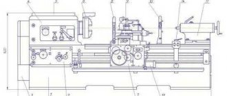
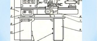
Rice. 195. Horizontal broaching machine 7520:
1 - bed; 2 - hydraulic cylinder; 3 - control mechanism; 4 and 6 — tips of the cooling system; S - cooling system; 7 - trough;
8 — hydraulic drive; 9 - working carriage
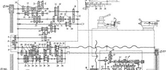
Rice. 196. Diagram of the hydraulic drive of the broaching machine 7520
During the working stroke of the piston, the suction valve 16 is closed by oil pressure from above. The oil pumped by the gear pump at this time flows back into the reservoir through valve 17. At the end of the power stroke, the power stroke solenoid is turned off using a stop mounted on the machine slide. At this moment, the reversible spool, under the action of the spring and levers, is set to the middle position corresponding to the position of the “Stop” button, due to which the plunger pump block takes a neutral position and the oil supply to the working cavity of the cylinder stops. The reverse motion of the machine carriage is carried out after pressing the “Idling” button, which turns on the reverse solenoid 34, and the plunger of the reversing spool 25 occupies the extreme left position and thereby closes the oil line 21. As a result, oil access to the cylinder chambers 28 and 3 is stopped, and cylinder 15 it continues to be pumped. With this position of the reversing spool plunger, chambers 28 and 3 are connected through the plunger grooves to the oil line 24 and reservoir 19.
Under the action of the piston of cylinder 15, the plunger pump block moves to the left until the stop screw 31 is set to the required reverse speed. After moving the differential spool 8 to the extreme right position, the plunger pump through the suction valve 16 pumps oil from the reservoir through oil lines 6 and 2 into the return stroke cavity of the working cylinder 1. The working stroke cavity of the cylinder through oil lines 7 and 2, connected through channel 27 of the reversible spool, is reported with a cylinder return cavity. Due to the difference in the working areas of the piston in the working and idle cavities, the idle speed is much higher than the working speed. At the end of the rapid return stroke, a stop mounted on the carriage turns off the reverse solenoid. The reversing spool in this case is in the neutral position, due to which the sliding block of the plunger pump is also in the neutral position. The work of the machine ends here.
Scheme of lingering operation
Scheme of broaching operation of a horizontal machine
The broaching movement is carried out using a hydraulic drive with two pumps. One of them, with a capacity of 200 l/min, serves to supply oil to the main (working) hydraulic cylinder, the other, with a capacity of 25 l/min, supplies oil to the auxiliary hydraulic cylinder. The hydraulic drive allows three cycles of operation: a full cycle, a simple cycle and an adjustment cycle. Full cycle work is carried out using long broaches (1200-1300 mm) with a rear shank. The broach is installed with the shank into the auxiliary chuck, which receives movement from the rod of the auxiliary cylinder. The broach moves, supported by a roller, to the working chuck. The chuck grabs the front shank of the broach and moves it along with the auxiliary chuck until it opens from the copier, carries out the working and return strokes, after which the auxiliary chuck grabs the rear shank of the broach and moves it to its original position.
A simple cycle is used when using short broaches. In this case, the broach is secured manually in a chuck mounted on a slide that receives horizontal movement from the main hydraulic cylinder along the frame guides. The auxiliary slide does not move during this cycle.
The setup mode is used when setting up the machine. This mode includes the tool movements necessary to prepare the broaching process.
The machine operates as a semi-automatic machine, but when equipped with automated devices for feeding and removing parts, it can operate in an automatic cycle and can be built into automatic lines. The machine is used in large-scale and mass production, and taking into account simple readjustment, it can be used in single and small-scale production.
One of the drawing schemes is shown in Fig. 50. The broach shank 5 is passed through the hole of the workpiece 7 and the sleeve 8 of the device 6 installed in the support plate 9.
The left end of the broach is fixed in an automatic chuck, consisting of a housing 4, a special sleeve 10 with an internal diameter corresponding to the broach, and two crackers 3. In the position shown, spring 2, pushing apart part 1 connected to the rod of the power cylinder, and the housing 4, moves the crackers 3, as a result of which the latter capture the broach shank.
When the broach moves to the left, the hole is machined. During idling, the broach returns to its original position.
Housing 4, approaching device 6, rests against it and stops.
The piston rod and coupling 1, continuing to move and compressing the spring 2, move the sleeve 10 to the right, the crackers 3 fall into the groove a, and the movement stops. Now the broach shank can be freely pulled out of the hole in sleeve 10, inserted into the next part and, having installed it again, begin processing.
The machine operates with a full and simple cycle. With a full forward stroke cycle, the broach is supplied, the working stroke is slow, the adjusted working stroke is a slow working stroke when the calibrating teeth and stops are working. During the reverse stroke, the stroke is slowed down and the broach is retracted. A simple cycle differs from a complete cycle by the absence of feed in and out of the broach.
The full cycle of the machine includes:
- quickly bringing the broach to the working chuck and grabbing it
- slower travel with higher speed (which ensures full use of drive power)
- slow working stroke (to obtain the required roughness when operating the calibrating broach teeth)
- opening the auxiliary chuck and removing the broach from the part
- stopping the machine to unload the part
- reverse movement of the working slide after pressing the “Start cycle” button again
- gripping the workpiece with an auxiliary chuck at the beginning of the return stroke
- slowing down the speed at the end of the return stroke and opening the working chuck
- broach removal using auxiliary slides
- stop
An incomplete cycle is possible without the supply and removal of the broach, when the auxiliary units are not in operation.
To avoid sagging of the free end of the broach when it is fixed in only one of the cartridges, support rollers are provided that can be retracted.
Broaching machine: overview, models, technical characteristics, features of use
The design of a broaching machine is fundamentally different from equipment that performs the functions of crushing, milling, countersinking and planing. In this case, the method of mechanical action may coincide with the listed processing operations, but the principle of exerting force in this case is different. In some aspects, the broaching machine provides higher productivity, but its design features do not allow it to be used in enterprises on a mass scale.
General information about broaching machines
The broaching technology, in its principle of mechanical action, corresponds to the traditional and most common types of metalworking equipment. The difference lies in the very conditions for performing this operation. For example, horizontal broaching machines make it possible to process the internal surfaces of various workpieces with high precision. This equipment is used to form special chamfers in difficult places.
Often, the broaching operation in continuous mass production is the final stage of manufacturing, following the more usual types of processing such as milling or countersinking. Another feature that distinguishes the broaching machine is the use of specific cutting elements. These are so-called broaches, which exert a direct mechanical effect on the material.
Metalworking tool
Bryansk 2014 Contents Introduction 3 Design of a keyed broach 4 Initial data 4 Technical characteristics of the machine 4 Calculation of the broach 5 Selection of an end mill 15 Initial data 15 Justification for the choice of material for the cutting part of the cutter 15 Assignment of the design dimensions of the cutter 15 Selection of an abrasive tool 16 Initial data 16 Technical characteristics of the machine 16 Selection of technical characteristics of the grinding wheel 17 Technical requirements 21 References…………………………………………………………………………………. 22Introduction
Cutting tools are production tools, the final component of metal-cutting machines that are in contact with the workpiece being processed. The purpose of cutting tools is to remove allowance and form the surface and dimensions of the part in accordance with the technical requirements of the working drawing. Despite the wide variety of designs of cutting tools and the specific features of their application, they are characterized by common structural, geometric and other elements, as well as methods of fastening on machines. The purpose of the course design is to consolidate the theoretical foundations and knowledge, learn to independently design complex types of cutting tools.
Specifications
One of the disadvantages of such machines is the dimensions. As a rule, this is an elongated platform in which the workpiece is placed. Dimensional characteristics on average are about 2 m in length, 0.5 m in width and 1.5 m in height. However, the configurations can be different - accordingly, the sizes also differ. The weight is about 500 kg, so before installation it would be a good idea to provide a reliable foundation. From a productivity point of view, the speed of drawing, that is, processing, is also important. For example, a broaching machine from the Flexible Connections enterprise in modification SGP.12.35 provides a working speed of 220 mm/min. In other words, in one minute the equipment can make a cut on an internal surface more than 20 cm long. Here it is also worth considering the maximum processing area, since in most cases, performing the same cutting lines in two approaches is technologically unacceptable. The average length of a single service varies from 4 to 5 m.
WORK PROGRAM OP.07 TECHNOLOGICAL EQUIPMENT work program
Developer: Batalin A.N.___________ teacher of the State Budgetary Educational Institution of Higher Education “Khrenov Forestry College named after G.F. Morozov”.
The program is recommended by the methodological association of teachers of the professional cycle of enlarged groups of specialties 15.00.00 Mechanical Engineering, 09.00.00 “Informatics and Computer Science” of the state budgetary professional educational institution of the Voronezh region “Khrenov Forestry College named after G.F. Morozova"
Protocol No. “1” dated “02” September 2022 CONTENTS
- PASSPORT OF THE DISCIPLINE WORK PROGRAM
- STRUCTURE AND CONTENT OF DISCIPLINE
- CONDITIONS FOR IMPLEMENTATION OF THE DISCIPLINE WORK PROGRAM
- CONTROL AND EVALUATION OF THE RESULTS OF MASTERING THE DISCIPLINE
1. PASSPORT OF THE DISCIPLINE PROGRAM
1.1. Scope of application of the work program
The work program of the discipline “Technological Equipment” is part of the training program for mid-level specialists at the State Budgetary Educational Institution of Higher Education “KhLK im. G.F. Morozov" in accordance with the Federal State Educational Standard in the specialty 02/15/08 Mechanical Engineering Technology.
The work program of the discipline can be used in additional vocational education and training of workers in the field of mechanical engineering and metalworking if they have a secondary (complete) general education. No work experience required.
1.2. The place of the discipline in the structure of the main professional educational program:
The discipline “Technological Equipment” is included in the professional cycle of the professional cycle of the training program for mid-level specialists.
13. Goals and objectives of the discipline - requirements for the results of mastering the discipline:
As a result of mastering the discipline, the student must
- read kinematic diagrams;
- make a rational choice of technological equipment to perform the technological process;
As a result of mastering the discipline, the student must
- classification and designation of metal-cutting machines;
- purpose, scope of application, design, principles of operation, adjustment and technological capabilities of metal-cutting machines, incl. with numerical control (CNC);
- purpose, scope of application, design, technological capabilities of robotic complexes (RTC), flexible production modules (FPM), flexible production systems (FPS).
As a result of mastering the discipline, the student should be able to:
- Select the operating mode of the lathe and CNC lathe;
- Develop calculation and technological maps;
- Develop a control program for a CNC machine;
- Select the operating mode of the CNC milling machine;
As a result of mastering the discipline, the student should know:
- Purpose, scope of application, main components, operating principle and kinematics: lathes, rotary lathes, turret lathes, automatic and semi-automatic lathes, etc.;
- Purpose, operating principle of a vertical drilling machine;
- Purpose, technical characteristics, main components, operating principle, kinematics of a horizontal boring machine;
- Purpose, technical characteristics, main components, operating principle, kinematics of a horizontal milling machine;
- Purpose, technical characteristics, main components, operating principle, kinematics of a vertical milling machine;
- Purpose, technical characteristics, main components, operating principle, kinematics of a multi-purpose machine;
Varieties
There are horizontal, vertical and continuous broaching modifications. The first, already noted option is distinguished by its structural simplicity, therefore it is suitable for performing standard operations for the formation of straight linear cuts with different allowances along the profile. The design of a vertical broaching machine is more complex. This is essentially the same horizontal base, but installed in a vertical position, which provides several advantages. Firstly, the risk of sagging long broaches is eliminated, and secondly, it becomes possible to increase productivity by expanding the production line. As for continuous broach machines, they are mainly used for processing through external surfaces. They are distinguished by higher productivity and the ability to service workpieces in large-scale production.
Horizontal broach
A horizontal broaching machine is used in all cases when there is a need to process the internal or external part of a part, the main movement of which will occur in the linear horizontal direction. Correct movement is achieved through special broaches having different profiles.
Horizontal broaching machine
The working cycle of such a machine is carried out only in a strictly horizontal direction. Removal of chips from the entire area of the workpiece during operation is carried out due to the uniform movement of the teeth over the entire length of the existing broach. In order for the entire process to be fully automated and safe, it makes sense to use a machine for processing and cutting metal with a CNC installed.
Machines with vertical broaching are designed for precision machining of the surfaces of parts of various shapes, made of both ferrous and non-ferrous metals. A vertical broaching machine is used, as a rule, in various industries - such as mechanical engineering - for the purpose of mass production of parts of all possible shapes.
Scheme for setting up a horizontal broaching machine
Where is the machine used?
The very specificity of broaching processing determines non-standard requirements for the result obtained. Accordingly, the areas of use of finished products are not the most common. For example, they are used in the manufacture and modification of firearms. For such operations, planing and broaching machines are used, with the help of which the barrels of machine guns and pistols are produced. This machine is also used in the production of complex external finishing profiles, in cutting keyways and splines, as well as in calibrating multi-faceted and cylindrical holes. A common feature of all types of broaching machining is the wide possibilities of working with figured cuts, and in difficult conditions. In addition, the machine can be used for both non-metallic and solid materials. The fact is that the ability to process atypical workpieces with increased properties of rigidity and hardness is determined by elements of mechanical action, that is, broaches. And they themselves may have different characteristics.
Vertical broach
The operating principle of a vertical broaching machine for internal broaching is based on the fact that the main movement is carried out rectilinearly in the vertical direction by the cutting element of the machine while the workpiece of the future part remains stationary. In addition, when using the screw broaching method on such devices, which is one of the types of internal broaching, additional rotation is also imparted to both the workpiece itself and the cutting element.
Vertical broaching machine
A vertical internal broaching machine has almost the same operating principle as a horizontal one, but with some advantages, which include the following:
- during operation, machines of this class completely eliminate the possibility of sagging and bending of the axis of the broaching element;
- On a machine of this class, it is not difficult to install additional broaches in case of modernization;
- A vertical broaching machine occupies a relatively small working area. This is due to the fact that its entire working cycle occurs strictly in the vertical direction.
- Machines with vertical broaching not only take up less usable space during operation, but are also more convenient than their horizontal “brothers”. These machines are quite often used in production, where mass processing of light and medium-heavy parts is carried out.
Scheme for setting up a vertical broaching machine
Vertical broaching machines also come in both external and internal broaching types. All these types have the following characteristics:
- traction force, depending on the machine model, can range from 50 to 200 kN;
- the maximum maximum amount by which the working carriage moves is in the range from 60 to 160 centimeters;
- the broaching speed during the working cycle can vary from 0.5 to 14 meters per minute.
It is worth noting that both horizontal and vertical broaching machines use a semi-automatic operating principle in their process. The only exception is CNC broaching machines, the entire production process of which is simplified as much as possible and has the highest speed.
Read also: DC motor 220V
Another feature that distinguishes metalworking machines from each other is the number of working carriages available, since there are machines not only with one, but also with several. The next distinguishing feature is position. The simplest is a single-position design, but the most effective are considered to be machines with a multi-position operating principle, since they contain factory-made table devices with a rotary system in their technological equipment.
Manufacturers and models
The Gigant enterprise offers a wide range of models. Its product range includes modifications of broaching machines 7A523, 7A612, 7555, etc. Models differ in processing speed, traction force, power, dimensions and other characteristics. Among foreign manufacturers, the company HOFFMANN Raumtechnik has won trust, which is engaged not only in the development of classic models with vertical and horizontal processing lines. In its family you can find specialized broaching machines. The RAWX-M series models, for example, are designed specifically for finishing grooves and gear joints. The RASA-M modification is distinguished by the presence of four tracks designed for processing spherical grooves of various couplings. For specialized needs, you can look for a suitable model in the family of the Yaroslavl manufacturer Forst Technologie, which is famous for its careful approach to the manufacture of broaching cutting elements of a special design.
Machine cost
The average price range for broaching machines is 2-3 million rubles. In this segment you can find both simple horizontal models and complicated vertical modifications. By the way, it is the vertical broaching machine that is more expensive. The price of the 7A612 model from the one mentioned, for example, is about 2 million. But this is the lowest price level, since the bulk of the equipment is still sold for 2.5-3 million. This is high-tech industrial equipment, which is not only distinguished by high quality processing, but also ergonomic control systems. Suffice it to say that the latest models from major manufacturers are increasingly receiving electronic control panels.
Description of the semi-automatic machine model 7534
Another striking representative of its class is the semi-automatic model 7534 horizontal broaching machine.
Broaching machine 7534
This metal cutting machine, like the previous model, is used for processing not only round and slotted holes, but keyways of various shapes using the horizontal broaching method.
A special feature of this cutting machine is the ability to install additional equipment, with the help of which it becomes possible not only to process the internal, but also the external surface of parts of various sizes and configurations. In addition, the broaching machine 7534 can be equipped with a fully automated system for unloading and loading, which, together with CNC, allows the entire work process to be fully automated.
The horizontal broaching machine has the following features:
- an automated lubrication system, the supply of which to the rubbing parts is carried out in doses;
- built-in alarm system that is triggered in the event of a violation or complete interruption of the lubricant supply;
- axial - piston pump, which ensures the operation of the hydraulic drive during the working cycle;
- an electrical control system for the degree of purification of the working fluid, which consists of a double degree of filtration using a fine filter;
- an air cooling system for oil located in the hydraulics of a metalworking machine.
The 7534 series semi-automatic machine has the following technical characteristics:
- the working stroke of the horizontal guide slides is 160 cm;
- the power of the available traction force is 250 kN;
- the speed of movement of the part during the production cycle reaches 13 meters per minute;
- the maximum external size of the part to be processed is 60 cm;
- nominal weight of the machine is 6250 kg.
Features of operation
Operating personnel are required to place the workpiece in the working niche of the equipment. Next, after launch, the actual processing process begins. A key feature of the functioning of such machines is the fact that the working elements in the form of broaches do not remove chips immediately after cutting, but push them out only after the final exit from the body of the workpiece. Therefore, the range of operator tasks is also expanded due to the need to monitor how correctly machining is performed. On vertical-type broaching machines, the risks of deviations and incorrect cut lines are not so high, since bending of a long workpiece due to its own weight is eliminated.
Safety requirements
When working on broaching machines, it is necessary to strictly observe personal safety measures, which have general principles for all metalworking equipment.
There is a specialized document containing a set of conditions and requirements for broaching machines installed in production. So, for example, safety when cutting on metalworking machines with vertical broaching is ensured by installing a special protective element that protects the operator from injury in cases where the heavy broaching mechanism falls out of the chuck.
During the period of work on horizontal broaching machines, it is mandatory to install a protective folding screen with glass to monitor the process throughout the entire exit area of the broaching element.
It is worth noting that for safety reasons, it is strictly forbidden to install or remove the broach while the metalworking machine is operating. In the case of using a broach whose weight is more than eight kilograms, the use of a special lift is a mandatory requirement.
If you find an error, please select a piece of text and press Ctrl+Enter.