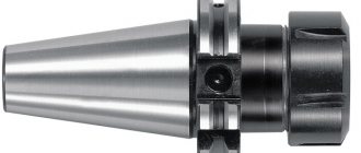
Design of rotating centers
The figure above shows the design of the center intended for fixing the tailstock quill of a lathe into the conical groove. The working part or center (1) rotates thanks to ball bearings (2) and (4); in other design options, needle bearings are used. The axial pressure arising during operation is compensated by the thrust ball bearing (5). Fastening in the quill is provided by a conical shank (3). To accurately determine axial forces, some designs have a built-in device.
More reliable fixation of workpieces, especially when working with heavy parts at high speeds, is ensured by centers built into the quill. This design, shown in the figure below, provides higher fixation rigidity, which is optimal when preparing large-section chips.
There is a specially bored hole in the front part of the quill (1). It contains bearings for the sleeve (4) - thrust (3) located in the front part to absorb axial load and radial (2). A conical hole is machined in the bushing for the center (5). This design can be used to attach a drill or any other axial tool, for which the sleeve is connected with a stopper to the quill.
DIY rotating center for a lathe
Many home craftsmen are thinking about how to make their own metal lathe.
This desire is explained by the fact that with the help of such a device, which will be very inexpensive, you can effectively perform a large range of turning operations, giving metal workpieces the required dimensions and shape.
It would seem much easier to purchase a simple tabletop machine and use it in your workshop, but given the considerable cost of such equipment, it makes sense to spend time making it yourself.
A homemade lathe is quite possible
Using a lathe
A lathe, which was one of the first to appear in the line of equipment for processing parts made of different materials, including metal, allows you to produce products of various shapes and sizes.
Using such a unit, you can turn the external and internal surfaces of the workpiece, drill holes and bore them to the required size, cut external or internal threads, and perform knurling to give the surface of the product the desired relief.
A serial metal lathe is a large device, which is not so easy to operate, and its cost is very difficult to call affordable.
Using such a unit as a desktop equipment is not easy, so it makes sense to make a lathe for your home workshop yourself.
Using such a mini-machine, you can quickly turn workpieces made not only of metal, but also of plastic and wood.
Such equipment processes parts with a round cross-section: axles, tool handles, wheels, structural elements of furniture and products for any other purpose.
In such devices, the workpiece is located in a horizontal plane, while it is given rotation, and the excess material is removed by a cutter securely fixed in the machine support.
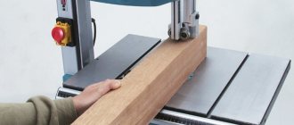
Grooving a brake disc on a homemade lathe
Despite the simplicity of its design, such a unit requires clear coordination of the movements of all working parts in order for processing to be carried out with the utmost precision and the best quality of workmanship.
An example of a homemade lathe with drawings
Let's take a closer look at one of the working options for a lathe assembled on our own, the fairly high quality of which rightfully deserves the closest attention. The author of this homemade product did not even skimp on the drawings, according to which this device was successfully manufactured.
Of course, not everyone needs such a thorough approach to business; often simpler designs are built for home needs, but as a donor for good ideas, this machine is perfectly suited.
DIY lathe
External view of the machine Main components Caliper, tool holder and chuck Side view Tailstock Bottom view of the tailstock Guide shafts Caliper design Engine drive
Drawing No. 1 Drawing No. 2 Drawing No. 3
Structural units
Any lathe, including a homemade one, consists of the following structural elements: a supporting frame - a bed, two centers - a drive and a driven, two headstocks - front and rear, a spindle, a support, a drive unit - an electric motor.
Design of a small-sized metal lathe
All elements of the device are placed on the bed; it is the main load-bearing element of the lathe.
The headstock is a stationary structural element on which the rotating spindle of the unit is located.
In the front part of the frame there is a transmission mechanism of the machine, with the help of which its rotating elements are connected to the electric motor.
It is thanks to this transmission mechanism that the workpiece being processed receives rotation.
The tailstock, unlike the front one, can move parallel to the direction of processing; it is used to fix the free end of the workpiece being processed.
A simple diagram of the components of a homemade woodworking machine will suggest a simple option for making a bed, headstock and tailstock
A homemade metal lathe can be equipped with any electric motor, even if it is not very powerful, but such a motor can overheat when processing large-sized workpieces, which will lead to its stop and, possibly, failure.
Typically, electric motors are installed on a homemade lathe, the power of which is in the range of 800–1500 W. Even if such an electric motor has a small number of revolutions, the problem is solved by choosing an appropriate transmission mechanism.
To transmit torque from such electric motors, belt drives are usually used; friction or chain mechanisms are very rarely used.
Mini-lathes, which are equipped in home workshops, may not even have such a transmission mechanism in their design: the rotating chuck of the unit is fixed directly on the electric motor shaft.
Direct drive machine
In addition, it is necessary to ensure reliable fixation of the part, which is especially important for frontal-type models: with one leading center.
The issue of such fixation is resolved using a jaw chuck or faceplate.
In fact, you can make a lathe with your own hands with a wooden frame, but, as a rule, metal profiles are used for these purposes.
High rigidity of the lathe frame is required so that the accuracy of the location of the driving and driven centers is not affected by mechanical loads, and its tailstock and support with the tool move freely along the axis of the unit.
The use of channels in the manufacture of the frame and headstock of the machine
When assembling a metal lathe, it is important to ensure reliable fixation of all its elements, be sure to take into account the loads to which they will be subjected during operation.
The dimensions of your mini-machine and what structural elements it will consist of will be influenced by the purpose of the equipment, as well as the size and shape of the workpieces that are planned to be processed on it. The power of the electric motor, which you will need to use as a drive, will depend on these parameters, as well as on the size of the planned load on the unit.
Option for bed, headstock and drive
To equip metal lathes, it is not recommended to choose commutator electric motors that differ in one characteristic feature.
The number of shaft revolutions of such electric motors, as well as the centrifugal force that the workpiece develops, increases sharply as the load decreases, which can lead to the part simply flying out of the chuck and can seriously injure the operator.
Such electric motors can be used if you plan to process small and light parts on your mini-machine.
But even in this case, the lathe must be equipped with a gearbox that will prevent an uncontrolled increase in centrifugal force.
Asynchronous three-phase electric motor connected to a 220 Volt network through a capacitor
It has already been proven by practice and design calculations that for turning units that will process metal workpieces up to 70 cm in length and up to 10 cm in diameter, it is best to use asynchronous electric motors with a power of 800 W or more. Engines of this type are characterized by stable rotation speed when there is a load, and when it decreases, it does not increase uncontrollably.
If you are going to make your own mini-machine for metal turning, then you should definitely take into account the fact that its chuck will be affected not only by transverse but also longitudinal loads. Such loads, if a belt drive is not provided, can cause destruction of the electric motor bearings, which are not designed for them.
Scope of application and features
Rotating centers are used in lathes for turning parts at rotation speeds of more than 75 m/min. At this speed, the process of increased wear of the center cone and the center hole of the workpiece begins. A partial way to solve the problem is to use lubricant and carbide tips, but the best option is to use a rotating center.
Main advantages of the equipment:
- Versatility. When using centers with replaceable attachments, parts with different conical axial holes can be processed.
- High load-bearing characteristics, significantly exceeding those of thrust clamps.
- Long service life due to reduced wear.
- Ability to work under high loads.
The main disadvantage is the presence of radial runout. This problem can be solved by using equipment with an acceptable runout indicator, or finishing at low speeds using a fixed center.
The device of the headstock of a lathe (spindle assembly)
The headstock consists of a body (usually cast iron) and a spindle. In machines with a gearbox, shafts, gears and a range switching device are added to provide different cutting torques for processing workpieces, a spindle head lubrication system. The rotational force is transmitted to the part through a pulley on the first shaft. When installing a “cartridge” type spindle, the rotational movement of the cartridge is transmitted from the engine through belts to a pulley mounted on the spindle. When installing an electric spindle, a belt drive and an external motor are not used.
The spindle head body can have different shapes and is usually cast from cast iron. In modern machines, the rigid body of the headstock has precise holes for installing the front and rear spindle bearings; this is achieved by boring the body on a boring machine with a boring bar, followed by control on a measuring machine. It is possible to adjust the spindle axis in the plane of movement of the X axis (for machines with a horizontal bed, this will be a horizontal plane, the direction “towards the operator or away from the operator”). In the vertical plane, accuracy is achieved by scraping
The transmission of rotational motion from the engine to the spindle is most often carried out through V-belts or poly-V-belts and gears. In CNC turning machines, to provide thread cutting functions and maintain a constant cutting speed, an additional sensor is installed - a spindle encoder. The encoder senses the rotation of the spindle and converts it into an electrical pulse sent to the CNC module. In turn, the controller controls the operation of the drive servomotor for smooth (non-discrete) control of the spindle speed.
The spindle assembly, as a rule, has a circulation lubrication system and may have a cooling system. The “cartridge” type spindle is lubricated with grease for the entire service life of the bearings.
The kinematic diagram of the spindle head is usually given in the documentation for a specific machine.
Headstock spindle
The spindle is a hollow shaft made of carbon steel, into the hole of which long workpieces are passed. The spindle is installed in the headstock housing using front and rear bearing units.
The end of the spindle of lathes, depending on the version, complies with GOST 12595-2003 or GOST 26651-85. On modern CNC machines, depending on consumer requests, the geometry of the spindle end can be changed. A clamping device is installed at the end: a lathe chuck, a collet, a faceplate, and a thrust center.
The seating surfaces of the spindle end are processed at least grade 6; during manufacturing, the surface is subjected to hardening and grinding. Otherwise, the radial and axial runout of the installed chuck or other clamping device mounted on the spindle will exceed the permissible values. This will affect the processing accuracy of the workpiece. After installation, the spindle is checked for vibrations and, if necessary, balanced
In this regard, when replacing clamping equipment, the seating surfaces of the spindle must be protected from various types of damage, avoid the presence of chips and dirt, and also check the runout of the newly installed chuck or collet.
example - a “cartridge” type spindle | example - a spindle with shafts and gears of a gearbox |
Accuracy check
Geometric accuracy on CNC lathes is checked using control rolling pins and mandrels. Checking using the grooving method is not included in the checks according to GOST (a workpiece with a diameter of at least 80 mm up to three diameters is clamped into a lathe chuck and the cylindrical surface is turned by moving along the Z axis without pressing the tailstock), is inaccurate and does not reflect the real position of the spindle headstock axis. The grooving results are influenced by many factors and the measurement error will exceed the tolerance value (cutting conditions, cutting edge height and mandrel overhang, condition of the spindle bearings and other kinematics. Permissible deviations are indicated in the appendix to the machine acceptance certificate.
If the results of the accuracy check are unsatisfactory, the cause is identified and eliminated and a retest is carried out.
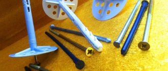
Types of rotating centers
Depending on the shape of the fixing part, two types of rotating centers are available:
- with a working cone for fastening workpieces with center holes;
- with mushroom-shaped attachment for workpieces with an internal hole - pipes, hollow shafts, etc.
By design, the equipment is divided into:
- Center with permanent roller (type A)
- Center with replaceable nozzle (type B)
The cone of the center roller is machined at 60° (version 1) or may have an additional groove for a 30° cone (version 2).
Symbol of equipment: Center A-1-4-NP GOST 8742-75
Type A, version 1 with Morse taper 4 of increased accuracy and normal series.
Table of basic equipment parameters
| Rotating machine centers GOST 8742-75 Type A - with permanent center roller Type B - with an attachment on the center roller | ||||||||||
| Center rotating type-version-Morse taper-series | d | D | L 1 row L 2 row | L 1 row L 2 row | D1 | l1 | ||||
| Rotating center A-1-2-N | Rotating center A-2-2-N | Rotating center B-2-N | 22 | 56 | 160 | 90 | 56 | 24 | ||
| Rotating center A-1-3-N | Rotating center A-2-3-N | Rotating center B-3-N | 25 | 63 | 180 | 185 | 94 | 99 | 63 | 26 |
| Rotating center A-1-4-N | Rotating center A-2-4-N | Rotating center B-4-N | 28 | 71 | 210 | 225 | 101 | 116 | 71 | 30 |
| Rotating center A-1-5-N | Rotating center A-2-5-N | Rotating center B-5-N | 32 | 80 | 240 | 260 | 104 | 124 | 80 | 34 |
| Rotating center A-1-4-U | Rotating center A-2-4-U | Rotating center B-4-U | 36 | 75 | 220 | 235 | 111 | 126 | 75 | 36 |
| Rotating center A-1-5-U | Rotating center A-2-5-U | Rotating center B-5-U | 40 | 90 | 250 | 275 | 114 | 139 | 90 | 45 |
| Rotating center A-1-6-U | Rotating center A-2-6-U | Rotating center B-6-U | 56 | 125 | 340 | 360 | 150 | 170 | 125 | 56 |
Types and purposes of machine centers
According to regulatory documentation, there are two main types of centers:
- Thrust (GOST 13214-79) - in this center the tip and shank have almost equal diameter. The tip is made of carbide or hardened steel.
- Rotating (GOST 8742-75) – differs in that the tip has a larger diameter and a truncated working cone. There are centers with two types of tips: with a centered roller and with a nozzle for it. This device can be used to fix rotating parts with hollow end holes.
If there is a need to process parts at high speeds with a significant thickness of the layer being removed, a rotating rear center is used. If the rotation axes of the workpieces and spindles are different, it is recommended to use a special cone installation during processing.
Features of operation
Here are the basic rules for operating rotating centers necessary for precision machining of parts:
- When choosing the accuracy class of the equipment, it is necessary to leave a margin to cover runout errors due to other reasons - wear of bearings, low rigidity, etc.
- Correct installation of the part is important. The axis of the cone must coincide with the axis of rotation of the workpiece with high accuracy.
- To check the accuracy of the installation, you can place a white sheet of paper under the rotating center and evaluate the alignment. More precise control is carried out using indicators.
- If there is runout, the cone is ground in place and checked using a template. Processing is carried out with a power tool located in the tool holder.
- The beating of the rotating centers leads to the beating of the resulting part relative to the axis. When installing this part on another machine that has a different runout, a deviation from alignment may occur. To eliminate deviations, processing is carried out using a fixed center.
Classification
Depending on the material of the working part, the centers are divided into two versions:
- Version 1 – hardened cone.
- Version 2 – cone made of hard alloys.
The fixed center can be with a full cone or with a cut-off half of the working part. The latter are used when cutting ends, when the cutter needs to reach almost the axis of rotation of the workpiece.
Depending on the shape of the fixing part, fixed centers are divided into equipment:
- with a working cone for fixing parts with centers and without through or blind longitudinal holes;
- with a mushroom-shaped nozzle for fixing parts with an internal hole - pipes, hollow shafts, etc.;
- Thrust centers are available with or without a release nut. The presence of a nut is necessary in cases where a high axial load is applied to the center. The use of a release nut allows you to remove the center from the quill without applying much effort.