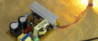
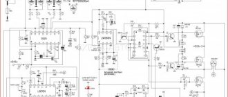
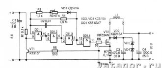
Often the original charger included with the screwdriver works slowly, taking a long time to charge the battery. For those who intensively use a screwdriver, this greatly interferes with their work. Despite the fact that the kit usually includes two batteries (one installed in the tool handle and in use, and the other connected to the charger and in the process of charging), owners often cannot adapt to the operating cycle of the batteries. Then it makes sense to make a charger yourself and charging will become more convenient.
Types of batteries
Batteries are of different types and their charging modes may be different. Nickel-cadmium (Ni-Cd) batteries are a very good source of energy and are capable of delivering high power. However, for environmental reasons their production has ceased and they will become less and less common. Now they have been replaced everywhere by lithium-ion batteries.
Sulfuric acid (Pb) lead gel batteries have good characteristics, but they make the tool heavier and therefore are not very popular, despite their relative cheapness. Since they are gel (the sulfuric acid solution is thickened with sodium silicate), there are no plugs in them, the electrolyte does not leak out of them, and they can be used in any position. (By the way, nickel-cadmium batteries for screwdrivers also belong to the gel class.)
Lithium-ion batteries (Li-ion) are now the most promising and promoted in technology and on the market. Their feature is the complete sealing of the cell. They have a very high power density, are safe to use (thanks to the built-in charge controller!), can be disposed of favorably, are the most environmentally friendly, and are lightweight. They are currently used very often in screwdrivers.
Car battery
An excellent option for powering a screwdriver is a car battery. Especially in cases where repairs are required in an area without electricity. The negative point is that the tool can only be powered from a car battery for a short time, since the vehicle runs the risk of being discharged and will not move. To start a screwdriver, an old analogue car battery is sometimes repurposed. This device is characterized by manual control of current and output voltage.
Upgrade instructions.
- The first step is to select a pair of multi-core cables. It is desirable that they be in windings of different colors for distinction, but of the same cross-section.
- On one side, contacts in the form of “crocodiles” are attached to the wires, on the other, the insulating layer is stripped to 3 centimeters.
- The bare ends are crocheted.
- Next, we begin to disassemble the screwdriver body.
- Find the contact terminals with which the tool was connected to the battery. The bent, stripped ends of the cable are soldered to them. You can do without soldering by using special plastic ties, but professionals prefer a soldering iron.
- The connections must be properly insulated, otherwise there is a risk of a short circuit.
- Both ends of the cable are neatly laid inside the housing and brought out through the handle. You may have to drill additional holes to do this.
- Next you need to assemble the tool.
- After all manipulations, the device is tested. Using “crocodiles”, the screwdriver is connected to the car charger, observing the “+” and “-”.
Such an analog power supply is convenient because it allows you to smoothly adjust the parameters, adapting to any model of screwdriver.
Charge modes
The nominal voltage of the Ni-Cd cell is 1.2 V. The nickel-cadmium battery is charged with a current of 0.1 to 1.0 rated capacity. This means that a battery with a capacity of 5 ampere hours can be charged with a current of 0.5 to 5 A.
The charge of sulfuric acid batteries is well known to all people who hold a screwdriver in their hands, because almost all of them are also car enthusiasts. The nominal voltage of a Pb-PbO2 cell is 2.0 V, and the charging current of a lead sulfuric acid battery is always 0.1 C (a fraction of the current of the nominal capacity, see above).
The lithium-ion cell has a nominal voltage of 3.3 V. The charging current of a lithium-ion battery is 0.1 C. At room temperature, this current can be gradually increased to 1.0 C - this is a fast charge. However, this is only suitable for batteries that have not been over-discharged. When charging lithium-ion batteries, the voltage must be strictly observed. The charge is made up to 4.2 V exactly. Exceeding it sharply reduces service life, lowering it reduces capacity. When charging, monitor the temperature. A warm battery should either be limited by current to 0.1 C, or disconnected until it cools down.
ATTENTION! If a lithium-ion battery overheats when charging above 60 degrees Celsius, it may explode and catch fire! Do not rely too much on the built-in safety electronics (charge controller).
When charging a lithium battery, the control voltage (end of charge voltage) forms an approximate series (the exact voltages depend on the specific technology and are indicated in the battery passport and on its case):
| Number of elements | Denomination eg, B | According to the passport, B | End of charge, V |
| 1 | 3.6 | 3.6 | 4.2 |
| 2 | 7.2 | 7 | 8.4 |
| 3 | 10.8 | 10 | 12.6 |
| 4 | 14.4 | 12 | 16.8 |
| 5 | 18 | 18 | 21.0 |
The charging voltage should be monitored with a multimeter or a circuit with a voltage comparator tuned exactly to the battery used. But for “entry-level electronics engineers,” only a simple and reliable circuit, described in the next section, can really be offered.
Connecting to a computer
Remote power supplies can be designed based on the power supply from a laptop or computer.
From a computer power supply
As a rule, craftsmen use AT-type blocks. They have a power of about 350 Watts and an output voltage of about 12 Volts. These parameters are sufficient for normal operation of the screwdriver. In addition, all technical specifications are indicated on the case, which greatly simplifies the work of adapting the power supply to the instrument. The device can either be borrowed from an old computer or purchased at a computer store. The main advantage is the presence of a power switch, a cooling cooler and an overload protection system.
Next, the sequence of actions is as follows.
- Disassembling the computer case.
- Elimination of power-on protection, which consists of connecting the green and black wires that are present in the specified connector.
- Working with a MOLEX connector. It has 4 wires, two of which are unnecessary. They need to be cut off, leaving only yellow for 12 Volts and black for grounding.
- Soldering to the left wires of an electrical cable. Particular attention should be paid to insulation.
- Disassembling a screwdriver.
- Connecting the instrument terminals to the opposite end of the electrical cable.
- Tool assembly. It is necessary to ensure that the cord inside the screwdriver body is not twisted or pressed too hard.
As a disadvantage, we can highlight the suitability of such a power supply only for tools with an operating voltage of no higher than 14 Volts.
Laptop charger
The power source for the screwdriver can be a charger from a laptop. Its modification is kept to a minimum. It should be noted that any 12-19 Volt device is suitable for use. The algorithm of actions is as follows.
- Preparing the output cord from the charger. Using wire cutters, cut off the connector and strip the ends of the insulation.
- Disassembling the tool body.
- The bare ends of the charger are soldered to the screwdriver terminals, observing polarity. You can use special plastic ties, but professionals advise not to neglect soldering.
- Isolation of connections.
- Assembling the body of a power tool.
- Performance testing.
Remaking a finished charger is simpler and accessible to everyone.
Charger + (Video)
The charger offered below provides the required charging current for any of the listed batteries. Screwdrivers are powered by batteries with different voltages of 12 volts or 18 volts. It doesn’t matter, the main parameter of a battery charger is the charge current. The voltage of the charger when the load is disconnected is always higher than the rated voltage; it drops to normal when the battery is connected during charging. During the charging process, it corresponds to the current state of the battery and is usually slightly higher than the nominal value at the end of charging.
The charger is a current generator using a powerful composite transistor VT2, which is powered by a rectifier bridge connected to a step-down transformer with sufficient output voltage (see table in the previous section).
This transformer must also have sufficient power to provide the required current during long-term operation without overheating the windings. Otherwise it may burn. The charge current is set by adjusting resistor R1 when the battery is connected. It remains constant during the charging process (the more constant the higher the voltage from the transformer. Note: the voltage from the transformer should not exceed 27 V).
Resistor R3 (at least 2 W 1 Ohm) limits the maximum current, and LED VD6 lights up while charging is in progress. Towards the end of the charge, the LED glow decreases and goes out. However, do not forget about precise control of lithium-ion battery voltage and temperature!
All parts in the described circuit are mounted on a printed circuit board made of foil PCB. Instead of the diodes indicated in the diagram, you can take Russian diodes KD202 or D242, they are quite available in old electronic scrap. The parts must be arranged so that there are as few intersections as possible on the board, ideally none. You should not get carried away with high installation density, because you are not assembling a smartphone. It will be much easier for you to solder the parts if there is 3-5 mm between them.
The transistor must be installed on a heat sink of sufficient area (20-50 cm2). It is best to mount all parts of the charger in a convenient homemade case. This will be the most practical solution; nothing will interfere with your work. But here there can be great difficulties with the terminals and connection to the battery. Therefore, it is better to do this: take an old or faulty charger from a friend that is suitable for your battery model, and remake it.
- Open the casing of the old charger.
- Remove all former filling from it.
- Select the following radioelements:
| Pos. | Description |
| VD1-VD4 | 1N4001 rectifier diode |
| VD5 | diode |
| VD6 | VD6 LED, red or green, any type |
| C1 | C1 K50-35 or similar 220-1000 mF from 50 V |
| C2 | C1 K50-35 or similar 220-1000 mF from 50 V |
| R1 | variable resistor 10 kohm, preferably wirewound |
| R2 | resistor MLT-0.25 330 Ohm |
| R3 | resistor MLT-2, 1 Ohm |
| VT1 | transistor KT361V, G |
| VT2 | transistor KT829V (installed on a radiator with an area of 20 - 50 sq. cm |
| T1 | Power transformer 220 V / 24 V, power 100 W |
- Select the appropriate size for the printed circuit board that fits in the case along with the parts from the diagram above, draw its tracks using nitro paint according to the circuit diagram, etch it in copper sulfate and solder all the parts. The heatsink for the transistor must be mounted on an aluminum plate so that it does not touch any part of the circuit. The transistor itself is tightly screwed to it with a screw and an M3 nut.
- Assemble the board in the case and solder the terminals according to the diagram, strictly observing the polarity. Output the wire for the transformer.
- Install a transformer with a 0.5 A fuse in a small suitable housing and provide it with a separate connector for connecting a converted charging unit. It is best to take connectors from computer power supplies, install the male in a case with a transformer, and connect the female to the bridge diodes in the charger.
The assembled device will work reliably if you carefully and thoroughly
Source: instrument-blog.ru
Specifications
When purchasing or assembling a power supply yourself, you always start from the required technical parameters.
- Power. Measured in Watts.
- Input voltage. Domestic networks have 220 Volts. In other countries of the world this parameter is different, for example, in Japan 110 Volts.
- Output voltage. Parameter required for the screwdriver to operate. Typically varies from 12 to 18 Volts.
- Efficiency Reflects the operating efficiency of the power supply. If it is small, it means that most of the converted energy goes to heating the body and parts of the tool.
Scheme, device, repair
Without a doubt, power tools greatly facilitate our work and also reduce the time of routine operations. All kinds of self-powered screwdrivers are now in use.
Let's look at the device, circuit diagram and repair of a battery charger from a screwdriver.
First, let's take a look at the circuit diagram. It is copied from a real charger circuit board.
Charger circuit board (CDQ-F06K1).
The power part of the charger consists of a GS-1415 power transformer. Its power is about 25-26 watts. I calculated using the simplified formula that I already discussed here.
A reduced alternating voltage of 18V from the secondary winding of the transformer is supplied to the diode bridge through fuse FU1. The diode bridge consists of 4 diodes VD1-VD4 type 1N5408. Each of the 1N5408 diodes can withstand a forward current of 3 amperes. Electrolytic capacitor C1 smoothes out voltage ripples after the diode bridge.
The basis of the control circuit is the HCF4060BE , which is a 14-bit counter with elements for the master oscillator. It controls the bipolar transistor of the pnp structure S9012. The transistor is loaded onto the electromagnetic relay S3-12A. The U1 chip implements a kind of timer that turns on the relay for a given charging time - about 60 minutes.
When the charger is plugged in and the battery is connected, the JDQK1 relay contacts are open.
The HCF4060BE chip is powered by a zener diode VD6 – 1N4742A (12V). The zener diode limits the voltage from the mains rectifier to 12 volts, since its output is about 24 volts.
If you look at the diagram, it is not difficult to notice that before pressing the “Start” button, the U1 HCF4060BE chip is de-energized - disconnected from the power source. When the "Start" button is pressed, the supply voltage from the rectifier is supplied to the 1N4742A zener diode through resistor R6.
Next, the reduced and stabilized voltage is supplied to pin 16 of the U1 microcircuit. S9012 , which it controls, also opens
The supply voltage through the open transistor S9012 is supplied to the winding of the electromagnetic relay JDQK1. The relay contacts close and power supply is supplied to the battery. The battery begins to charge. The VD8 diode ( 1N4007 ) bypasses the relay and protects the S9012 transistor from a reverse voltage surge that is formed when the relay winding is de-energized.
The VD5 diode (1N5408) protects the battery from discharge if the mains power is suddenly turned off.
What happens after the contacts of the “Start” button open? The diagram shows that when the contacts of the electromagnetic relay are closed, the positive voltage through the diode VD7 ( 1N4007 ) is supplied to the zener diode VD6 through the quenching resistor R6. As a result, the U1 chip remains connected to the power source even after the button contacts are open.
Replaceable battery.
The GB1 replacement battery is a unit in which 12 nickel-cadmium (Ni-Cd) cells, each 1.2 volts, are connected in series.
In the schematic diagram, the elements of a replaceable battery are outlined with a dotted line.
The total voltage of such a composite battery is 14.4 volts.
There is also a temperature sensor built into the battery pack. In the diagram it is designated as SA1. Its operating principle is similar to the KSD series thermal switches. Marking of thermal switch JJD-45 2A . Structurally, it is fixed to one of the Ni-Cd elements and fits tightly to it.
Self-designed power supplies
Parts for assembly are taken either from various household electrical appliances or energy-saving lamps, or purchased at amateur radio outlets. It is necessary to understand that the electrical circuit will depend on the set of elements. Its assembly requires certain radio engineering knowledge and skills. Graphic versions of the diagrams can be found on the Internet or in specialized literature.
In the simplest case, you will need a ready-made electronic transformer with a power of 60 watts. Experts advise choosing devices from Taschibra or Feron. They don't need modification. The second transformer is assembled manually, for which a ferrite ring is purchased, the dimensions of which are 28x16x9 mm. Next, using a needle file, the corners are turned. Once completed, it is wrapped with electrical tape. For the board, it is better to choose an aluminum plate with a thickness of 3 mm or higher. It will not only perform the load-bearing function of the base for the entire circuit, but will also simultaneously conduct current between the elements of the circuit.
Professionals recommend including an LED light bulb in the design as an indicator. If its size is sufficient, it will also perform the task of illumination. The assembled device is fixed in the battery housing of the screwdriver. When designing, it must be remembered that the dimensions of a homemade power source should in no case exceed the dimensions of the battery pack.
Charging circuit for 18V screwdriver
"People's" charger for a screwdriver
Author: arhimed2007, Published 10/27/2015 Created using KotoEd.
Mrr-meow! Truly, laziness is a brake on progress. I've had a screwdriver lying around in my stash for several years now. Polish (according to the passport), brand “VERTO”, 12 V. I once exchanged it for one of the ancient mobile phones. NEW! PACKAGED. But damn, the battery. From a full charge, after a month of work, it was no longer enough for a dozen screws. A little later, I smelled someone’s discarded filling from a BOSH battery and used it to repackage my battery. But. the same rake! New ones to buy were crushed by a toad. In general, I threw it far away.
So the Polish product lay around for several years. And recently they brought me another 14.4 V Shurik, MATRIX brand, for repair. One of the included batteries died, and most of the batteries were stupidly shorted. As a result, the charger made a noise and burned out so much that the case was deformed and the power supply turned sour. As always, thermal fuse. The second battery turned out to be quite alive.
Naturally, simply restoring the “original” charger is not an option if such defects are possible. At a minimum, overload protection is required. A serious charger with an analyzer was a waste, in addition, smart books said that the simplest design for NiCd is the “drip” charging mode - with a current of 0.1 C, where C is the numerical equivalent of the battery capacity in ampere-hours. In this case, there is no overcharging and the charging current at the end of the process simply compensates for the self-discharge, which is quite high in the cans from Uncle Liao. Thus, the charger simply must be a current stabilizer. It will not allow the power supply to burn if the story with a dead battery repeats itself.
“Native” chargers, as it turned out, do not shine not only in complexity, but also in quality of work. The current-setting resistor in them very often burns through to holes in the board, the current is set at random by Lazar, no protection, no stabilization! Therefore, it was decided to get rid of the original Chinese boards and install a more decent charger instead.
It was decided, as always, to sculpt this device from improvised means, namely old computer hardware. A powerful MOSFET from the motherboard was chosen as a regulating element. The typical current stabilizer circuit on a field-effect transistor was supplemented with an indication of power supply and charging process. This is what happened:
The current stabilizer itself is made of elements VT2, VT3 and current-measuring resistor R5. Zener diode VD2 protects the MOSFET from excess drain-gate voltage. VT1 has an end-of-charge indicator that turns off the red LED HL2 when the voltage at the source of VT3 drops below the opening threshold minus the voltage drop across R4. And this, in turn, happens when the voltage on the battery increases above 15 V. The second LED lights up all the time, indicating the presence of power on the charger. Diode VD1 protects the battery from discharge through the circuit when the power supply is turned off.
The most common MMBT3904 in computer junk (SOT-23 case marked 1Am, t04, p04 or several other options) were taken as VT1, VT2. VT3 - APM2025, although any n-MOSFET used in motherboard power regulators will do. Resistors of size 1206 were taken from old server boards, although smaller ones can be used. It's just easier to make a board for 1206. A capacitor of the same size was also blown out from there. The only output resistor is R5, which I set to 3W. Although, if desired, it can be sculpted from several 1210 hard drives connected in parallel, they will withstand such current.
Advantages and disadvantages of remodeling
Before you start, you should evaluate all the pros and cons of upgrading a tool from a battery to a mains one. The main disadvantage is the loss of mobility, which is not always convenient for working at heights or far from an outlet. As for the advantages, several positive factors can be identified here:
- the problem of suddenly discharged batteries disappears;
- stable torque;
- there is no dependence on temperature conditions (at low values the batteries discharge faster);
- saving money on purchasing new batteries.
Modernization is especially relevant when the “original” batteries are out of order, and new ones are either not on sale, or you have to travel far to get them. It also happens that the purchased device has some problems when receiving energy from the battery. This could be a defect or shortcomings in the design of the model itself. If in principle you are satisfied with the instrument, then it is advisable to remake it and charge it from the mains.
Inverter welding machine
Creating a power source from inverter welding is a more complex type of modernization, since it requires certain theoretical knowledge in the field of electrical engineering and practical skills. Rework entails structural changes to the equipment, which will require the ability to make calculations and draw up diagrams.
Precautionary measures
When working with any electrical device that has undergone modernization, certain safety rules must be followed.
- First of all, when remodeling, you should never neglect good contact insulation and grounding.
- The screwdriver requires short breaks every 20 minutes. During the alteration, the technical characteristics that were laid down by the manufacturer and were designed to operate on battery power changed. An increase in power leads to an increase in the number of revolutions, which causes the tool to heat up. Small breaks will extend the life of the screwdriver.
- It is recommended to regularly clean the power supply from dust and dirt. The fact is that during modernization the seal of the case was broken, so dirt and moisture get inside, especially during open-air work.
- The electrical cable must not be twisted, pulled or pinched. It is imperative to ensure that during operation it is not exposed to any negative influences that could lead to a short circuit.
- Experts do not recommend using a homemade corded screwdriver at a height of more than two meters. Because this automatically entails tension in the wire under its own weight.
- When setting the output parameters, you need to select a current that is 1.6 times greater than the electrical capacity of the battery.
- You should know that when a load is applied to the device, the voltage can drop from 1 to 2 Volts. In most cases this is not important.
These simple recommendations will extend the life of the screwdriver and protect its owner from trouble.
As practice shows, independent modification of the power supply requires experience and good theoretical knowledge of electrical engineering. Therefore, before making a choice, you need to decide whether you are ready to spend your free time drawing up a circuit and assembling a power source, especially if you do not have the proper skills. If you are not sure, then experts advise buying ready-made chargers, especially since their cost on the market is low.
To learn how to turn a cordless screwdriver into a network one, see the following video.
Let's block ads! (Why?)
