With the development of the industrial sector, a large number of technological processes required forced air supply. The household sector has not been left out either. Some types of communications require a regular supply of fresh air.
An elegant solution to this problem was a centrifugal fan, which is capable of autonomously pumping the required amount of air mass. But how is it designed and how does it work? It is these questions that we will examine in detail in our article.
Let's consider the design features of the device, its capabilities, scope of application, and the best manufacturers whose products are presented on the market. We will also give recommendations on choosing the appropriate fan model.
Centrifugal fan design
The design of a centrifugal fan is quite simple. A wheel with blades is located in a housing with inlet and outlet openings. An electric motor is used to operate the device.
The unit works on the following principle: the blades rotate and thereby ensure air movement. Air is sucked in through the inlet under the influence of centrifugal force and pushed out through the outlet.
The direction of movement of air masses at the outlet is perpendicular to the incoming flow. Due to the fact that high pressure is created inside, such fans can move large amounts of air.
This feature allows the use of centrifugal devices in main channels of complex design and long length. Such fans are easy to use and, if used correctly, last for quite a long time.
Rotating blades can be installed perpendicular or parallel to the axis of the circle. With a parallel arrangement, the noise during operation of the device is reduced, but the efficiency does not decrease.
During production, centrifugal fans are equipped with additional functions to perform specific tasks. For example, for use in a room with high temperatures, the device must be equipped with special thermal protection.
If you intend to use it in conditions of high humidity, then the device must have increased resistance to corrosion. Some models even provide explosion protection.
These functions can be combined in one unit, but more often models have one of them.
When selecting a centrifugal model, you must be guided by two important parameters:
- the volume of air masses that pass through the outlet in a certain period of time;
- air pressure at the fan outlet.
Knowing these indicators will help you make the right choice.
Vacuum pumps
A feature of vacuum pumps that determines their design difference from compressors is their high compression ratio.
So, for example, if a vacuum pump sucks out gas (air) at a pressure of 0.05 am
(vacuum 95%) and compresses it to 1.1
am
at the outlet of the pump (an excess pressure of 0.1
am
is necessary to overcome the resistance of the discharge valve and pipeline), then the compression ratio is
while for single-stage piston compressors the compression ratio does not exceed 8.
At such high compression ratios, the volumetric coefficient and performance of the vacuum pump are sharply reduced. Therefore, in order to more fully utilize the working volume of the pump, they strive to minimize the volume of dead space in it. For this purpose, many types of vacuum pumps, such as piston and rotary vane pumps, use the pressure equalization technique, thereby increasing the supply coefficient of the vacuum pumps to V = 0.8-0.9.
Piston vacuum pumps.
These machines are divided into dry and wet. Dry vacuum pumps are used for pumping only gas, wet ones are used for pumping gas and liquid simultaneously, for example, in mixing condensers.
Dry
vacuum pumps are structurally no different from piston compressors.
To increase the volumetric coefficient, some of these machines are equipped with a spool valve mechanism. Using a spool, the dead space of the pump at the end of the compression period is connected to the suction chamber, in which the pressure at the moment is equal to the suction pressure p 1
.
compressed to a pressure p
2 passes from the dead space into a chamber with a pressure
p 1
.
p 1
and
p 2
are equalized ) and gas suction begins almost at the very beginning of the suction stroke of the vacuum pump piston, which increases its performance.
Wet
vacuum pumps do not have a spool distribution mechanism, and their suction and discharge valves are slightly enlarged due to the need to remove a significant amount of liquid, the flow rate of which through the valves should be less than the gas velocity. Therefore, wet vacuum pumps have an increased volume of dead space and create a vacuum that is significantly less than dry vacuum pumps.
Motors for dry piston vacuum pumps are selected taking into account the pump performance based on the maximum compression work corresponding to the residual pressure p 1
= 0.33
am
(provided that the discharge pressure
p 2
is equal to 1
am
).
Rotary vane and liquid ring vacuum pumps.
These pumps are structurally similar to the corresponding compressors (Fig. IV-2 and IV-3). In rotary pumps with pressure equalization, gas bypass is carried out using a special channel connecting the dead space with the chamber of lowest pressure. In this way, a significant increase in the volumetric coefficient of the vacuum pump is achieved. The higher the temperature and partial pressure of the working fluid poured into the pump, the lower the vacuum created by a liquid ring vacuum pump. Therefore, liquid ring vacuum pumps are filled with liquid at the lowest possible temperature.
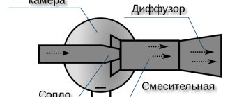
Jet vacuum pumps.
According to the principle of operation, these vacuum pumps are similar to jet pumps for pumping liquids.
As a rule, steam is used as the working fluid in jet vacuum pumps. Steam jet pumps, made of chemically resistant materials, are widely used for suction of acidic vapors. The vacuum created by a single-stage steam jet pump does not exceed 90% absolute. To obtain a deeper vacuum, multi-stage steam jet vacuum pumps are used with condensation of waste steam between stages, consisting of several series-connected steam jet pumps, between which mixing condensers are installed. Condensing the exhaust steam between stages eliminates the need to compress the exhaust steam in each subsequent stage, thereby reducing overall energy consumption.
Technical points
Light materials are used to make the impeller. She may be:
- plastic;
- duralumin;
- aluminum;
- for air transfer of aggressive media - made of stainless steel.
The use of lightweight materials is due to the fact that a powerful engine is not required to rotate the blades. Even industrial air blowers rarely use motors with power exceeding 800 W.
The main technical characteristics of the device depend on:
- direction of rotation of the axis (left or right);
- number of vanes;
- blade shapes (curved or flat);
- installed engine power;
- impeller diameter size;
- body shape (most often, the body is cylindrical);
- protective techniques to reduce injuries: grilles or blinds.
Centrifugal and axial fans are sometimes confused, believing that they are the same thing, but the difference between these devices that enhance air flow is large. They differ in technical characteristics and operating principles.
Principles of installing an exhaust system in a house
To understand exactly how to do home exhaust ventilation with your own hands, you need to understand its structure. Namely, for example, consider a ventilation system made by real professionals in their field.
- The first place is the inlet valve. Its peculiarity lies in the ability to change the amount of air passed through the damper. It must be placed on the north side, since, according to statistics, the wind blows from here most often. At the air inlet to the valve there is a fan, which discharges the flow, forcing the incoming air into the channel. This channel may consist of branches that go to the desired rooms in the house. They are connected by a collector - a distribution compartment.
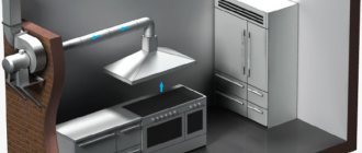
- There is a mixer at the outlet. This is a special camera that is placed in every room. It brings streams of fresh air into the room. There is a recuperator here - a device that serves to heat the air to a comfortable temperature. Heating occurs without significant costs, since in fact there is a normal exchange of energy between hot exhaust carbon dioxide from the room and cooled street air. In the summer, it is recommended to install air conditioners to cool the hot stream coming from the street.
- As for the used air, it passes through the hood and hits the fan, passing through special openings in the form of grilles located in the upper part of the room or on the ceiling. The blades bring the air out into the pipe, which is placed at the same level with the ridge of the roof of your house.
Read also: Power regulator on T160 thyristors
As you can see, installation of such complexity requires the participation of professionals in the work. But there is do-it-yourself supply and exhaust ventilation in the house, which is much easier to do.
Idea No. 2 – Use a motor
In order to make a USB fan from a motor and a CD, it will take a little more time, but you can still easily make such an electrical device with your own hands in an hour.
First, we prepare all the elements of the device. In this case, you will also need an impeller (blades).
To make the impeller, we recommend using an ordinary CD. Draw it into 8 equal parts and carefully cut towards the center. Next, heat the disk (you can use a lighter), and when the plastic becomes more elastic, bend the blades (as shown in the photo).
If the impeller is not bent, no air flow will be created while the disk rotates. Here you need to use moderation so as not to overdo it.
When the blades are ready, move on to creating the main mechanism. We recommend inserting a plastic plug inside the disk, in which you need to make a hole for the motor barrel. Carefully fix the core and move on to creating a USB fan support for the laptop.
Here, as in the previous version, everything depends on your imagination. Of all the available means, the option with wire is the most suitable. When the homemade USB fan is ready, we connect the motor wires to the cord wires, carefully insulate the twist and proceed to test work.
Visual video instructions:
Disk idea
CD idea #2
As you can see, in order to make a fan from a cooler or a motor from a machine, it does not require much time and skills in working with electrical appliances. Even a beginner can cope with this task!
If you don’t have air conditioning or even a household fan at home, and the summer heat doesn’t allow you to live normally, you can use your wits and use old computer parts. Any craftsman can assemble a fan from a cooler, fortunately, the materials for construction are always at hand, and in every home or office you can fish out something useful from computer trash.
How to make a centrifugal fan
From what has been said, the obvious way to achieve this is to remove the tangential fan from the hood, for example. Advantage: Silent operation is ensured. The manufacturer complies with the norms prescribed by the standards, so factory-made devices of the hood class are relatively quiet. We believe that for most readers this is not the best solution to the problem, let’s continue our consideration.
Vacuum cleaner
Inside the vacuum cleaner there is a ready-made centrifugal fan. A big plus is that there is already a ready-made housing that needs to be mounted in the channel on site. Additional benefits include:
- The vacuum cleaner engine is designed for long-term operation. Spins the blade for days on end. The windings are often protected from overheating; in addition, air passes through the channels, cooling the stator.
- The vacuum cleaner engine is designed to overcome significant pneumatic loads. When you disassemble this housewife's assistant yourself, you will see a safety valve inside. Try removing it and blowing it out with your lungs. Does not work? And the engine does this in jest! Pinch the inlet or bend the hose in half. A click coming from the inside of the case indicates activation. We believe that such a force will be more than enough to ventilate the facility.
- Plus - the suction power (in aerowatts) is indicated in the technical specifications, similar to the pressure created. Thus, it is easy to calculate in advance using formulas whether the engine power is sufficient for the selected task. Sometimes manufacturers are so kind that they indicate the flow rate, for example, 3 cubic meters per minute. Anyone can do the math: 180 cubic meters per hour. Thanks to the high power, the flow rate will be maintained despite the turns and bends of the air duct.
Radial
The radial or centrifugal device differs from other types in its unusual spiral design by a casing in which an impeller is located, which compresses the air masses during rotation, moving them in the direction from the center to the peripheral part. The flow enters the casing under the influence of centrifugal forces from the rotation of the wheel with blades.
The blades are welded to the hollow cylinder along its entire perimeter strictly parallel to the axis of rotation using steel disks, their ends are bent inward or outward, which depends on the intended purpose of the device. Rotation can be done in any direction - it depends on how the fan is designed and what tasks are assigned to it (injection or exhaust).
The main components of a radial fan are shown in the drawing below, where 1 is the housing; 2 - impeller; 3 — impeller blades; 4 — fan axis; 5 - bed; 6 - engine; 7 — exhaust pipe; 8 - suction pipe flange
Pros:
- withstands decent overloads;
- energy savings up to 20%;
- small impeller diameter;
- low rotation speeds of the drive shaft.
Minuses:
- high vibrations and noise;
- demands on the quality of manufacturing of rotating parts.
Purpose
Military engineer Sablukov proposed a device for use that has become indispensable in the convection of gas-air mixtures in large volumes.
Rectangular - from three hundred by one hundred and fifty millimeters, to five hundred by one thousand five hundred millimeters, which makes it possible to use in industry. Below is a list of places where radial fans are still used.
Other applications:
- Kitchens, sanitary facilities, bathrooms.
- Harmful production – for quick removal and purification of dirty air.
- In agriculture: on livestock farms, poultry houses, greenhouses.
- Shopping centers, car depots - to remove explosive mixtures.
Device and design
Suction occurs in the direction of the axis of rotation, and discharge occurs tangentially to it, perpendicular to the suction. As the blades rotate, they capture air particles and forcefully throw them out in a centrifugal direction. The fan housing does not allow the flow to dissipate, directing it to the outlet. A vacuum is formed in the area of the central part of the impeller, which is immediately replenished by inflow from the inlet located in the central part of the flat side of the housing.
Peculiarities
The specificity of the operation of centrifugal fans is the ability to reverse the air stream when changing the direction of rotation of the impeller. At the same time, there is practically no difference in pressure; there are only slight differences in parameters due to the use of the reverse sides of the blades. This allows you to install the fan in different parts of the air duct system and provide certain operating modes of the system.
The design of the cochlea fan is quite simple. An impeller is mounted on the drive shaft, rotating inside the housing. There are design options where the impeller does not have its own shaft and is mounted directly on the electric motor shaft. This is typical for small fans. The value is determined by the fan number, which indicates the diameter of the impeller in dm. For example, radial fan No. 4 has an impeller with a diameter of 40 cm.
Impellers, blades
The impeller (impeller) consists of blades that act on certain areas of the air flow and a carousel-type support structure.
There are two types:
- drum type impeller. Outwardly it resembles a squirrel wheel. Used in fans that move a gas-air environment with normal requirements - temperatures up to 80°, no aggressive, flammable, sticky or fibrous inclusions. Fits most fans
- open impeller. It is used much less frequently, since a design of this type is less resistant to mechanical stress. Most manufacturers make such impellers only to order. Used for work as dust devices working with complex materials with fibrous inclusions
Manufacturers rating
Among the large number of manufacturers producing electric fans, the following can be noted with the highest quality products:
- Vitek is a Russian company that has been producing various high-quality equipment for more than two decades. Their range includes household appliances for home and cars, devices for normalizing the microclimate;
- Polaris is an international holding company that produces heating equipment, some household items, water heaters, air conditioners, fans;
- Maxwell is a subsidiary of the Russian holding Golder Electronics. Household appliances are manufactured using modern Chinese technologies, but the quality is quite good, especially for budget models;
- Rolsen is also a Russian company, operating since 1994. The assortment initially consisted of vacuum cleaners, blenders, and steam humidifiers. After being recognized by a large number of consumers, the company expanded its range. They now produce various types of household appliances, including climate control devices;
- KITFORT is a manufacturer tuned to the needs of the consumer market. This is a company whose core values are production and provision of favorable conditions for the purchase of fans;
- Vitesse - this French company initially produced tableware from high-quality stainless steel, then expanded production. Several thousand customers have already been convinced of the excellent quality of the manufactured fans;
- BORK is a German company specializing in the production of premium equipment. The famous German quality does not allow you to doubt a favorable purchase for a minute.
Kinds
The scale of the premises, as well as the level of pollution and heating of the air in them, require the installation of exhaust systems of the appropriate size, power and configuration. Therefore, centrifugal fans come in different types.
Depending on the level of pressure created by the air masses in the exhaust duct, they are classified into fans:
- Low pressure – up to 1 kPa. Most often, their design provides for wide sheet blades that are bent forward to the suction pipe, with a maximum rotation speed of up to 50 m/s. Their scope of application is mainly ventilation systems. They create less noise, so they can be used in rooms where people are constantly present.
- Medium pressure. In this case, the level of load created by the movement of air masses in the exhaust duct can be in the range from 1 to 3 kPa. Their blades can have different angles and tilt directions (both forward and backward), and can withstand a maximum speed of up to 80 m/s. The scope of application is wider than that of low-pressure fans: they can also be installed in process plants.
- High pressure. This technique is used primarily for process plants. The total pressure in the exhaust duct is from 3 kPa. The power of the installation creates a peripheral speed of the suction masses of more than 80 m/s. Turbine wheels are equipped exclusively with backward-curved blades.
Pressure is not the only sign by which radial fans are distinguished. Depending on the speed of the air masses, which is provided by the impeller, they are divided into two classes:
- Class I - indicates that frontally curved blades provide a speed of less than 30 m/s, and back-curved blades provide a speed of no more than 50 m/s;
- Class II includes more powerful units: they provide speed to the driven air masses higher than Class I fans.
In addition, the devices are manufactured with different directions of rotation relative to the suction pipe:
- those oriented to the right can be installed by turning the housing clockwise;
- to the left - counterclockwise.
The scope of application of snails largely depends on the electric motor: its power and the method of attachment to the impeller:
- it can gain speed directly on the engine shaft;
- its shaft is connected to the engine using a coupling and fixed by one or two bearings;
- using a V-belt drive, provided it is fixed by one or two bearings.
Natural and artificial ventilation system
Natural ventilation is created without the use of electrical equipment (fans, electric motors) and occurs due to natural factors - air temperature differences, pressure changes depending on height, wind pressure. The advantages of natural ventilation systems are low cost, ease of installation and reliability due to the absence of electrical equipment and moving parts. Due to this, such systems are widely used in the construction of standard housing and are ventilation ducts located in the kitchen and bathrooms.
The downside of the low cost of natural ventilation systems is the strong dependence of their effectiveness on external factors - air temperature, wind direction and speed, etc. In addition, such systems are, in principle, unregulated and with their help it is not possible to solve many problems in the field of ventilation.
Artificial or mechanical ventilation is used where natural ventilation is insufficient. Mechanical systems use equipment and devices (fans, filters, air heaters, etc.) to move, purify and heat air. Such systems can remove or supply air to ventilated areas regardless of environmental conditions. In practice, in apartments and offices it is necessary to use an artificial ventilation system, since only it can guarantee the creation of comfortable conditions.
Operational Requirements
The use of fans is possible if the following conditions are met:
- The temperature regime of air or gas-air flows (not explosive) in the room should not be higher than 80 degrees, and for double-sided mechanisms - 60 degrees;
- The mechanical impurity should be no more than 1 gram per cubic meter of air;
- The air mass should not contain fibrous particles or sticky substances.
Fan operating principle
It is these indicators that will enable the equipment to work normally, without interruptions or breakdowns.
Centrifugal fan design
The centrifugal design system is a pumping mechanism with a radial architecture that is capable of generating pressure of any range.
Designed for transportation of mono- and polyatomic gases, including chemically “aggressive” compounds.
The design is “clad” with a metal/plastic casing, which is called a protective casing. The shell protects the inner chamber from dust, moisture and other substances that can negatively affect the operation of the unit.
A high-quality ventilation product always has a certain protection class. The degree of protection of the shell (Ingress Protection) is a unified international product quality standard that determines the level of protection of equipment from environmental influences.
The radial type fan develops significantly higher pressure than the axial version. This is due to the communication of a portion of the air entering the drum with energy generated during the transition from the input to the output of the system
The mechanism is driven by an electric motor or an internal combustion engine (typical of industrial fans). The most common method is an electric motor that rotates a shaft with an impeller.
There are several known options for transmitting rotational motion from the motor to the impeller:
- elastic coupling;
- V-belt transmission;
- continuously variable transmission (hydraulic or inductive slip clutch).
Considering the existence of a huge number of manufacturing companies that create unique systems with a wide variety of dynamic parameters, consumers have a fairly extensive range of fans at their disposal.
The housing has two main channels: input and output. The gas mixture enters the first channel, moves into the chamber, is processed there, and then exits into the other
As a result of the intensive work of the developers, we have a wide range of applications for such machines, including:
- ventilation and heating systems in private and multi-storey buildings;
- air supply and purification for non-residential buildings;
- filtration systems in agriculture;
- implementation of technological processes in light and heavy industry of various directions.
There are also options for using blowers in fire suppression systems and ultra-fast air replacement in confined spaces.
Such fans operate with high-temperature gas mixtures, which obliges manufacturers to include in the technical documentation information about the compliance of their equipment with international standards.
The proven and simple design of the centrifugal mechanism has a number of clear advantages:
- high reliability and unsurpassed performance;
- ease and accessibility of equipment maintenance;
- safety of integration and operation of units;
- minimal costs for energy resources and repairs in case of failure.
In addition, blowers have a fairly low noise threshold, which allows them to be used in domestic conditions. Centrifugal fans also have an exceptionally long service life due to the absence of direct contact of the working parts of the mechanism in the working chamber.
Features of the device operating cycle
Let's look at the general operating principle of a centrifugal blower with a radial design. Note that experts distinguish between two main fan designs: with an axial and radial placement of the inlet into which the air flow is sucked.
This primarily affects the option of installing the fan in the system and has virtually no effect on the overall performance.
A radial fan can work both with ordinary air, which it takes from the space, and with flow air that goes through the air duct (the effect of balancing areas with different pressures)
The axial inlet is typical for general purpose positive displacement blowers. Radial placement of the flow inlet is typical for mainline blowers.
During the first stage of the fan operating cycle, air flow moves onto the surface of a rapidly rotating impeller. The impeller blades divide the air into small volumes that move inside the working chamber.
Here the air mass accumulates, that is, the air mass is directly compressed into a small volume.
The design of the unit body itself has its own characteristics.
The two most common hull shapes are known:
- rounded;
- spiral.
The rounded shape of the housing is typical for fans that move a huge amount of air in a short process time. And the spiral shape is inherent in fans, which additionally compress the air volume and generate medium and high pressure.
At the second stage, air is pumped into the working chamber. As is known, at a constant volume, with an increase in the total mass of gas molecules, the number of collisions of molecules increases, and therefore their speed increases. Consequently, the gas pressure also increases.
The shape and number of blades are of great importance. Without exception, all impeller options are tested in wind tunnels to determine optimal operating conditions
At the final stage, the compressed gas is removed from the working chamber to the outlet. Then the air passes into the central air duct and moves in the indicated direction.
The rarefaction process occurs exactly the opposite. Air is taken from an air duct or confined space where a rarefied area needs to be created and discharged into the environment or other confined space.
Some application examples
You can't do without ventilation anywhere. Here are some examples when the operation of other devices is impossible without ventilation:
- on ships (sea and freshwater);
- in the apartment (especially in the kitchen and bathroom);
- in drying chambers of various types.
Marine ventilation devices
There are three types of ship fans installed on boats and ships:
- Blowing. These marine blowers are used when there is a need to pump air into a room and are often equipped with a diffuser. Without ship blowing devices, full operation of the boiler room, supply of supply oxygen to the boiler and cooling of overheated parts is impossible.
- Exhaust. Such axial ship instruments are capable of forcibly removing air from the instruments using the pressurization method. Using exhaust axial ship models, it is possible to quickly clean rooms from smoke and harmful emissions.
- Pumping (carminative). Ship wind turbines are intended for forced circulation of air masses without their extraction and replacement.
Apartment ventilation
In an apartment, proper ventilation in the kitchen, bathroom and restroom is especially important.
- In the kitchen, the exhaust fan is always installed on the hood; it is additionally desirable to install it at the outlet of duct ventilation; both fans for pressurizing air operate almost silently.
- In the restroom, an exhaust device is mounted at the outlet of the duct ventilation and helps remove odors.
- For a bathroom, choosing a ventilation system is more difficult due to high humidity. It is not enough to simply install a hood with duct ventilation; additional installation of capacitors is required.
Ventilation of drying chambers
Special drying chambers are used in everyday life and production. Using drying chambers you can:
- dry clothes;
- prepare dried fruits;
- ensure reduction of wood moisture content.
Drying chambers are capable of quickly drying, but for effective operation they require:
- presence of capacitors;
- a fan that evenly distributes the heated supply air through the drying chamber using the pressurization method.
With full ventilation and uniform distribution of heated supply air, the drying chamber will operate efficiently with minimal energy consumption.
A short overview of the various options for axial fans allows you to determine which device is best selected in terms of size, power consumption and technical characteristics, depending on the planned method of application.
Household fan
The fan is designed to create air flow in the room, ensuring a comfortable stay in the summer.
Household fans are classified by size, performance, number of blades, design and functionality. There are different designs: floor-mounted, table-top and ceiling-mounted. The number of blades can be from three to six. Fans can have rotation speed control and “auto-rotate” functions.
“Auto-rotate” moves the rotor rotation axis in a horizontal plane and is designed to expand the blowing space in a horizontal plane. Fan blades are usually made of plastic, sometimes wood or metal. A plastic fan is lighter, and therefore safer, but not durable. To protect against moving blades, fans are equipped with a grille. They can also be equipped with a timer, backlight, etc.
Fan manufacturers: VENTS Elenberg, Scarlett, Vitek, Systemair, Polaris, ROVEN, etc.
Straight-through or bladeless models
A bladeless fan is a fairly new product in the class of household appliances. They are just exploring the domestic market. The operation of devices of this class is based on Bernoulli's law. Roughly speaking, fast-moving air currents in a carefully thought-out design not only initiate the movement of additional volumes, but also significantly increase the overall efficiency of ventilation.
The device consists of several functional parts.
- A frame, usually in the form of a circle or oval. Its design involves the simultaneous release of air masses from inside the fan housing and the intake of volume from the outside.
- A base that serves as the basis for attaching all components.
- Compact turbine.
- Engine.
The fan works quite simply. The turbine is driven by a motor. It sucks air through holes in the bottom of the device. At the same time, the turbine design creates significant turbulence. As a result, the air is accelerated up to 15 times. The accelerated gas is ejected through the slotted channels of the frame, bending around its surface. At the same time, moving at high speed, it creates a vacuum. This captures air flows from the outside, trying to fill the resulting low pressure zone.
This principle of fan operation has many advantages.
- The air flow can be continuously adjusted.
- All moving parts are hidden inside the housing, which means the device is safe to use.
- It is easy to adjust the airflow direction by simply changing the position of the ring.
- Energy consumption is reduced by up to 20% compared to classic models with equal performance.
We have listed the main types of fans that can be used for ventilation of industrial facilities, government agencies, restaurants and canteens, multi-story buildings in residential areas, which are mounted in inconspicuous places on the back side or on top of flat roof slabs. There are special devices of enormous power that are capable of reliably ventilating objects simultaneously through several air ducts, but this is a completely different topic.
Fans by design
Fans are also divided according to their design method:
- multi-zone
- centrifugal (radial)
- channel
- roof
- ceiling
- axial
- window
Multi-zone fans
Multi-zone centrifugal exhaust fans have a special housing that allows you to connect several suction ducts that extract air from different zones. A zone can be a separate ventilation duct, a room, or even part of a large room. Such fans can be indispensable in facilities where exhaust must be made from several places, but there is only one channel for air exhaust. Multi-zone exhaust fans allow you to optimize the air duct network, reduce the number of expensive shaped products, while using the same type of flexible air ducts.
|
|
Duct fans (direct flow)
Designed for installation in a ventilation duct of round or rectangular cross-section. Fans of this type are installed on the same shaft with an electric motor in a single housing using vibration-isolating gaskets. The fan can be axial, multi-blade or radial, with blades curved both forward and backward, with single or double suction. The casing of duct fans can be made of special plastic, galvanized steel, or even mixed. Due to their small overall dimensions, duct fans can be installed directly in the air duct network, built into ducted ventilation and air conditioning systems and hidden behind a false ceiling or in special vertical cabinets. Any (horizontal, vertical or inclined) position of the fan when installing it is possible. The main advantages of a duct fan are associated with its compactness at significant air flow rates.
Roof Radial Fans (VKR)
The illustration shows typical roof fans. Left – axial, right – radial
Large fans are mounted directly on the roof of a building and usually have a special frame to ensure durability and weather resistance. Due to the fact that they are outdoors for almost their entire service life, they are subject to special requirements for moisture and dust resistance. They are usually made of high-quality steel with a corrosion-resistant epoxy coating or galvanized. There are roof fans for general ventilation systems, as well as special heat-resistant fans for high-temperature systems, for example, smoke removal systems in case of fire, organizing an exhaust hood for a fireplace or gas boiler.
Design and principle of operation of centrifugal fans.
The design of the fan is determined by its aerodynamic design, which is understood as a schematic drawing of its flow path indicating the main dimensions in fractions of the outer diameter of the wheel D2. Fans of different sizes, made according to the same aerodynamic design, belong to the same type and are geometrically similar.
Main elements
are: impeller with blades, inlet pipe (manifold), volute casing, hub, shaft.
Impeller design
have a number of modifications:
- drum impellers are made with blades curved forward. Wheel width = 0.5 diameter. Peripheral speed is allowed up to 30-40 m/s.
- ring impellers have a smaller width. Peripheral speed – 50-60 m/s.
- Impellers with a conical front disc are highly durable and rigid. Peripheral speed up to 85 m/s.
- Three-disc wheels are used on fans with double-sided suction.
- single-disc ones are used for dust fans.
The way the blades are connected to the disks has a significant impact on the rigidity of the structure. The connections used are: solid stamped, spiked, riveted, welded, glued. In one-piece stamped blades and the front disc are stamped from one sheet. The most commonly used connection is a riveted connection. A welded connection is used for large diameter wheels, especially for backward curved blades. In any case, the impellers must be balanced.
Shoulder blades.
The advantage of sheet blades is their simplicity of design. The disadvantage is high rigidity. Profiled shell and shell-frame have high rigidity and operate at peripheral speeds of up to 130 m/s.
Input manifold.
Input devices can be axial or elbow-shaped. Axial pipes are a cylindrical or conical pipe connecting the wheel inlet to the atmosphere or suction pipeline. Elbows are a suction chamber with a rectangular inlet. The flow in such a chamber rotates by 90. The cross-section of the knee-shaped box is usually 2-2.5 times larger than the cross-section of the entrance to the wheel. Frame.
It is made in the form of a special housing with parallel side walls. A conical diffuser with an opening angle of up to 25 can be installed at the exit from the housing. The spiral chambers are either welded or riveted. The housing is removable. In most cantilever fan designs, the housing is suspended from the drive part bracket. This design makes it possible to obtain various assembly patterns by rotating the housing relative to the axis. Only for large structures with double-sided suction, the housing is mounted on a frame or on feet. Due to the conditions of strength and rigidity, the blower fan housing has a frame made of rolled profiles and a casing made of thin sheet metal 4-6 mm. To operate on dusty gases, the housing is made of thicker sheet steel. The most worn sheets are protected with plates made of steel or white cast iron. For chemically active environments, the housing is made of alloy steel X18N9T.
Content
- 1. History
- 2 Construction 2.1 Drive mechanisms 2.1.1 Direct
- 2.1.2 Belt
- 2.4.1 Curved forward
- 3.1 Speed triangle
- 4.1 Air Traffic and Control Association (AMCA)
- 5.1 Impeller inlet
Vents VK 125 – affordable price
Inexpensive among analogues, a supply and exhaust unit for air exchange in residential, commercial and industrial buildings. Belongs to the channel centrifugal type. Durable, moisture and dust resistant plastic is used. Rolling ball bearings are used.
Built-in protection against overheating - through thermal fuses and automatic switching on after a forced stop. Dynamic balancing of the reverse rotor helps reduce vibration and noise. The blades are installed with a reverse bend (backwards).
Pros:
- Low cost, simple design.
- High-quality materials, resistant to moisture and dust.
- Possibility of adjusting the rotation speed.
Minuses:
During installation, you must carefully read the instructions. The device itself is very delicate and fragile.
Design and operating principle
Fan devices used to move various mixtures of gases and air come in several types. The most popular is the centrifugal radial “snail” unit.
It has a rotating wheel assembly and blades attached to it. Different fan models contain different numbers of blades.
The operating principle of the snail hood is as follows:
- Air is sucked into the rotor through the inlet;
- The air mass receives rotational motion;
- Next, by means of the centrifugal force created by the rotating blades, air under pressure is forced to the outlet. It is located in a spiral casing.
Due to the resemblance of the casing to a snail, the fan got its name.
Housing materials
An industrial “snail” can include different materials, depending on the aggressiveness of the application environment. Sheathing of a general-purpose unit operated in non-aggressive gas mixtures with a particle content of less than 0.1 g/cubic meter. m, made from galvanized or carbon steel sheets of different thicknesses. If the environment contains aggressive gas mixtures, is characterized by the presence of active gases and the evaporation of acids, corrosion-resistant steels are used. This type of snail fan operates at temperatures up to 200 degrees Celsius.
There is an explosion-proof version of the hood housing. It is assembled from ductile metals: copper or aluminum alloys. Here, during operation of the hood, sparking, which is the main cause of explosions, is eliminated.
Working wheel
The material requirements for the impeller with blades are plasticity and corrosion resistance. Then the wheel will withstand vibration loads and chemical influences of the environment
To design the shape and number of blades, aerodynamic loads and rotation speed are taken into account. High rotation speed of a large number of slightly curved or straight blades creates a stable air flow
This creates less noise.
Centrifugal exhaust should be classified as equipment with increased vibration. The cause of vibration is the low level of balance of the rotating wheel. Vibration carries with it the following negative factors: destruction of the foundation at the installation site of the equipment and high noise levels. The installation of shock-absorbing springs minimizes vibration. The springs are mounted under the base of the housing. In addition, some models use rubber cushions instead of springs.
Electric motors
Snail-type ventilation equipment is equipped with electric motors with explosion-proof covers and housings. A special protective compound is used to paint engine housings. For the most part, these are asynchronous mechanisms with a fixed rotation speed. They are connected to a single-phase or three-phase network, depending on the design. In special cases, variable speed motors are used.