In the element base of a computer (and not only) there is one bottleneck - electrolytic capacitors. They contain an electrolyte; the electrolyte is a liquid. Therefore, heating such a capacitor leads to its failure, as the electrolyte evaporates. And heating in the system unit is a regular occurrence.
Therefore, replacing capacitors is a matter of time. More than half of the failures of motherboards in the middle and lower price categories are due to dry or swollen capacitors. Even more often, computer power supplies break down for this reason.
Since the printing on modern boards is very dense, replacing capacitors must be done very carefully. You can damage and not notice a small unframed element or break (short) tracks, the thickness and distance between which is slightly greater than the thickness of a human hair. It’s quite difficult to fix something like this later. So be careful.
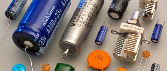
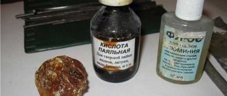
So, to replace capacitors you will need a soldering iron with a thin tip with a power of 25-30 W, a piece of thick guitar string or a thick needle, soldering flux or rosin.
If you reverse the polarity when replacing an electrolytic capacitor or install a capacitor with a low voltage rating, it may well explode. And here's what it looks like:
So, carefully select the replacement part and install it correctly. Electrolytic capacitors are always marked with a negative terminal (usually a vertical stripe of a different color from the body color). On the printed circuit board, the hole for the negative contact is also marked (usually with black shading or solid white). The ratings are written on the capacitor body. There are several of them: voltage, capacity, tolerances and temperature.
The first two are always present, the others may be absent. Voltage: 16V (16 volts). Capacitance: 220µF (220 microfarads). These values are very important when replacing. The voltage can be chosen equal or with a higher nominal value. But the capacitance affects the charging/discharging time of the capacitor and in some cases can be important for a section of the circuit.
Therefore, the capacity should be selected equal to that indicated on the case. On the left in the photo below is a green swollen (or leaking) capacitor. In general, there are constant problems with these green capacitors. The most common candidates for replacement. On the right is a working capacitor, which we will solder.
The capacitor is soldered as follows: first find the legs of the capacitor on the back side of the board (for me this is the most difficult moment). Then heat one of the legs and lightly press the capacitor body from the side of the heated leg. When the solder melts, the capacitor tilts. Carry out a similar procedure with the second leg. Usually the capacitor is removed in two steps.
There is no need to rush, and there is no need to press too hard. The motherboard is not a double-sided PCB, but a multilayer one (imagine a wafer). Overdoing it can damage the contacts on the inner layers of the printed circuit board. So no fanaticism. By the way, long-term heating can also damage the board, for example, lead to peeling or tearing of the contact pad. Therefore, there is no need to press hard with a soldering iron either. We lean the soldering iron and press lightly on the capacitor.
After removing the damaged capacitor, it is necessary to make holes so that the new capacitor can be inserted freely or with little effort. For these purposes, I use a guitar string of the same thickness as the legs of the part being soldered. A sewing needle is also suitable for these purposes, but needles are now made of ordinary iron, and strings are made of steel. There is a chance that the needle will get caught in the solder and break when you try to pull it out. And the string is quite flexible and steel and solder adhere much worse than iron.
When removing capacitors, solder most often clogs the holes in the board. If you try to solder the capacitor in the same way that I advised you to solder it, you can damage the contact pad and the track leading to it. Not the end of the world, but a very undesirable occurrence. Therefore, if the holes are not clogged with solder, they simply need to be expanded. And if you do, then you need to press the end of the string or needle tightly to the hole, and on the other side of the board, lean the soldering iron against this hole. If this option is inconvenient, then the soldering iron tip should be leaned against the string almost at the base. When the solder melts, the string will fit into the hole. At this moment you need to rotate it so that it does not grab the solder.
After obtaining and expanding the hole, it is necessary to remove excess solder from its edges, if any, otherwise, during soldering of the capacitor, a tin cap may form, which can solder adjacent tracks in those places where the seal is dense. Pay attention to the photo below - how close the tracks are to the holes. Soldering this is very easy, but difficult to notice, since the installed capacitor interferes with the view. Therefore, it is very advisable to remove excess solder.
If you don’t have a radio market nearby, then most likely you can only find a used capacitor for replacement. Before installation, its legs should be treated, if necessary. It is advisable to remove all solder from the legs. I usually coat the legs with flux and tin them with a clean soldering iron tip, the solder collects on the soldering iron tip. Then I scrape the legs of the capacitor with a utility knife (just in case).
That's all, actually. We insert the capacitor, lubricate the legs with flux and solder. By the way, if you use pine rosin, it is better to crush it into powder and apply it to the installation site than to dip a soldering iron in a piece of rosin. Then it will work out neatly.
Replacing a capacitor without desoldering it from the board
Repair conditions vary, and changing a capacitor on a multilayer (PC motherboard, for example) printed circuit board is not the same as changing a capacitor in a power supply (single-layer, single-sided printed circuit board). You must be extremely careful and careful. Unfortunately, not everyone was born with a soldering iron in their hands, and repairing (or trying to repair) something is very necessary.
As I already wrote in the first half of the article, most often the cause of breakdowns is capacitors. Therefore, replacing capacitors is the most common type of repair, at least in my case. Specialized workshops have special equipment for these purposes. If you don’t have it, you have to use conventional equipment (flux, solder and soldering iron). In this case, experience helps a lot.
And if there is no experience, then an attempt at repair may well end in failure. Just for such cases, I hasten to share a method for replacing capacitors without desoldering them from the printed circuit board. The method is outwardly rather inaccurate and to some extent more dangerous than the previous one, but for personal use it will do.
The main advantage of this method is that the contact pads of the board will have to be subjected to much less heat. At least twice. Printing on cheap motherboards quite often peels off due to heat. The tracks come off, and fixing this later is quite problematic.
The disadvantage of this method is that you still have to put pressure on the board, which can also lead to negative consequences. Although from my personal experience I have never had to press hard. In this case, there is every chance of soldering to the legs remaining after mechanical removal of the capacitor.
So, replacing a capacitor begins with removing the damaged part from the motherboard.
You need to place your finger on the capacitor and, with light pressure, try to swing it up and down and left and right. If the capacitor swings left and right, then the legs are located along the vertical axis (as in the photo), otherwise along the horizontal axis. You can also determine the position of the legs by the negative marker (a strip on the capacitor body indicating the negative contact).
Next, you should press the capacitor along the axis of its legs, but not sharply, but smoothly, slowly increasing the load. As a result, the leg is separated from the body, then we repeat the procedure for the second leg (press from the opposite side).
Sometimes the leg is pulled out along with the capacitor due to bad solder. In this case, you can slightly widen the resulting hole (I do this with a piece of guitar string) and insert a piece of copper wire there, preferably the same thickness as the leg.
Half the job is done, now we move directly to replacing the capacitor. It is worth noting that the solder does not stick well to the part of the leg that was inside the capacitor body and it is better to bite it off with wire cutters, leaving a small part. Then the legs of the capacitor prepared for replacement and the legs of the old capacitor are treated with solder and soldered. It is most convenient to solder the capacitor by placing it on the board at an angle of 45 degrees. Then you can easily stand him at attention.
The resulting appearance is, of course, unaesthetic, but it works and this method is much simpler and safer than the previous one in terms of heating the board with a soldering iron. Happy renovation!
In the element base of a computer (and not only) there is one bottleneck - electrolytic capacitors. They contain an electrolyte; the electrolyte is a liquid. Therefore, heating such a capacitor leads to its failure, as the electrolyte evaporates. And heating in the system unit is a regular occurrence.
Therefore, replacing capacitors is a matter of time. More than half of the failures of motherboards in the middle and lower price categories are due to dry or swollen capacitors. Even more often, computer power supplies break down for this reason.
Since the printing on modern boards is very dense, replacing capacitors must be done very carefully. You can damage and not notice a small unframed element or break (short) tracks, the thickness and distance between which is slightly greater than the thickness of a human hair. It’s quite difficult to fix something like this later. So be careful.
So, to replace capacitors you will need a soldering iron with a thin tip with a power of 25-30 W, a piece of thick guitar string or a thick needle, soldering flux or rosin.
If you reverse the polarity when replacing an electrolytic capacitor or install a capacitor with a low voltage rating, it may well explode. And here's what it looks like:
So, carefully select the replacement part and install it correctly. Electrolytic capacitors are always marked with a negative terminal (usually a vertical stripe of a different color from the body color). On the printed circuit board, the hole for the negative contact is also marked (usually with black shading or solid white). The ratings are written on the capacitor body. There are several of them: voltage, capacity, tolerances and temperature.
The first two are always present, the others may be absent. Voltage: 16V (16 volts). Capacitance: 220µF (220 microfarads). These values are very important when replacing. The voltage can be chosen equal or with a higher nominal value. But the capacitance affects the charging/discharging time of the capacitor and in some cases can be important for a section of the circuit.
Therefore, the capacity should be selected equal to that indicated on the case. On the left in the photo below is a green swollen (or leaking) capacitor. In general, there are constant problems with these green capacitors. The most common candidates for replacement. On the right is a working capacitor, which we will solder.
The capacitor is soldered as follows: first find the legs of the capacitor on the back side of the board (for me this is the most difficult moment). Then heat one of the legs and lightly press the capacitor body from the side of the heated leg. When the solder melts, the capacitor tilts. Carry out a similar procedure with the second leg. Usually the capacitor is removed in two steps.
There is no need to rush, and there is no need to press too hard. The motherboard is not a double-sided PCB, but a multilayer one (imagine a wafer). Overdoing it can damage the contacts on the inner layers of the printed circuit board. So no fanaticism. By the way, long-term heating can also damage the board, for example, lead to peeling or tearing of the contact pad. Therefore, there is no need to press hard with a soldering iron either. We lean the soldering iron and press lightly on the capacitor.
After removing the damaged capacitor, it is necessary to make holes so that the new capacitor can be inserted freely or with little effort. For these purposes, I use a guitar string of the same thickness as the legs of the part being soldered. A sewing needle is also suitable for these purposes, but needles are now made of ordinary iron, and strings are made of steel. There is a chance that the needle will get caught in the solder and break when you try to pull it out. And the string is quite flexible and steel and solder adhere much worse than iron.
When removing capacitors, solder most often clogs the holes in the board. If you try to solder the capacitor in the same way that I advised you to solder it, you can damage the contact pad and the track leading to it. Not the end of the world, but a very undesirable occurrence. Therefore, if the holes are not clogged with solder, they simply need to be expanded. And if you do, then you need to press the end of the string or needle tightly to the hole, and on the other side of the board, lean the soldering iron against this hole. If this option is inconvenient, then the soldering iron tip should be leaned against the string almost at the base. When the solder melts, the string will fit into the hole. At this moment you need to rotate it so that it does not grab the solder.
After obtaining and expanding the hole, it is necessary to remove excess solder from its edges, if any, otherwise, during soldering of the capacitor, a tin cap may form, which can solder adjacent tracks in those places where the seal is dense. Pay attention to the photo below - how close the tracks are to the holes. Soldering this is very easy, but difficult to notice, since the installed capacitor interferes with the view. Therefore, it is very advisable to remove excess solder.
If you don’t have a radio market nearby, then most likely you can only find a used capacitor for replacement. Before installation, its legs should be treated, if necessary. It is advisable to remove all solder from the legs. I usually coat the legs with flux and tin them with a clean soldering iron tip, the solder collects on the soldering iron tip. Then I scrape the legs of the capacitor with a utility knife (just in case).
That's all, actually. We insert the capacitor, lubricate the legs with flux and solder. By the way, if you use pine rosin, it is better to crush it into powder and apply it to the installation site than to dip a soldering iron in a piece of rosin. Then it will work out neatly.
Where to begin
First, you need to decide for what purpose you need soldering. For amateur radio, this is an entry-level level; for soldering wiring and a simple level, more professional tools are needed. And to repair and solder SMD and BGA microcircuits, you will have to learn all the basics of soldering and purchase special tools and consumables.
Choosing the Right Soldering Kit
Solders come in different types and diameters.
A large solder diameter is convenient for soldering wires, and small diameters are suitable for spot soldering SMD components or connectors. Solders also come with or without rosin. With rosin, solder is very convenient. It is easiest to use it on a soldering iron tip.
Starter Kit
For radio amateurs, stores sell everything at once in one pack. Such sets are the cheapest, since everything will cost more separately. For example, there are sets with a soldering iron and tips, as well as tweezers.
Soldering iron or station
For soldering radio components and wires, a simple soldering iron with a copper tip is sufficient. But for more advanced soldering you will need a station. A soldering station usually consists of a hair dryer and a soldering iron. Using a hair dryer, you can solder SMD components, and you will be able to warm up the board better.
It is best to start with a soldering iron and choose one that has temperature control and changeable tips.
Soldering iron tips
There is an arsenal of tips for soldering irons. Cone, flat, hatchet, wave, etc. They can all be of different sizes and shapes.
Soldering tip selection
A mini wave is perfect for beginners. This type of tip is the easiest to tin and is capable of a wide range of tasks.
Features of application
For soldering wires these are massive tips, and for planar contacts these are usually conical and curved tips. For example, to solder a cable from a board, a hatchet is best suited. This type has a wide working surface, which allows you to massively heat a large surface of the board.
Eternal stings and rules for their use
The main rule when using permanent tips is that there should always be solder or flux on the tip. If you ignore this rule, black dots will begin to appear on the sting, which will eventually spread to the entire surface.
This is a layer of soot that forms when air oxidizes on the working surface. Solder or flux perform a protective function, and during operation of the soldering iron they, and not the soldering iron tip, are oxidized.
Why did the soldering iron start to solder poorly?
If the soldering iron melts the solder, but does not take it to its working surface, then it needs to be tinned. It is highly oxidized, but should not be thrown away.
Preparing for work
After turning on the soldering iron, you need to wait for it to heat up. All preparation comes down to cleaning carbon deposits from the working surface and applying solder. When working with stings, do not use cutting tools. Do not remove carbon deposits from the soldering iron with blades or other sharp objects.
Soldering iron tinning
Tinning a soldering iron occurs in stages:
- The heated tip needs to be cleaned. Using a wet sponge or copper shavings.
- Solder was applied to a clean surface.
The black surface of the tip is removed by long tinning. This is done using a lump of solder and flux. The tip is drowned in solder until it is clean. Periodically it should be dipped in solder. And then clean again with a sponge. In this case, it is best to use copper shavings; they remove oxides and carbon deposits much better. A wet sponge only removes solder, not carbon deposits. If the above methods do not help, then you will have to use a tip activator or soldering acid.
Hair dryer nozzles
The soldering gun also has its own attachments. They come in different diameters, shapes and fastenings. It all depends on what kind of work is being done.
Soldering flux selection
Soldering work has a wide range. And different tasks require different materials. For example, for soldering wires, nothing beats regular rosin. Rosin is cheap, practical and easy to use. But for microcircuits a different approach is needed. Paste-like flux and syringe for precise dosing of flux to SMD components.
How to clean flux after soldering
Using Galosh gasoline or alcohol.
Tools and consumables for cleaning:
- Cotton wool;
- Cotton pads;
- Cotton sticks;
- Toothbrush.
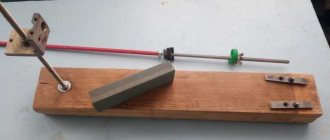
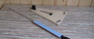
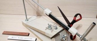
Workplace and additional tools
A wooden table is suitable for the workplace. If you don’t want to spoil the surface of the table, you can use a wooden plank. Wood absorbs little heat and does not act as a radiator. And if you don’t have such a board, you can purchase a silicone heat-resistant mat. This mat has a convenient area for disassembling electronics, various pockets and places for tools. The mat can be cleaned with regular alcohol after use if there are any stains or traces of solder.
Tweezers and spatulas
Using tweezers, you can move parts when soldering, position and install parts. They are also made from different materials, they can be angular, straight, with fixation, etc.
Optics and microscopes
Magnifiers are not very convenient, so it is much more convenient and practical to use microscopes. It's best to start with a budget option. For example, a simple USB microscope will allow you to evaluate the result of soldering on a computer screen.
Of course, the frame rate does not allow you to work normally under it, but it allows you to examine small details of the board without harm to your eyesight.
Room ventilation and safety rules
The room must have good ventilation. When soldering, you need to keep your distance and not get too close to avoid solder getting on your face. After soldering work, be sure to ventilate the room and wash your hands and face with soap. You should not eat food while soldering, because smoke residues remain on mucous surfaces.
Replacing a capacitor without desoldering it from the board
Repair conditions vary, and changing a capacitor on a multilayer (PC motherboard, for example) printed circuit board is not the same as changing a capacitor in a power supply (single-layer, single-sided printed circuit board). You must be extremely careful and careful. Unfortunately, not everyone was born with a soldering iron in their hands, and repairing (or trying to repair) something is very necessary.
As I already wrote in the first half of the article, most often the cause of breakdowns is capacitors. Therefore, replacing capacitors is the most common type of repair, at least in my case. Specialized workshops have special equipment for these purposes. If you don’t have it, you have to use conventional equipment (flux, solder and soldering iron). In this case, experience helps a lot.
And if there is no experience, then an attempt at repair may well end in failure. Just for such cases, I hasten to share a method for replacing capacitors without desoldering them from the printed circuit board. The method is outwardly rather inaccurate and to some extent more dangerous than the previous one, but for personal use it will do.
The main advantage of this method is that the contact pads of the board will have to be subjected to much less heat. At least twice. Printing on cheap motherboards quite often peels off due to heat. The tracks come off, and fixing this later is quite problematic.
The disadvantage of this method is that you still have to put pressure on the board, which can also lead to negative consequences. Although from my personal experience I have never had to press hard. In this case, there is every chance of soldering to the legs remaining after mechanical removal of the capacitor.
So, replacing a capacitor begins with removing the damaged part from the motherboard.
You need to place your finger on the capacitor and, with light pressure, try to swing it up and down and left and right. If the capacitor swings left and right, then the legs are located along the vertical axis (as in the photo), otherwise along the horizontal axis. You can also determine the position of the legs by the negative marker (a strip on the capacitor body indicating the negative contact).
Next, you should press the capacitor along the axis of its legs, but not sharply, but smoothly, slowly increasing the load. As a result, the leg is separated from the body, then we repeat the procedure for the second leg (press from the opposite side).
Sometimes the leg is pulled out along with the capacitor due to bad solder. In this case, you can slightly widen the resulting hole (I do this with a piece of guitar string) and insert a piece of copper wire there, preferably the same thickness as the leg.
Half the job is done, now we move directly to replacing the capacitor. It is worth noting that the solder does not stick well to the part of the leg that was inside the capacitor body and it is better to bite it off with wire cutters, leaving a small part. Then the legs of the capacitor prepared for replacement and the legs of the old capacitor are treated with solder and soldered. It is most convenient to solder the capacitor by placing it on the board at an angle of 45 degrees. Then you can easily stand him at attention.
The resulting appearance is, of course, unaesthetic, but it works and this method is much simpler and safer than the previous one in terms of heating the board with a soldering iron. Happy renovation!
It is believed that about half of the failures of electronic boards are associated with a malfunction of the capacitor, without replacing which the further functioning of the circuit is impossible.
These parts themselves may vary both in characteristics and dimensions; however, they all have one thing in common - the presence of the main controlled parameter (capacity).
In order to check the capacitor installed in the circuit (including the so-called “electrolytes”), it is necessary to measure its capacitance. The faulty part will have to be removed from the circuit and then soldered on with a new one. Some types of capacitors do not need to be soldered, since they are attached by welding or clamps.
Soldering parts from boards with one soldering iron
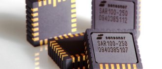
Small-sized SMD parts can be desoldered using a conical tip. Both contacts of the part heat up and it quickly comes off the board. Also, a conical tip is convenient when soldering SMD parts, since you can accurately dose the amount of solder onto the contacts.
Braided soldering
Braid consists of strands of thin copper wires.
You can use shielding insulation from the antenna as a braid. Using a braid, you can quickly and easily remove solder from a contact. It is necessary to apply flux to the braid and contact. Next, using a soldering iron, the soldering area is slowly heated and the tin is transferred to the braid. This soldering method is good for small parts and small DIP contacts. If you need to unsolder the PCI connector, then the braiding will quickly be wasted.
Vacuum syringe and needles
The vacuum syringe quickly removes massive burnt parts of solder. And with the help of DIP needles, the contacts are easily unsoldered from the board. The needle is put on the contact and heated up using a soldering iron. You need to have time to pass the needle through the board contact onto the microcircuit body while the solder is in a molten state. Or vice versa, when the contact is already warmed up, and at the same second the needle is inserted.
Such soldering methods are outdated. Modern boards are manufactured for machine assembly, so the gap between the contacts and pins of the parts is minimal. The needle is already weak, and the vacuum syringe does not have time to pick up the sharp drops of solder. It is no longer possible to desolder a regular electrolytic capacitor using a syringe. In this case, the liquid sting method will help.
Liquid sting and its advantages
The liquid tip is a drop of solder, which allows you to avoid using additional tools (braid, hair dryer, needles or syringe). The technique is the same as with the Rose alloy. The main difference is in temperatures.
The hatchet-type sting has a massive longitudinal working surface. It allows you to capture multiple contacts at once.
Apply solder to the tip. A paste-like flux is applied to the chip to be soldered using a syringe.
The part and its contacts are heated with a sting until the tin melts, and the same must be done on the other side.
Using this technique you can also remove DIP contacts.
Capacity check
There are several ways to check electrolytic capacitors (as well as non-electrolytic ones) to ensure they maintain their nominal capacity (capacity).
But first you need to familiarize yourself with measuring instruments that allow you to correctly estimate the capacitance value of a particular element before soldering anything.
To measure capacitors with nominal capacities up to 20 microfarads, a conventional multimeter with the appropriate function may be sufficient. An inexpensive device like DT9802A can be used as such a meter.
To assess the condition of elements with high ratings, you will need a special device such as an “RLC meter”. Using such a device, you can test not only capacitors, but also such common elements as a resistor and inductor.
Checking the capacitor with a digital multimeter:
Often a faulty capacitor swells and is noticeable without the use of any instruments.
A simple, but not very effective method of identifying a malfunction is checking with a conventional ohmmeter, the reading of which can be used to judge the integrity of the dielectric gasket.
This method is usually used when the device does not have a capacitance measurement function. For these purposes, a simple pointer device can be used, switched to resistance measurement mode.
When the ends of the probe touch the legs of a working element, the arrow should deviate slightly and then return to a similar state.
If the readings on the device have changed, and the needle, after the deviation, has stopped at some final resistance value, this means that the capacitor is broken and must be replaced.
Check in board
One of the most common ways to check a capacitor without removing it from the circuit is to connect in parallel another, previously working capacitor with a known rating.
This method allows you to judge the serviceability of the element by the device indicator, which shows the total capacity of two parallel-connected “condensers”. When capacitors are connected in parallel, their capacitances add up.
With this approach, it is possible to do without soldering the capacitor in order to remove it from the circuit in which it is shunted by elements (resistors) connected in parallel.
However, the possibilities of using this method are limited by the permissible voltages operating in a given electronic circuit and on the board of the device under test.
The method is effective only at small potentials comparable to the maximum voltage values for which the electrolytic capacitor is designed.
How to connect capacitors to increase capacity
So, there is a parallel and series connection of capacitors. When connected in parallel, the capacitance of the capacitors is added, that is, combined. Thus, if you need to get one 7 µF capacitor, then you need to connect two, 6.8 µV and 200 nF.
When capacitors are connected in series, the total value is formed, divided by the sum. This means that there is no point in connecting large capacitors with capacitors of smaller capacity in this way. Always, the capacitors that follow each other will be approximately equal in value.
Thus, the capacitance of series-connected capacitors in the circuit does not increase, but the voltage increases significantly. Therefore, series connection of capacitors takes place where you need to get a stable circuit that can withstand high voltages.
Measurement Precautions
For those who decide to independently check the serviceability of the capacitors built into the circuit and then solder them, we recommend adhering to the following rules.
- Be sure to ensure that the circuit is completely de-energized. To do this, use the same multimeter turned on in voltage measurement mode to check that it is absent at all control points on the board.
- When measuring “suspicious” capacitors built into a circuit, you should be careful not to accidentally damage the elements connected in parallel to it.
- And finally, additionally mounted elements in the circuit must be soldered with extreme caution so as not to damage the rest of the circuit.
Only if all these conditions are met is it possible to keep the controlled device in working condition.
How to resolder a capacitor on the motherboard
Before soldering a new capacitor, you need to unsolder the old one. You should unsolder a damaged or faulty element from the motherboard as quickly as possible, so as not to overheat the contact pads, which otherwise may simply fall off.
To free the legs of the soldered element from solder, you should warm up the seat well. Only if it is sufficiently warmed up when soldering the capacitor is it possible to avoid damaging the board tracks.
When holding a small capacitor on one side, you need to try not to get burned, since its contact becomes hot when heated by a soldering iron.
In addition, you need to be as careful as possible and not use too much force, as the soldering iron tip can break off and damage adjacent parts.
The sequence of actions is as follows:
- First, turn off the power to the computer, disconnect not only the network cable, but also other power wires.
- Remove the cover and unscrew the motherboard.
- They inspect the board and find a damaged element, study its parameters (on the markings), and buy a replacement.
- Note what polarity the capacitor was connected to (you can take a photo).
- Using a soldering station or a soldering iron, the damaged capacitor is soldered out.
- Install and solder a new one.
After removing the capacitor, there remains a free space, which should first be carefully cleaned of solder residues using a suction.
Some radio amateurs use a sharpened match (toothpick) for this purpose, through which the mounting hole is pierced while simultaneously heating with the tip of the soldering iron tip.
Another way to free holes from solder residue involves drilling it out with a drill of a suitable size.
Upon completion of the preparation of the site for the new element, its legs should first be molded accordingly so that they easily fit into the mounting sockets. All that remains to be done after this is to solder it in place of the burnt one.
How to solder with a hairdryer correctly
It is necessary to cover all small components that are vulnerable to overheating with protection.
In this case, aluminum tape is used. It protects components well from temperature and holds the board components tightly. However, it adds heat capacity to the soldering area. Thermal tape also protects well, but sticks to the board less well.
The board is placed on a material that has the least heat capacity and slowly releases temperature to the environment. You can use, for example, a wooden plank. And at the same time, the soldering area should not be inclined.
It is best to apply flux to the contacts. It distributes heat well compared to heated air, but you should not add too much of it. It may boil, hiss, or interfere with soldering.
The first step is to warm up the soldering area. The hair dryer is set to about 100 °C and maximum air flow.
It is necessary to warm up both the part itself and the surrounding soldering area with contacts in a circular motion.
Next, after about a minute, you should gradually increase the heating.
The difference with the contacts will be small. Thus, within a few minutes, increase to 300 °C.
Steps of about 20 - 30 °C for every tens of seconds.
Soldering process
Before soldering, you need to insert the legs into the socket, observing the polarity. The negative leg of the part is usually shorter than the positive leg; it is installed on the “minus” pad (usually painted white). Soldering must be done from the reverse side; to do this, the board is turned over and the legs are bent.
Soldering the capacitor will be much easier if you first moisten the contact “spots” with a drop of flux.
The soldering iron is heated, brought to the contact pad, and the solder wire is brought to it. Use a sting to touch the solder so that a droplet slides onto the soldering site. So you need to solder all the contacts sequentially, and then bite off the extra protruding legs with pliers.
You may not be able to solder beautifully the first time, and you will need to practice. It is better to learn soldering methods in advance on unnecessary parts. After replacing the faulty element, you should try to turn on the motherboard and check its functionality.
The subtleties of good soldering
To solder a part to the board, you need:
1) Apply flux to the soldering surface; 2) Tin them with solder; 3) Apply flux to the contacts again; 4) Solder the gap between the contacts.
The first important rule is to avoid temperatures above 400°C or more. Many beginner (and even experienced) radio amateurs neglect this. These are critical values for microcircuits and boards.
Solder melts at approximately 180 to 230°C (lead-containing solders) or 180 to 250°C (lead-free). This is far from 400 °C. Why then set the temperature high?
What you need for reliable contact
Main criteria:
- Choose the right flux. For example, liquid flux is suitable for soldering wires. It wets wires best and allows for better tinning of such contacts. Low-quality flux quickly boils and spreads over the board.
- Use high quality solder. It is the solder that determines the further reliability and strength of the connection. Also, the quality of the solder can affect the operation of the circuit as a whole; due to slag and low-quality alloys, interference may occur in the operation of the electronics and, over time, cracks may appear.
- Use proven tools and equipment. Soldering irons of poor quality can maintain temperature unstably and overheat.
- Maintain temperature conditions. Do not overheat the parts and stay within the melting temperature of the solder. The temperature is too low and the solder will not melt well, and if it is too high, the material will evaporate, making it worse to tin the contacts.
- Long hours of practice, trial and error. Without practice, there will be no soldering method.
These criteria are interrelated with each other. And with a poor choice of components and materials, the same result will occur.