When to connect cables
Cable connections will be required in case of poor-quality wiring performed earlier, or due to errors made during installation work. To restore power to the house, you need to connect the electrical wires. You can make a connection in ways that are divided into 2 groups:
- For the first group, no special equipment is required.
- The second group already requires certain skills and professional tools.
Work on connecting cables must be carried out in compliance with safety regulations.
Types of cables for connection
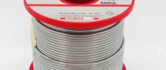
The most common cable for home electrical wiring is a PVA connecting cable, consisting of two insulating layers.
Copper strands, stranded, twisted along the central axis. The wire is flexible, making it great for a variety of connections. The voltage of connected devices must be up to 380 Volts.
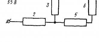
The cross section is selected depending on the load:
- for a current of 6 A, PVA with a cross section of 0.75 mm is used;
- for 10 Amperes - the cross-section is 1 mm;
- for currents of 16 A – 1.5 mm.
In addition to the PVS wire, for connection there are multi-core cables ShVVP, PUGNP, PRS, KG. They are used less frequently for home wiring than PVS.
What is the best way to reliably connect two cables together?
Methods of connecting cables that require equipment and skills in the field of electrical engineering:
- soldering;
- welding;
- crimping with sleeves.
Simple connection methods that do not require tools or knowledge:
- connection using terminal blocks;
- spring clamps;
- PPE caps;
- bolted connection.
The choice of connection method depends on the characteristics of the wires. It is necessary to take into account the type and material of the core, the number of wires, and operating conditions.
With soldering
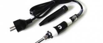
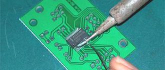
Soldering is a common method of connecting cables. To work you need a soldering iron, rosin, solder and sandpaper. How to connect wires by soldering:
- stripping of insulation;
- cleaning from oxides using sandpaper;
- the conductors need to be tinned - rosin is placed on the wire, it is heated with a soldering iron until the wire is covered with rosin;
- the conductors are assembled together, bubbling rosin must be applied to them and heated until the solder spreads;
- The soldering area is cooled.
The complexity of the process lies in the availability of professional skills. Do not overheat the solder area or twist it when heating, otherwise the insulation may melt. It is important to ensure high-quality and reliable contact of the wires. Soldering is used in low-current electrical applications.
No soldering
Wires are connected without soldering using special connecting elements. It is also possible to connect the wires by twisting. Twisting is the simplest method that does not require equipment, but this method is also the most unreliable.
It is prohibited to use only a twisted connection according to the rules of the PUE.
Copper
Copper wire can be connected using terminal blocks, Wago clamps (necessarily using special paste), using a bolt, or soldering.
Aluminum
Aluminum wires can also be connected using any method, but with some special features. When connecting, the metal must be manually stripped of insulation.
Copper and aluminum wires cannot be connected directly. The connection point becomes very hot and over time the contact weakens. Therefore, it is better to use terminal blocks, wago, bolt connection or special branch clamps.
Welding – high reliability in any conditions
When connecting wires by welding, the conductors are twisted and their ends are welded. As a result, a metal ball is formed, which provides a stable and very reliable connection in any conditions. Moreover, it is reliable not only in terms of electrical characteristics, but also mechanically - the metal of the connected wires after melting forms a monolith and it is impossible to isolate a separate conductor.
Welding - it is important to heat the metal, but not melt the insulation
Yandex.RTB RA-1479455-7
The disadvantage of this type of wire connection is that the connection is 100% permanent. If you need to change something, you need to cut off the fused piece and do it all over again. Therefore, for such connections, a certain supply of wires is left in case of possible alterations.
Other disadvantages include the need for a welding machine, appropriate electrodes, flux and operating skills. In addition, welding takes a lot of time, it is necessary to protect surrounding objects, and it is also inconvenient to work with a welder at height. Therefore, electricians practice this type of connection in exceptional cases. If you are doing it “for yourself” and know how to handle a welding machine well, you can practice on scraps. The main trick is to not melt the insulation, but to weld the metal.
After cooling, the welding site is isolated. You can use electrical tape, you can use heat shrink tubing.
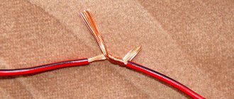
Is it possible to connect cables by twisting?
According to the rules of the PUE, twisting is prohibited, as it does not provide reliable contact. It can only be used in conjunction with another connection method. It is also unacceptable to use twisting to join two different metals.
Stranded and single-core
When connecting multi-core wires, the following rules should be followed:
- strip the insulation by 4 cm;
- unwind the conductors by 2 cm;
- connect to the junction of untwisted conductors;
- twist the wires only with your fingers;
- You can tighten the twist using pliers;
- bare wires are insulated with special tape or heat shrink tubing.
Twisting solid wires is much easier. They need to be stripped of insulation, twisted by hand along the entire length, then clamped with pliers and insulated.
Twisting methods
You can do twisting in different ways. It can be made by branch, parallel or series connection. Also, to improve the reliability of contact, caps and clamps are additionally used.
Correct twisting of electrical wiring in a junction box
When twisting, you need to follow the following procedure:
- cut off power to a house or apartment;
- clear the wiring of 4 cm or more of insulation;
- unwind the wires by 2 cm;
- connect untwisted wires to the junction;
- twist the veins with your fingers;
- tighten the twist with pliers;
- insulate exposed wires.
Both single-core and multi-core cables can be connected.
Twisting of different sections
Do not twist wires with very different diameters. Such contact is not reliable and stable. You can twist wires of adjacent sections - for example, 4 sq. mm and 2.5 sq. mm. When twisting, you need to make sure that both wires wrap around each other. A thin wire should not be wound onto a thick one, otherwise the contact will be unreliable. Then you need to solder or weld the joint.
Twist caps
The caps help to reliably insulate the contact point.
The cap is made of fire-resistant material, inside it there is a metal part with threads. Making twists using caps is quite simple - you need to remove 2 cm of insulation and lightly twist the wires. A cap is put on them and turned several times until the metal wires are inside.
With terminal clamps
The contact clamp consists of a screw, a spring washer, a base, a current-carrying core and a stop that limits the spreading of the aluminum conductor. Making a connection using a contact clamp is simple - just strip the ends of the wires by 12 mm and insert them into the hole in the clamp. Contact clamps are used for both solid and stranded conductors.
How to brew twist
After twisting, the wires need to be soldered. To do this, the wires are tinned and rosin is applied to them before twisting. The heated soldering iron is lowered into the rosin; it needs to be passed along the stripped part of the wiring. After twisting, take tin on a soldering iron and heat the joint until tin begins to flow between the turns. This method takes a lot of time, but it is reliable and of high quality.
Basic wiring diagrams
Knowing how to connect the wires in the junction box is not everything. You need to figure out which wires to connect.
How to connect sockets
As a rule, the socket group runs on a separate line. In this case, everything is clear: you have three cables in the box, each with three (or two) conductors. The color may be the same as in the photo. In this case, usually brown is the phase wire, blue is neutral (neutral), and yellow-green is ground.
Wiring diagram for a socket in a distribution box
In another standard, the colors may be red, black and blue. In this case, the phase is red, blue is neutral, green is ground. In any case, the wires are collected by color: all of the same color in one group.
Then they are folded, stretched, and trimmed so that they are the same length. Do not cut short, leave a margin of at least 10 cm so that if necessary you can re-seal the connection. Then the conductors are connected using the chosen method.
If only two wires are used (in houses of old construction there is no grounding), everything is exactly the same, only there are two connections: phase and neutral. By the way, if the wires are the same color, first find the phase (with a probe or multimeter) and mark it, at least by wrapping a piece of electrical tape around the insulation.
Connecting a single-key switch
If there is a switch, the matter is more complicated. There are also three groups, but their connection is different. Eat
- input - from another junction box or from a panel;
- from the chandelier;
- from the switch.
How should the circuit work? Power - “phase” - goes to the switch key. From its output it is fed to the chandelier. In this case, the chandelier will light only when the switch contacts are closed (the “on” position). This type of connection is shown in the photo below.
Methods for connecting wires or cables to each other
The junction of two conductors must meet the following requirements:
- reliability;
- mechanical strength.
These conditions can also be met when connecting conductors without soldering.
Crimping
This method requires special equipment. Crimping of wires with sleeves is carried out for both copper and aluminum wires of different diameters. Depending on the cross-section and material, the sleeve is selected.
Crimping algorithm:
- stripping of insulation;
- stripping wires to bare metal;
- the wires need to be twisted and inserted into the sleeve;
- the conductors are crimped using special pliers.
Selection of a sleeve causes major difficulties. An incorrectly selected diameter will not ensure reliable contact.
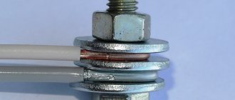
Bolted connection
Bolts, nuts and several washers are used for contact.
The connection point turns out to be reliable, but the structure itself takes up a lot of space and is inconvenient to install. The connection order is as follows:
- stripping of insulation;
- the stripped part is laid in the form of a loop with a diameter equal to the cross-section of the bolt;
- a washer is put on the bolt, then one of the conductors, another washer, a second conductor and a third washer;
- the structure is tightened with a nut.
Using a bolt, you can connect several wires. The nut is tightened not only by hand, but also by a wrench.
Terminal blocks
The terminal block is a contact plate in a polymer or carbolite housing. With their help, any user can connect wires. The connection occurs in several stages:
- stripping the insulation by 5-7 mm;
- removal of oxide film;
- installing conductors in sockets opposite each other;
- fixation with bolts.
Pros - you can connect cables of different diameters. Disadvantages - you can only connect 2 wires.
Types of terminal blocks for multi-core and single-core cables
There are 5 main types of terminal blocks:
- knife and pin;
- screw;
- clamping and self-clamping;
- cap-shaped;
- "walnut" type clamps.
The first type is rarely used; they are not designed for high currents and have an open design. Screw terminals provide reliable contact but are not suitable for connecting multi-core cables. Clamp terminal blocks are the most convenient devices to use; their installation does not require special equipment. Cap-type devices are also often used, but unlike clamping devices, caps can be used repeatedly. "Nut" is practically not used.
Terminals in junction box (copper or metal)
Terminals are the most common connection method in a junction box. They are cheap, easy to install, provide reliable contact fixation and can be used to connect copper and aluminum. Flaws:
- cheap devices are of low quality;
- Only 2 wires can be connected;
- Not suitable for stranded wires.
Self-clamping terminal blocks WAGO
There are 2 types of Vago terminal blocks used:
- With a flat spring mechanism - they are also called disposable, since reuse is impossible. Inside there is a plate with spring petals. When installing the conductor, the petal is pressed out and the wire is clamped.
- With lever mechanism. This is the best connector option. The stripped conductor is inserted into the terminal and the lever is clamped. Re-installation is possible.
With proper use, Vago terminal blocks last 25-30 years.
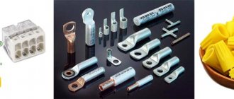
Using Tips
For connection, 2 types of tips and sleeves are used:
- in the first, the connection is made inside the product;
- in the second, two electrical wires are terminated with different tips.
The connection inside the sleeve or tip is strong and reliable. There are also special sleeves for connecting copper and aluminum wires.
Soldering of electrical wiring lugs
The tips are connected to the wiring using a press.
If it is not there, contact can be ensured by soldering. The electrical wire and the tip inside are tinned, the stripped cable is inserted inside.
The entire structure on the contact must be wrapped with fiberglass tape and heated with a burner until the tin melts.
Why do you need a junction box?
Electrical wires, starting from the distribution panel, are carried through all rooms of the house or apartment. In each room, these wires are connected either to sockets or to lighting, which operates on the basis of electrical switches as well as lighting fixtures. The wires that are brought into a separate room first of all end up in a distribution box, and then go to their intended purpose - some wires connect sockets, and other wires connect lighting. It is in the distribution box that these wires are connected so that the electrical system works correctly - sockets and lighting must function independently of each other.
Electrical wiring rules
Electrical wires are routed throughout the premises so that they can be easily found in case of emergencies, and for this purpose rules are prescribed, 4 which are included in a separate section called “Rules for Electrical Installations” or abbreviated as “PUE”.
The PUE says that all connections and branches of wires are made in the junction box. The wiring is carried out at a distance of 15 cm from the ceiling level, after which, if it is necessary to make a branch, the wires are lowered at a right angle. At the branch points, distribution boxes are installed in which the wires are connected according to the connection diagram.
Some forms of junction boxes
There are distribution boxes for surface and also for hidden installation of electrical wiring. Hidden installation involves the formation of recesses at installation sites into which distribution boxes are installed so that the covers are flush with the wall. As a rule, distribution boxes are covered with finishing material (for example, covered with wallpaper) so that they do not spoil the appearance of the interior. If you know the wiring diagram, then finding a junction box if something happens is not so difficult. In some cases, which is rare these days, surface mounting is carried out. In this case, distribution boxes, like sockets, like switches, are installed directly on the wall (or on another base).
Distribution boxes are produced either round, which is much more common, or square. There are usually four terminals for connecting wires, but there may be more. The conclusions are made so that it is possible to connect wires placed in corrugated hoses or plastic pipes. This approach allows you to quickly replace wires in case of emergency conditions. Often, electrical wires are routed in grooves - peculiar recesses made in the walls. On the one hand, it’s simple, but on the other hand, if the wires are damaged, replacing them is very difficult. In any case, it is better to do everything as required by the PUE.
The use of distribution boxes allows you to:
- Increase the maintainability of electrical networks. Since all connections are accessible, the nature of the problem can be easily determined and the problem can be quickly resolved.
- Connection locations present the greatest potential for malfunctions. Easy access to connections allows for regular inspection.
- Reduce the level of fire safety, since constant inspection allows for a timely response to emergency operating conditions.
- Reduce the cost of purchasing electrical wires or cables. Electrical wiring made without junction boxes requires a lot of materials.
Connectors for wires and cables
Connectors are special devices that facilitate the connection of two or more conductors. There are screw and clamping mechanisms.
Screw terminals
Used to connect wires of different materials and different diameters. An exception is multi-core electrical wires, which are crimped with special lugs. Also, screw clamps can damage aluminum wires, so it is better not to use them for such material.
Screw terminals
Allows you to connect aluminum and copper conductors together. They are easy to connect.
Power clamp
In such clamps, the stripped conductor is placed in the hole to the end. There it is automatically fixed by a pressure plate. Clamps can be used to secure copper and aluminum wires.
Clips
To install the wire, the clip clamp is placed in a vertical position, the wires are inserted inside, and then the clamp must be moved to a horizontal position. Plus, you can make adjustments.
Spring clamps
PPE caps are used as spring clips. Thanks to them, you can quickly make contact between two wires of similar diameters. It is important to choose the correct clamp, otherwise the contact will be unreliable.
Spring terminals
Wago spring terminals ensure reliable contact quickly and efficiently. However, over time, the spring may weaken or overheat.
Connection clamps
There are two types - electrical and electrical. The only difference is the current load. The connection takes place inside the device.
Couplings
It is made in the form of a metal tube. Used for conductors with a cross section of 0.25-16 mm. The wire is fixed by force crimping. Not used for single-core wires.
Terminals
Terminal blocks for connecting wires provide one undeniable advantage: they can connect cores of different metals. Both here and in other articles, we have repeatedly reminded that twisting aluminum and copper wires together is prohibited. The resulting galvanic couple will result in corrosion processes and destruction of the connection. And it doesn’t matter how much current flows at the connection. Late or early, the twist will still start to heat up. Terminals are the way out of this situation.
Terminal block
The simplest and cheapest solution is polyethylene terminal blocks. They are not very expensive and are sold in every electrical goods store.
The polyethylene frame is designed for several cells, inside each there is a brass tube (sleeve). The ends of the connected wires must be inserted into this sleeve and clamped with two screws. It is very convenient that as many cells are cut from the block as it is necessary to connect pairs of wires, for example, in one junction box.
But not everything is so smooth, there are also disadvantages. At room conditions, aluminum begins to flow under screw pressure. You will have to periodically inspect the terminal blocks and tighten the contacts where the aluminum conductors are fixed. If this is not done in a timely manner, the aluminum core in the terminal block will become loose, lose reliable contact, and, as a result, spark and heat up, which can result in a fire. Such problems do not arise with copper conductors, but it would not be superfluous to periodically inspect their contacts.
Terminal blocks are not intended for connecting stranded wires. If stranded wires are clamped into such connecting terminals, then when tightening the screw under pressure, the thin wires may partially break, which will lead to overheating.
In cases where it becomes necessary to clamp stranded wires into a terminal block, it is imperative to use auxiliary pin lugs. It is very important to choose the correct diameter so that the wire does not jump out later. The stranded wire must be inserted into the lug, crimped using pliers and secured in the terminal block.
As a result of all of the above, the terminal block is an ideal option for single-core copper wires. With aluminum and stranded ones you will have to comply with a number of additional measures and requirements.
How to use terminal blocks is shown in this video:
Terminals on plastic blocks
Another very convenient wire connector is a terminal on plastic blocks. This option differs from terminal blocks in that it has a smooth metal clamp. The clamping surface has a recess for the wire, so there is no pressure on the wire from the screw being tightened. Therefore, such terminals are suitable for connecting any wires.
Everything about these clamps is extremely simple. The ends of the wires are stripped and placed between the contact and pressure plates.
Such terminals are additionally equipped with a transparent plastic cover, which can be removed if necessary.
Self-clamping terminals
Wiring installation using such terminals is simple and quick.
The wire must be inserted into the hole to the very end. There it is automatically fixed using a pressure plate, which presses the wire to the tinned busbar. Thanks to the material from which the pressure plate is made, the clamping force does not weaken and is maintained all the time.
The internal tinned busbar is made in the form of a copper plate. Both copper and aluminum wires can be fixed in self-clamping terminals. These terminals are disposable.
And if you want clamps for connecting reusable wires, then use terminal blocks with levers. They lifted the lever and inserted the wire into the hole, then fixed it there by pressing it back. If necessary, the lever rises again and the wire protrudes.
Try to choose clamps from a manufacturer that has proven itself well. The clamps have especially positive characteristics and reviews.
The advantages and disadvantages are described in this video:
PPE caps – connecting insulating clips
Now let’s look at the PPE spring caps in detail. These clamps have not gained such great popularity among electricians and ordinary people, and there are reasons for this.
Terminal clamp
This device will not be a block, but depending on the model, it can connect up to 8 conductors in one housing.
The outer material is plastic, which has a number of features:
- Does not support combustion even when exposed to open fire;
- Has a high melting point;
- Withstands voltages from 300 to 600 V, which indicates high insulating properties;
- It has high mechanical strength and reliably protects the connection from any damage.
The cap has a cone shape. The outside is corrugated or has two blades for ease of use.
A compression spring of the same shape is installed inside. As was written above, its edges are sharpened in a special way, which allows you to securely fix cores of different sizes.
If we compare PPE with Vago terminals, they will have a couple of obvious disadvantages:
- Inability to simultaneously connect aluminum and copper wires.
- Complicated installation that requires special processing of the wires - it is necessary to thoroughly clean the insulation without protruding even a millimeter of the bare part of the wire beyond the cap body.
- An accurate selection of the cap model for the wire cross-section is required, since the best contact will be in the narrowest place, and if the wires are too thin, there will be increased resistance at the connection point, as when twisting the wires.
- Sufficient force is required to ensure good contact between the conductors.
- The cores must be strictly the same diameter.
- For multi-core wires, this solution will not be the best, since partial damage to thin wires is possible.
PPE caps in the junction box
The cap is installed in the following sequence:
- The wires are exposed from insulation to a length corresponding to the length of the corrugation on the cap;
- Their ends are connected in parallel, without preliminary twisting.
- The cap is placed on top and rotated with force clockwise.
- When connecting three wires, a preliminary twist is made, after which its tip is bitten off.
How PPE works
The following video will show how to install PPE caps.
There are five types of PPE terminals in total, the difference between which can be seen in the following image.
The difference between PPE caps
Interesting to know! PPE 5 can be used to connect 8 cores with a cross section of 2.5 mm2.
The table also shows the color coding of the models. The majority of manufacturers adhere to it, but there is no single standard, so there may be differences, so be careful when purchasing.
Pay attention to the product labeling (PPE 1 1.0-3.0 and similar). It will help you accurately select the product for the cross-section of your wire.
The first digit of the marking indicates the type of housing, the rest indicate the permissible range of cross-sections.
Safety Tips and Rules
Only craftsmen with a qualification group are allowed to weld.
Persons who have skills in working with a soldering iron are also allowed to solder. Cables may only be connected in the manner permitted for them. Do not work with damaged wiring. All exposed parts must be insulated.
You can connect the cables in different ways. The choice of connection method is determined by the material, cross-section diameter and other parameters. For electrical equipment to operate correctly, the conductors need to be connected securely. In case of unreliable contact, there is a risk of fire.