We recommend purchasing:
Installations for automatic welding of longitudinal seams of shells - in stock!
High performance, convenience, ease of operation and reliability in operation.
Welding screens and protective curtains are in stock!
Radiation protection when welding and cutting. Big choice. Delivery throughout Russia!
Slot milling
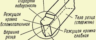
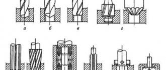
A recess of metal in a part, limited by shaped or flat surfaces, is called a groove. Grooves can be rectangular, T-shaped, dovetail, shaped, through, open, closed, etc. Processing grooves is a common operation on milling machines of various types and is carried out with disk, end and shaped cutters (Fig. 5.23).
Through rectangular grooves are most often milled with three-sided disk cutters (Fig. 5.23, a), disk groove or end mills (Fig. 5.23, b). When milling precise slots, the width of the disk cutter (diameter of the end mill) must be less than the width of the slot, and milling to a given size is carried out in several passes. Machining grooves with end mills requires the correct choice of the direction of rotation of the machine spindle relative to the helical grooves of the cutters. It should be mutually opposite.
Milling of closed grooves is carried out on vertical milling machines using end mills (Fig. 5.23, d). The diameter of the cutters should be 1...2 mm less than the width of the groove. Plunging to a given cutting depth is carried out by moving the table with the workpiece in the longitudinal and vertical directions, then the longitudinal movement of the table feed is turned on and the groove is milled to the required length, followed by finishing passes along the sides of the groove.
Curvilinear grooves are milled to their full depth in one working stroke. According to this condition, the resulting feed motion is assigned, equal to the sum of the vectors of the transverse and longitudinal feed motion. To reduce infeeding in places where the directions of the grooves change, it is necessary to process with cutters with minimal overhangs and reduce feed rates.
Milling of grooves of special profiles - T-shaped, dovetail-type - is carried out on vertical or longitudinal milling machines in three (T-shaped grooves) or two (dovetail-type grooves) transitions. Taking into account the unfavorable operating conditions of T-shaped and single-angle cutters used in these operations, the feed per tooth S should not exceed 0.03 mm/tooth; cutting speed - 20...25 m/min.
Key and key connection
A keyed connection is a type of connection consisting of a key on the shaft and a hub. A key is a part that connects nodes by installing them in grooves. Its main function is to transmit torque between nodes. There is a certain standardization of their varieties. The key has special grooves cut by milling.
Application
The main application of keyed connections is mounting on a shaft using a grooved connection. In most cases, the keyway resembles a wedge. This type of connection of parts allows the shaft and hub not to rotate relative to each other’s axis. The fixed position of the hub to the shaft with a key allows for high efficiency when transmitting force.
Most often, keyed connections can be found in mechanical engineering, during the construction of machine tools. It is often used in the production of cars and other mechanisms, where increased reliability of fixing machine parts is required. High reliability is achieved thanks to the function of the shaft safety unit with keyway.
The key acts as a fuse in cases where the maximum torque level is exceeded. In such cases, the key is sheared, absorbing the excessive load and removing it from the shaft and hub.
Due to its properties, it has become widespread in mechanical engineering; it is characterized by high efficiency, ease of manufacture and installation, and low cost. Such characteristics are especially important in industrial production, especially in agriculture. At the height of the season, there are often cases of breakdowns of individual components that need to be replaced as quickly as possible. Most often found in baler units.
Considering all of the above, the main positions for which a key is needed are highlighted:
In general, you can find a keyed connection in almost any complex mechanism, which is due to its technical characteristics.
Types of keys
The main types of keys are divided into two types: stressed and unstressed. Among which are the following types of keys:
Based on the type of landing, the following are distinguished:
Designations on the drawings
In the drawings, the designation of parallel keys is based on the GOST regulatory document. They are divided into keyways: high, normal height and guides. Their working faces are the lateral ones.
In the assembly drawing, the designation is made taking into account the shaft diameter, torque, cross-section and length.
Key 3–20Х12Х120 GOST 23360-78; Where 3 is the design, 20X12 is the section, 120 is the length.
Download GOST 23360-78
The designation of other types of keys in the images is carried out in the same way, based on the corresponding GOSTs developed for each individual model. The specified designation must clearly characterize the part, which is very important for obtaining a reliable connection. After all, even the slightest gap can cause rapid wear of working units and loss of efficiency during operation.
Advantages and disadvantages
Like any type of connection, keyed connections have a number of advantages and disadvantages. The advantages of keyed connections include the simplicity of most types of keys. At the same time, installation and replacement of such a part is easy and quick. Thanks to this, they are widely used in mechanical engineering. Also provides protection function.
Disadvantages include weakening of the hub and shaft. It arises from increased stress and reduced cross-section. Also, the weakening of parts is caused by the cut groove, which reduces the axial strength of the shaft.
To minimize the shortcomings, you need to ensure that the key is not skewed in the groove. To do this, you need to ensure that there is no gap, which is done by individually manufacturing and adjusting the key. Because of this, any type of keyed joints are rarely used in large-scale production. If it is not possible to ensure the absence of misalignment, the working contact area decreases, as a result of which the degree of maximum load decreases.
Also, the presence of a gap causes a runout effect, especially at high speeds. This will lead to rapid wear of working parts. Because of this, such a connection is rarely used for rapidly rotating shafts. To select a suitable key, it is better to use the table of key connections.
For the manufacture of keyed joints, calibrated rolled metal is used. The most commonly used steel is grade 45. It is a regular type of carbon steel, which is often used to produce high-strength parts. The steel is used in the form of a 1 m long bar.
In some cases, carbon steel grade 50 can be used. It is necessary when increased strength properties of the resulting keys are required. Less commonly used are alloy steels, for example, grade 40x, which is characterized by a high hardness index achieved by heat treatment.
Download GOST 8787-68
Steel blanks are processed using cutters, drilling machines, chopping machines, grinders and other tools. The machines used have a control unit that allows, using numerical programs, to produce a part with the required parameters.
The price of the resulting key is quite low, so purchasing the necessary part is quite easy. But in some cases, when there is an urgent need to obtain a key, you can make it yourself. Most often, such a need arises in agriculture, where during seasonal work breakdowns often occur that need to be repaired. At the same time, the nearest points of sale of the necessary parts are located at a distance of several tens of kilometers.
With a small amount of tools on hand and a blank made of the appropriate material, you can quickly make a temporary replacement. If the technical specifications are observed, the resulting part can fully replace the factory one, but it is best to purchase a key of the required strength and geometric parameters at the first opportunity. This is necessary to avoid premature wear of the mechanisms.
Sometimes other materials, such as high quality plastic, may be used for production. Wood can be used as a material, most often in the manufacture of furniture.
It is better to use different types of wood as a material; for a dowel, a softer material than the main one is suitable. This will protect the main structure from damage in case of increased load. It is easier to replace a key than a large structural unit.
To prevent moisture from penetrating into reinforced concrete structures, special dowels called waterstop are used. They are made from high quality rubber and PVC. This allows you to achieve the required degree of waterproofness and resistance to solutions of aggressive chemicals.
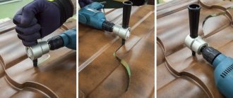
Features of keyway milling
Keyways on shafts are divided into through, open, closed and semi-closed. They can be prismatic, segmental, wedge, etc. (corresponding to the sections of the keys). It is convenient to fix the shaft blanks on the machine table in prisms. For short workpieces, one prism is sufficient. For long shaft lengths, the workpiece is mounted on two prisms. The correct location of the prism on the machine table is ensured with the help of a tenon at the base of the prism, which fits into the groove of the table (Fig. 5.24).
Keyways are milled with slotted disk cutters, backed slotted cutters (GOST 8543-71), keyed cutters (GOST 9140-78) and mounted cutters. The slot or key cutter must be installed in the diametral plane of the workpiece.
Milling of open keyways with a groove exiting along a circle, the radius of which is equal to the radius of the cutter, is carried out using disk cutters. Grooves in which the groove is not allowed to exit along the radius of the circle are milled with end or key cutters.
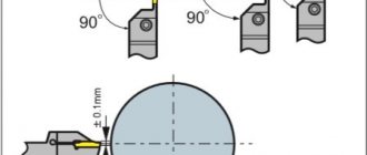
Sockets for segment keys are milled with shank and attachment cutters on horizontal and vertical milling machines. The direction of feed movement is only towards the center of the shaft (Fig. 5.25, a).
To obtain grooves that are precise in width, processing is carried out on special key-milling machines with pendulum feed (Fig. 5.25, b). With this method, the cutter cuts 0.2...0.4 mm and mills the groove along the entire length, then again cuts to the same depth and mills the groove along the entire length, but in a different direction.
For milling keyways, it is recommended to use keyway cutters with S_= 0.02…0.04 mm/tooth at a cutting speed v = 15… 20 m/min; disc slot cutters with S_ = 0.03… 0.06 mm/tooth at cutting speed v = 25…40 m/min.
An operation similar to slot milling is groove milling
on blanks of cutting tools. The grooves can be located on the cylindrical, conical or end part of the workpieces. Single-angle or double-angle cutters are used as a tool for grooving.
When milling angular grooves on the cylindrical part of a cutting tool with a rake angle γ = 0° using single-angle cutters, the tops of the cutter teeth must pass through the diametrical plane of the workpiece. The cutter is installed using a square (Fig. 5.26, a) in the center of the spindle inserted into the conical hole so that the tops of the teeth of the cutters and the center are aligned, and then the workpiece is moved in the transverse direction by an amount equal to half its diameter, or along the line drawn at the end or the cylindrical surface of the workpiece, passing through its center plane (Fig. 5.26, b).
When processing corner grooves with a given positive value of the rake angle γ, the end surface of a single-angle cutter must be located from the center plane at a certain distance x (Fig. 5.26, c), which can be determined by the formula
x=D/(2sinγ),
where D is the diameter of the workpiece, mm; γ—rake angle,°.
When setting up the processing of angular grooves, the tops of the teeth of a double-angle cutter should be set in the diametrical plane using one of the methods discussed above, and then the workpiece should be shifted relative to the cutter by an amount x (Fig. 5.26, d), which depends on the workpiece diameter D, profile depth groove h, working cutter angle 8 and cutter rake angle γ:
x = D/(2sin(γ+δ) - hsinδ/cosγ).
At γ= 0° x = (D/2 - /0)sinδ.
The workpiece can be installed and secured in one of the following ways: at the centers of the index head and tailstock, or at the centers on the mandrel.
Angle cutters are also used when milling angular grooves on a tapered surface. The cutters are installed relative to the diametrical plane of the workpiece in the same way as when milling angular grooves on a cylindrical surface.
When milling angular grooves on a conical surface, the workpiece can be secured in a three-jaw chuck, on an end mandrel inserted into the tapered hole of the index head spindle or into the centers of the index head and tailstock. The last of the listed methods for installing the workpiece is used with a small taper angle.
Processing grooves and ledges
We continue to publish materials from the Milling Machine Operator's Handbook edited by V.F. Tongueless. This time we will analyze the processing of grooves and ledges on processing milling machines.
A ledge is a recess limited by two mutually perpendicular planes forming a step. The part may have one, two or more ledges (Fig. 5.11). Depending on the shape of the recess, the grooves are divided into rectangular, T-shaped and shaped (Fig. 5.11, a–e). Grooves of any profile can be through, open or closed.
Rice. 5.11. Grooves and ledges: a–e – shapes of grooves; e – part with a groove and a ledge
Milled shoulders and grooves are subject to different technical requirements depending on the purpose of the product, serial production, dimensional accuracy, location and surface roughness. All these requirements determine the processing method. Milling of shoulders and grooves is carried out with disk and end mills, as well as a set of disk cutters. In addition, shoulders can be machined with end mills.
The type and size of the disk cutter are selected depending on the size of the surfaces being machined and the material of the workpiece (Fig. 5.12). Based on this, the type of cutter, the material of the cutting part and the main dimensions are determined - B, D, d and z. For easily processed materials and materials of medium processing difficulty with a large milling depth, cutters with normal and large teeth are used. For difficult-to-cut materials with small cutting depths, it is recommended to use cutters with normal and fine teeth.
Rice. 5.12. Scheme of milling a shoulder with a disk cutter on a horizontal milling machine
The diameter of the cutter should be chosen as small as possible. The smaller the diameter of the cutter, the higher its rigidity and vibration resistance. In addition, as the diameter decreases, the durability of the cutter sometimes increases.
For a given milling depth, it is necessary to ensure a guaranteed gap between the mounting ring on the mandrel and the workpiece. If we take the gap value to be 6...8 mm, then the minimum cutter diameter will be determined by the ratio, mm:
D = 2t + d1 +(12…16),
where d1 is the diameter of the installation ring, mm.
Disc groove cutters mainly machine through and open grooves. The use of these cutters allows you to obtain the most accurate grooves; The width of the groove can be processed using 9…10 grades. Groove cutters have cutting edges only on the cylindrical part; to reduce friction, undercuts at an angle of 2° are provided on the side surfaces of the cutter. As the teeth are ground, the width of the cutter decreases, which leads to a change in the size of the groove. The teeth of these cutters cut chips the size of which is equal to the width of the groove. With a large cutting depth, the chips are packed in the cavity, which sometimes causes breakage of the tooth and the cutter as a whole, so these cutters are used when milling shallow grooves.
The three-sided disc cutter provides higher productivity in groove processing. The presence of side teeth, as well as cutting chips whose size is smaller than the width of the groove, improves cutting conditions, increases the accuracy of the groove dimensions and the quality of its surfaces. However, the disadvantage of these cutters is the reduction in size B (cutter width) after the first sharpening. To eliminate this, width-adjustable cutters are used, which consist of two halves with teeth of alternating direction on the cylindrical part. A ring is placed between the halves, the width of which ensures that size B is obtained.
Shoulders and grooves are machined with end mills on vertical and horizontal milling machines (Fig. 5.13). Mills with normal teeth are used for semi-finishing and finishing milling, and cutters with large teeth are used for roughing. The selection of cutters and determination of their operating parameters is carried out in accordance with existing recommendations.
Rice. 5.13. Scheme of milling a groove with an end mill on a horizontal milling machine equipped with a reading indicator device: 1 and 2 – indicators
When setting up the machine, it is important to install the cutter correctly. When using devices, this is quite simply done according to the settings (Fig. 5.14). The installation position is specified relative to the basic elements of the device with dimensions L. As a rule, the cutter is adjusted using a feeler gauge - a metal plate of a fixed size (1, 3 or 5 mm).
Rice. 5.14. Schemes of orientation of cutters according to installation: a, b – end; c – disk; 1 – charters; 2 – dipstick
To adjust the tool vertically (Fig. 5.14, a), you must manually move the machine console up and use a feeler gauge to check the relative position of the tool and the setting. The tool is considered adjusted to a given size if the feeler gauge passes tightly and without oscillation between the mounting surface and the cutting edge of the cutter tooth. A sharp rise of the console until the cutter tooth touches the surface of the probe is unacceptable, as this can lead to chipping of the cutter tooth and damage to the probe. Sometimes a strip of paper is placed on the probe, and if the paper moves when turning the cutter, then in order to finally adjust it to the given size, the console must be raised another 0.03...0.05 mm.
Adjusting the tool horizontally (Fig. 5.14, b, c) relative to its side surface is also carried out using the feeler gauge, but by moving the table in the transverse direction.
If there is no setting, the position of the cutter can be set differently. If the accuracy requirements are low, the groove can be processed according to the markings. For more precise tolerances, other methods of setting the cutter are recommended. So, if the side surface of the workpiece allows risks, the table with it is brought to the cutter until a faint mark from the rotating cutter appears on the surface. By setting the dial of the transverse feed screw to zero division, the workpiece is moved away from the cutter in the longitudinal direction. Then the table is moved along the limb in the transverse direction to the position required for processing the groove (56 mm in Fig. 5.15, a).
Rice. 5.15. Schemes for setting the cutter relative to the workpiece without installation
To install the cutter, you can use plane-parallel end blocks, which provide high setting accuracy. Square 1 (see Fig. 5.15, b) is pressed against the surface of the fixed workpiece, and a block 3 of tiles (44 mm in size in the figure) is placed in the space between it and cutter 2. When moving a table with a workpiece in a block, periodically check the size of the gap. The installation is considered completed if the block of tiles fits tightly and without movement into the space between the square and the cutter.
The orientation of the cutter relative to the center of the shaft is performed according to the scheme shown in Fig. 5.15, c. Dimension A between the square and the cutter must be the same on one side of the shaft and on the other. This is determined using a square and a set of tiles or using a universal measuring tool.
When processing a batch of workpieces, the adjustment process can be facilitated by using a device with two indicators, which allows you to quickly and accurately set the table with the workpiece to the required position after it has been displaced in the transverse and vertical directions. When the machine is configured, indicators 1 and 2 of the device (see Fig. 5.13) are set to zero. The zero position of the arrow of indicator 1 determines the fixed position of the table in the transverse direction, and indicator 2 - in the vertical direction. After moving the table, accurately setting it to the desired position does not cause difficulties.
The error in obtaining dimensions during processing largely depends on the adopted layout of the workpiece in the fixture (on the machine). In order to reduce the error, it is necessary to strive to combine the technological (installation) base with the design (measuring, initial) base. Failure to comply with the principle of unity of bases leads to the appearance of a basing error Δb or the need to recalculate tolerances.
If, for example, when milling a shoulder in size 65Н13 (+0.46), the workpiece is placed on plane B (Fig. 5.16, a), then the appearance of a positioning error is inevitable. This is explained by the fact that to process a batch of workpieces, the milling cutter is adjusted relative to plane B (to the conversion size - 20 mm), and the measuring (initial) base for a given size 65N13 is plane A. Thus, misalignment of the bases occurs. Since on a configured machine the position of the cutter in height relative to plane B will be unchanged, an error will be introduced into the size 65Н13 during processing. The maximum error is determined by a size tolerance of 85 mm, which determines the distance between surfaces A and B of the workpieces (i.e., between the bases). This tolerance (0.54 mm) will determine the basing error Δb. Since Δb is greater than the size tolerance of 65 mm, when processing with the adopted basing scheme, some of the workpieces will not be accurate in obtaining the specified size. This can be avoided by combining the bases if you change the position of the workpiece in the fixture (Fig. 5.16, b). Having drawn up a dimensional chain (Fig. 5.16, c), you can also recalculate the dimensions and determine the tolerance for the converted size A, which is maintained during processing according to the accepted scheme.
Rice. 5.16. Diagram of the occurrence of positioning errors when milling with end mills
Milling keyways on shafts has a number of features. Through and open grooves (for parallel keys) with a groove exiting along a circle, the radius of which is equal to the radius of the cutter, are processed with disk cutters.
Closed and semi-closed grooves (for parallel keys) are milled using end or special key cutters. When machining a groove with an end mill, it is necessary to drill a hole in the outermost part to install it, since end mills do not work with axial feeds.
Key cutters have two cutting teeth with end cutting edges. Milling cutters can work with axial feed (like a drill) and with longitudinal feed. Key cutters are usually used to produce keyways when processing workpieces on special key-milling machines with pendulum feed. The cutter here cuts to a depth of 0.2...0.4 mm, and mills the groove along the entire length. Then the groove is milled again to the full length, but in a different direction, etc.
Milling of slots for segmental keys is carried out using shank or mounted cutters for segmental keys, the diameter of which must be equal to double the radius of the groove. Feed is carried out in a direction perpendicular to the shaft axis.
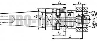
After regrinding, end mills change their working diameter. Therefore, to obtain the required width of the groove using a reground cutter, special chucks are used (see Fig. 5.17). The chuck consists of a body 1, into which a sleeve 2 is installed with a cutting tool 3. The cap nut 4 is designed to secure the sleeve in the body. The cutter is fastened to the bushing by screws 5. The axis of the bushing hole is shifted relative to the axis of the shank by an amount of e = 0.3 mm. By turning the sleeve in the housing hole, you can ensure a shift in the size of the milled groove (within 2e relative to the cutter diameter d). The amount of rotation is determined on a scale of 6. When securing the cutter, make sure that its tooth is located opposite the zero mark of the scale.
Rice. 5.17. The design of the chuck provides compensation for cutter wear
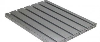
Milling of shaped grooves, T-slots and dovetail grooves is carried out according to various schemes.
Rice. 5.18. T-slot processing sequence
T-slots are usually machined in multiple passes. First, a groove is milled using a disk cutter (see Fig. 5.18, a), then the side surfaces are processed with a T-shaped cutter (see Fig. 5.18, b), then chamfers are removed using an angular cutter (see Fig. 5.18, c) and, finally , using a measuring cutter to ensure that the specified size B of the groove is obtained (see Fig. 5.18, d).
Shoulder milling
Two mutually perpendicular planes form a ledge. The workpieces may have one or more ledges. Processing of shoulders is a common operation, which is carried out with disk or end mills, or a set of disk cutters (Fig. 5.27, a - c) on horizontal and vertical milling machines in the same way as processing grooves. Large ledges are milled with end mills (Fig. 5.27, d).
Face milling cutters are used when milling workpieces with wide shoulders on horizontal and vertical milling machines. A part with symmetrically located ledges is processed on two-position rotary tables. After milling the first shoulder, the part in the fixture is rotated 180°.
For easily processed materials and materials of average processing difficulty with a large milling depth, disc cutters with normal and large teeth are used. Milling of difficult-to-cut materials should be done with cutters with normal and fine teeth. When milling a shoulder, you should take a disk cutter whose width is 5...6 mm larger than the width of the shoulder. In this case, the accuracy of the width of the shoulder does not depend on the width of the cutter.
Cutting blanks
The operations of completely separating part of the material from the workpiece, dividing the workpieces into separate parts, as well as the formation of one or several dimensional narrow grooves (slots, splines) are carried out with cutting and slotting cutters. The diameter of the cutting cutter should be chosen as small as possible. The smaller the diameter of the cutter, the higher its rigidity and vibration resistance. Workpieces are most often installed and secured in a vice (Fig. 5.28). It is preferable to cut thin sheet material and cut it into strips using down milling and small feeds (S_= 0.01…0.08 mm/tooth). Cutting speeds when cutting with cutting and slotting cutters made of high-speed steel, depending on the depth of milling and feed per tooth of the cutter, are: when processing workpieces made of gray cast iron v=12...65 m/min; from malleable cast iron - 27...75 m/min; made of steel - 24...60 m/min.