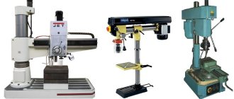
Correct installation of the machine in the workshop is an important stage in its preparation for operation. In this case, it is necessary to outline the installation location and select the type of foundation.
The machine workplace is mainly determined by the general layout of the workshop and the accepted principle of equipment arrangement (flow along the technological processing process or by type of equipment). At the same time, they strive to ensure the best illumination of the workplace with natural light during the day, the convenience of organizing the workplace (bedside table, places for workpieces and processed parts, crane service, communication with a passage or driveway), and also maintain standard intervals between adjacent machines and to supporting columns. When choosing the type of foundation, it was previously believed that all machines without exception must always be installed on a special foundation. This point was emphasized in supplier plant catalogs and in guidance materials from various design organizations.
When deciding how to install the machine (on an individual foundation or without it), a number of factors must be taken into account:
1. The nature of the load in the machine (static or dynamic). Machines with a static load conventionally include those whose speed of translationally moving parts does not exceed 3–8 m/min; their main movement is usually rotational; machines with a dynamic load include mainly planing, slotting, etc.
2. The rigidity of the machine bed, which depends on its shape and the overall dimensions of the machine. The most rigid frames are box-type. ENIMS considers the bed to be sufficiently rigid for light and medium-sized machines if the ratio of its length l
to height
h.
Machines with large dimensions usually have insufficiently rigid frames, especially if it consists of several parts connected at the joints with bolts, pins or keys 3. Accuracy of parts and operating mode - the higher the required processing accuracy or the more difficult the operating mode, the higher the requirements for the foundation .
4. Finally, you need to take into account the quality of the soil under the floor of the workshop where the machine is installed, the depth of its freezing in the area in winter, the presence of nearby installations that create strong ground vibrations, etc.
All foundations for machine tools can be divided into two main groups:
Group I – foundations that serve only as the basis for the machine;
Group II – foundations in the full sense of the word, to which the machine is rigidly connected with foundation bolts.
A foundation of any type allows the concentrated force from the weight of the machine to be distributed onto the ground in accordance with its bearing capacity and facilitates quick and reliable alignment of the position of the machine.
The purpose of the foundations of the second group, in addition, is to increase the stability and rigidity of the machine.
The machine receives additional stability because when additional mass is attached to the frame, the center of gravity of the installation is lowered and, in addition, stability is increased due to the foundation being covered on all sides by soil
Rigidity increases due to the stationary closure of the legs of the bed or the strengthening of its base, since the machine is firmly attracted to the foundation of the second group by foundation bolts. Due to the increase in mass, the frequency of natural oscillations decreases and attenuation increases, which leads to a decrease in the possible amplitudes of oscillations of the system. Finally, again, the effect of the soil surrounding the foundation is favorable, which dampens the vibrations of this system and protects it from shocks and vibrations of surrounding installations.
It should be noted right away that if the rigidity of individual machine components (support, table, console, headstocks) is insufficient, then unacceptably large vibrations can occur on such a machine on the most massive and reliable foundation.
Approximately, the foundation group, depending on the design features of the machine and its general characteristics, can be assigned according to table. 1. If the machine requires at least one of the characteristics of the foundation of the second group, then for it it is necessary to calculate and build the foundation of this group.
Table 1
| No. | Structural and operational features of the machine | General characteristics of the machine | Recommended foundation group |
| 1. | Degree of accuracy | Roughing machines | I |
| Normal precision machines | I | ||
| Precision machines | II | ||
| 2 | The nature of the actual effort | Machines with static main loads (most machines with main rotary motion). | I |
| Machines with dynamic main loads (machines with reciprocating motion: longitudinal and transverse planing, slotting and gear shaping, backing, broaching, etc.) | II | ||
| 3 | Machine weight | Lightweight machines weighing up to 2 tons. | I |
| Medium machines weighing from 2 to 10 tons. | I | ||
| Heavy machines weighing over 10 tons. | II | ||
| 4 | type of drive | Machines with built-in motors. | I |
| Machines with a separate electric motor or with a transmission drive. | I | ||
| 5 | Rigidity | Machines with rigid bed | I |
| Machines with insufficiently rigid frame | II | ||
| 6 | Insufficient stability (small base) | Some designs of radial drilling, aggregate and special machines. | II |
DEVICES FOR INSTALLING AND ALIGNING MACHINES
When installing, regardless of the foundation group, the machine must be accurately aligned to horizontal or vertical. To facilitate and speed up installation, special devices are used that are placed between the base of the machine and the foundation.
Flat metal pads with a thickness of 0.3–1 mm are currently almost never used due to a number of disadvantages:
a) adding or removing pads involves the need to lift the machine each time, which is done either with a crane or crowbars manually, which is always accompanied by the danger of moving the machine from its installation site;
b) stepwise adjustment and the need to have a large set of different pads, which are easily clogged, bent, or lost;
c) the rigidity of installation on such pads is insufficient due to numerous joints and insufficient smoothness and straightness of the pads.
| Rice. 3. Steel wedge |
Setting wedges (Fig. 3) are widely used for installing light and medium-sized machines of normal and reduced accuracy. Wedges are placed around the perimeter of the base at intervals of 500 - 600 mm. If the machine is installed on the foundation of the second group, then the wedges should be located as close as possible to the foundation bolts. When aligning, the position of the machine can be smoothly changed by tapping wedges.
| Rice. 4. Installation shoe |
Installation shoes are used for mounting medium and large machines. They can also be used to install precision machines. The shoe consists of a durable body and a wedge (Fig. 4), which can be moved with a screw using two nuts. In this case, the screw does not bend, since it can move freely along the vertical slot of the rack. Oblong holes in the wedge and the base of the shoe allow the foundation bolt to be passed through them freely, if necessary.
At the end of the alignment, the screw is firmly locked with the same two nuts. The figure shows the approximate dimensions of an average shoe. Installation shoes are placed at intervals of 1 - 1.5 m but not less than three or four under the machine.
| Rice. 5. foundation slab element |
Foundation slabs are used exclusively for the installation of large and especially precision machines. The foundation slab is made of fairly massive cast iron (Fig. 5). In relation to the machine being installed, shoes similar to those discussed above are built into the plate every 1–1.5 m. The slab is embedded in the upper part of the foundation during its laying and is connected to it either with special dowels protruding from below, or is attracted by special bolts embedded in the masonry. The entire foundation plate protects the machine from deformation in the event of uneven settlement of the foundation. In all cases, it is easy to make the machine horizontal by adjusting the shoes.
Convenient, but less common means of machine alignment include alignment using bolts located at the edges of the base of the bed along its entire perimeter. The machine in this case rests on the supporting ends of the bolts, which in turn must rest on sufficiently thick steel plates. Once the machine has been aligned, the bolts are secured with locknuts.
The second group of devices for installing machines consists of foundation bolts. They must provide a sufficiently rigid and strong connection of the frame with the foundation of the second group. The clamping force developed by the bolts, together with the weight of the machine, causes frictional forces between the base of the frame and the foundation, which always exceed the shear forces that can arise and act on the machine. This is also facilitated by the cement bead formed after gravy around the sole of the machine. Therefore, foundation bolts only work in tension. From experience it has been established that foundation bolts with a diameter of less than 14 mm should not be used, since they become deformed (“flow”) when tightened. When fastening light and medium-sized machines with foundation bolts with a diameter of more than 14 mm, they are usually not checked by calculation. It is recommended to calculate bolt diameters for heavy machines.
Rice. 6 Mounting unit of the machine on the foundation of the second group |
The length of the foundation bolts is determined from the condition of equal strength of the bolt in tension and the strength of the foundation masonry in tension. The section of the masonry working on tearing is taken in the form of an overturned truncated pyramid (Fig. 6) with an angle of 2p at the apex.
In table Table 2 shows the values of the minimum embedding length of foundation bolts for various masonry materials, obtained on the basis of calculations.
table 2
| Diameter of the foundation block, mm | Foundation material | ||
| Concrete | Brick | Booth | |
| 14 | 140 | 160 | 300 |
| 16 | 170 | 200 | 350 |
| 18 | 190 | 260 | 450 |
| 22 | 250 | 280 | 450 |
| 24 | 260 | 300 | 550 |
| 27 | 280 | 320 | 550 |
| 30 | 320 | 360 | 550 |
| 36 | 380 | 420 | 750 |
| 42 | 460 | 500 | 750 |
| 48 | 500 | 600 | 850 |
To ensure reliable fastening, the edges of the wells for the bolts are made with a slight slope.
In fig. Figure 6 shows a correctly completed filling of the machine with cement mortar.
Structurally, foundation bolts differ mainly
design of the tail section (Fig. 7).
There are foundation bolt designs that do not require grouting; such bolts are called anchor bolts and can be easily dismantled.
When laying a foundation near the bottom of a straight well, an anchor plate is sealed (Fig. 8), onto which a bolt is then attached. To do this, pass the rectangular head of the bolt through the same hole in the plate and then turn it 90° until it stops. After this, the bolt is tightened in the usual way.
Rice. 7.Structural types of foundation bolts |
All other things being equal, the length of the anchor bolt can be taken less than the length of the foundation bolt, since the anchor plate increases the surface of the section of masonry to be torn off.
Anchor bolts are rarely used and only for fastening heavy machines.
Sharpening tool
For abrasive sharpening of the cutter, a sharpening machine or lathe can be used. For carbide tools, green carborundum of medium hardness is used. For initial processing, the abrasive value of the wheel should be 36-46, at the end of the process - 60-80. For high quality sharpening, a whole circle is required, without defects and geometry violations.
Diamond wheels are also widely used for sharpening turning tools, which ensures high cleanliness of cutting surfaces. In comparison with carborundum wheels, the surface cleanliness of the cutter increases by two classes, and work productivity increases. The use of diamond wheels also increases the service life of the tool - the possible number of cutter regrinds increases by 20-30%. But it should be taken into account that it is economically feasible to use sharpening with a diamond tool with an allowance of no more than 0.2 mm. For larger values, preliminary sharpening with a carborundum wheel is recommended.
INSTALLATION OF MACHINES ON FOUNDATIONS OF THE FIRST GROUP
| Rice. 8. Fastening with an anchor bolt |
As indicated, such foundations serve only as a basis for machines. Their role is usually played by the cement floor of the workshop or a concrete base on which a wooden block is laid. It is not recommended to install the machine directly on a checker, since the machine is difficult to align, alignment is quickly disrupted, the machine is unstable, warps and deforms. There is no justification for the long-term violation of this provision at a number of factories, where many machines are placed directly on the end block, while knocking them down with wooden wedges. Wedges are often splintered and crushed by the machine. The installation is disrupted even more quickly when emulsion gets on the floor, which to some extent always occurs in industrial conditions.
In multi-storey buildings, the installation of machines is also carried out on inter-storey floors, which, of course, is less desirable and requires additional calculations [4].
The foundations of the first group also include separate rigid slabs, on which the machine can be quickly aligned and which reduce the specific pressure on the ground. The minimum depth of the foundation of such slabs, reaching dimensions of 4x4 m2, is determined by the depth of the plant layer of soil. Their relatively low weight allows them to be made mobile. With all movements of the machine that occur during the redevelopment of the workshop, the slab is moved along with it. This makes the work much faster and cheaper.
When designing all foundations for machine tools, similar to the practice of construction design in general, first, for structural reasons, acceptable dimensions of the foundation are outlined, and then a verification calculation is made. The calculation of the foundation slab consists of several stages.
First stage
. The contour and dimensions of the slab are outlined in plan, based on the shape and dimensions of the machine sole. In this case, the contour is simplified as much as possible. In addition, the slab must be designed so that the weight of the machine with the slab is distributed as evenly as possible on the ground, i.e., so that the resultant force of gravity is applied centrally.
The indicated provisions of the first stage are valid not only for rigid slabs (foundations of the first group), but also for foundations of the second group.
| Rice. 9. Scheme of the action of design forces on the slab - the foundation of the first group. |
Second phase.
The height (thickness) of the slab is calculated based on the following two considerations:
1) the foundation slab is considered as a rigid beam; finite length on an elastic base;
2) the load on the slab is taken to be applied in the middle of its length (Fig. 9).
This situation can be created when the machine is lowered by a crane and briefly placed edge-on on the slab.
Bending stress in the middle cross section of the slab in the absence of cracks
, t/m2,
where M
=0.15
qBL
– bending moment, tm;
– moment of resistance of the cross-sectional area, m3;
– load per unit width of the slab in t/m;
G
st – weight of the machine, t;
L
,
B
,
h
– length, width and height of the slab, respectively, m;
R
z – permissible bending stress for the slab material in t/m2.
After substitution we finally get
, kg/cm2.
h is determined
.
Taking R
z=24 t/m2 for brickwork
R
z=18 t/m2 for rubble masonry and taking into account some production and design considerations, it is recommended to take the thickness of the slabs no less than that indicated in the table. 3.
Table 3
| Name of foundation material | h , cm |
| Concrete and reinforced concrete | 15 |
| Bud-concrete | 60 |
| Reinforced brickwork | 38 |
| Brickwork | 45 |
| Rubble masonry | 65 |
Third stage
. Perform a verification calculation of the specific pressure on the ground
, kg/cm2
where G
– total weight of the machine, the foundation slab and the heaviest workpiece, kgf;
F
Ф – area of contact between the foundation and the soil, cm2;
R
d – permissible pressure on the ground, kg/cm2;
R value
d for some soils are given in table. 4. When the load on the foundation is applied off-center, the pressure on the ground in some places turns out to be much greater than the average calculated one, as a result of which soil settlement, distortions of the foundation, the appearance of cracks in it, deformation of the machine, etc. are possible.
Table 4
| Type of soil | Soils are dry or naturally moist | The soils are very damp and wet | Thickness of the layer below the foundation, m | ||
| Angle of repose j0 | R d, kg/cm2 | Angle of repose j0 | R d, kg/cm2 | ||
| Vegetable soil, black soil | 40 | 1,0 | 33 | 0,5 | – |
| Clay soil, medium-density loam | 40 | 2,5 | 30 | 2,0 | 2 |
| Densely compacted clay and loam | 45 | 3,0 | 30 | 2,8 | 2 |
| Medium coarse sand loosened | 37 | 2,0 | 33 | 1,5 | 1 |
| Medium coarse sand densely compacted 5.0 | 45 | 2,5 | 33 | 2,0 | 1 |
| Medium-sized, densely packed pebbles | 40 | 5,0 | 35 | 4,0 | 4 |
| Sandstones, limestones of medium hardness | – | 12–13 | – | 12–13 | 3–4 |
| Note. The angle of repose is the angle formed with the horizontal line by the free lateral surface of an embankment made of earth or other bulk materials in a state of equilibrium. |
If for some reason it is impossible to avoid the off-central load application, then, knowing the approximate magnitude of the displacement, it is necessary to determine the maximum specific pressure that can arise under the foundation. The calculation is made using the formulas for the resistance of materials for the extreme points A
B
of the support
A B
.
where e
– the magnitude of the displacement of the point of application of force from the center of the foundation slab; the remaining designations are the same as the previous ones.
The largest value found must be less than the permissible specific pressure.
In Fig. Figure 10, a, b, f shows pressure distribution diagrams under the support for several typical cases of eccentric load application.
Under almost any forced installation conditions of machine tools, eccentricity should not exceed the following limits:
.
Fourth stage.
The foundation is checked for crushing under the installation elements (wedges, shoes) according to the formula
, kg/cm2
where is the static load on one pad, kg;
– the weight of the machine with the heaviest part, and for machines with dynamic loads – taking into account the latter, kg;
n
– number of pads around the perimeter of the machine base;
F
– area of the base of the lining, cm2;
Raop
– permissible bearing stress, which for all foundations can be taken equal to 8–10 kg/cm2. If the weight of the machine is distributed unevenly on the pads, then check the most loaded pad. For example, on lathes, approximately 70% of the weight is on the front stand and about 30% on the rear stand. In the place of the greatest load, you should either place pads more often, or use pads with a larger base area. When calculating, dynamic loads can be conditionally reduced to equivalent static loads:
1) during reciprocating motion, the equivalent static load should be taken equal to five times the value of the inertia force and should be assumed to be applied in the direction of the actual inertia force;
2) during rotational motion, when the dynamic load is caused by centrifugal forces of unbalanced rotating masses, the equivalent static load should be taken equal to 20 times the weight of the workpiece and assumed to be applied in addition to the weight of the part
When installing machines on foundations of the first group, the role of the foundation itself is actually played by the frame. It absorbs all loads and ensures normal operation of the machine. When the frame cannot fully ensure this, they resort to partially securing the machine to the foundation of the first group by adding cement mortar. No other additional fastening is performed. Fastening with one grout is especially widely used for machines installed on interfloor ceilings.
Adding cement mortar allows you to distribute the weight of the machine over a large area, fix the position given to it by the installation elements during alignment, and protects the machine from lateral shifts. To carry out the gravy, wooden formwork is made around the supporting part of the machine. The space formed by the formwork is filled with cement mortar with the expectation of pouring it under the entire sole of the machine and forming a collar 10-20 mm high around the base of the bed. Grouting is done with cement mortar 1:3 (ratio by weight of cement and sand).
Why vibration support is a bad option
The foundation of the machines is, as a rule, 1-2 or more meters of concrete, in which anchor bolts are fixed. The machine is leveled and then firmly screwed to the foundation. In this case, the tightening torque of each support affects the overall geometry of the machine. Therefore, the installation of a machine requires a very highly qualified specialist - a commissioning operator, who understands how the machine behaves when tightening or loosening a particular attachment point. When installed correctly, the machine has an ideal geometry, and the rigidity of the foundation increases the rigidity of the machine. As a result, processing accuracy is increased and wear on the machine guides is minimized. If vibration supports are used, the machine bed “walks” under load, which negatively affects both the quality of the manufactured part and the service life of the machine itself.
INSTALLATION OF MACHINES ON FOUNDATIONS OF THE SECOND GROUP
Often machines are attached with foundation bolts to common foundations, i.e. to a concrete floor or interfloor ceiling; At the same time, wells are punched under the bolts. The machine is placed on channels No. 10 or 12, since it can be aligned faster and more conveniently on them, cement flows better under the machine, and after installation the machine is equal to or even slightly higher than the level of the wooden floor covering.
If there is no concrete foundation under the wooden flooring of the workshop, then foundations in the form of concrete strips or strips 1.2–3 m wide and 20–40 cm or more thick are sometimes used under the machine line. For them, a ditch 15–30 cm deep is selected in the ground.
The following technique is used even more widely. Having removed the flooring, the soil at the installation site of the machine is somewhat cleaned. Then, several sections of channels or I-beams of the same number are placed directly on it, according to the shape of the base of the machine. If the channel is not placed on a shelf, but laid flat, then steel plates are first placed under it on the ground. The machine is aligned on the channels using wedges. Small foundation bolts are placed in the holes of the frame, and formwork of sufficient height is made around it from boards. In this case, the edges of the formwork should be at least 10–15 cm away from the edges of the frame. Then the machine is filled with cement mortar, and after the cement has set, after a few days the foundation bolts are finally tightened. The wooden floor covering is restored close to the created base, on which formwork is sometimes left.
However, the most typical foundations of the second group are foundations in the form of separate arrays for a particular machine. Their calculation, similar to the calculation of the foundations of the first group, consists of a number of stages.
First stage.
The outline and dimensions of the foundation are outlined in the plan in the same way as was indicated when calculating the foundations of the first group. In this case, the distance from the edge of the base of the frame to the edge of the foundation must be at least 10 cm.
Second phase.
Set by the weight of the foundation.
For machines with a static load, it is usually equal to 0.6–1.5 of the weight of the machine; approximately it is better to take it within the range of (0.8 – l.0) G
art.
For machines with a predominant dynamic load, the weight of the foundation is taken to be greater, on the order of (2–3) G
Art.
Third stage.
Calculate the height of the foundation
N
F, knowing its weight
C
F, plan view with area
F
F> and the specific gravity of the material gF:
.
Next, check the resulting value H
F according to other factors influencing the height of the foundation, and if it does not satisfy them, then it is adjusted upward - in this case, the weight of the foundation must also be recalculated.
1. The depth of adjacent foundations should be such that the angle 9 between the overlying or underlying foundations (Fig. 11) does not exceed the angle of repose. In this position, the direct influence of the foundations on each other due to soil subsidence is eliminated.
| Rice. 11 Dependence of the foundation depth on the depth of adjacent foundations. |
2. In unheated rooms, the foundation must lie to a depth of at least 0.7 of the soil freezing depth in the given area, and in heated rooms, at least half the freezing depth. The approximate freezing depth can be taken from the table. 5.
Table 5
| Characteristic points of the area | Soil freezing depth, m |
| Arkhangelsk, Izhevsk, Komsomolsk, Chelyabinsk, Omsk, Barnaul, Novosibirsk, Yekaterinburg, Magnitogorsk, Kuibyshev | 1,6 |
| Saratov, Volgograd, Karaganda, Petrozavodsk | 1,4 |
| Moscow, St. Petersburg, Nizhny Novgorod | 1,2 |
| Kyiv, Kharkov, Talin, Alma-Ata | 1,0 |
| Dnepropetrovsk, Lvov, Minsk | 0,8 |
| Odessa | 0,5 |
3. The height of the foundation must be sufficient to allow wells for foundation bolts. The minimum depth for embedding bolts in the foundation, depending on the diameter and material of the foundation, is taken according to table. 2.
4. The height of the foundation must be sufficient so as not to cause bulging of soil on the sides; it must satisfy the formula of prof. Belzetsky:
,
where, sz is the specific pressure on the soil, t/m2, obtained under the foundation with the selected dimensions of the foundation;
g – volumetric weight of soil, t/m3;
j – angle of repose in degrees;
b – foundation width, m.
Fourth stage.
The pressure of the foundation on the ground is checked in the same way as indicated for rigid slabs - foundations of the first group.
If the specific pressure turns out to be unacceptably high, the area of the foundation base should be increased without changing the upper base (Fig. 12, a). Expanding ledges turn out to be quite strong when the following ratio is maintained for their sizes:
.
If, with an increase in the base area, it is desirable to increase the weight of the foundation, then it is given the shape of a trapezoid (Fig. 12, b).
Fifth stage
. The foundation is checked for collapse of the material under the installation elements (similar to the instructions in the fourth stage of calculating rigid slabs). In fact, the check is only needed for the installation period, since on the foundations of the second group, the machines are always topped up with cement mortar after installation.
| Rice. 12. Forms of foundations with an enlarged base |
Dynamic calculation of the foundation is done only if there is a danger of resonance, i.e., the disturbing frequency of the machine (for example, one of the revolutions) coincides with the natural frequency of the foundation. The latter should be 50% lower or 30% higher than the disturbing frequency. If necessary, the dynamic calculation is included as a final part in the third stage of the calculation.
There are still no specially developed methods for calculating foundations
metal-cutting machines for resonance, so they are calculated similarly to foundations for other machines. For example, foundations for turning, milling, boring, grinding and other machines are calculated similarly to foundations for turbo generators, for slotting machines - like for sawmill frames, and for planers - like for horizontal piston machines. If necessary, such calculations can be found in the literature.
With significant changes in temperature in the workshops, the frames of large machine tools installed on the foundations of the second group may receive noticeable thermal deformations. Therefore, during periods of the most dramatic temperature fluctuations, the frames should be allowed to deform freely; To do this, the foundation bolts are briefly loosened and then tightened while monitoring the position of the machine using instruments. The danger of deformation of the machine is eliminated if a relatively constant temperature is provided year-round at the installation sites (within 14–28°). For these purposes, in winter, all entrances should be equipped with thermal air curtains, entrances with multi-chamber vestibules, and in summer, the premises should be effectively ventilated and the outside painted in light colors.
Types of bases
To install the units, different foundation structures are used that meet the requirements set by the standards.
In practice, machines are installed mainly on the types of support structures presented in the table below.
| № | Type of foundation structure | Characteristics of the constructed base |
| 1 | slab foundation without basement | it is poured only on the ground floor, it is expensive due to the significant consumption of building materials and high labor costs, but its massiveness well dampens the resulting vibrations |
| 2 | frame base equipped with a grillage of beams | is capable of withstanding high-frequency vibrations without negative consequences, therefore it is often used for the installation of impact mechanisms |
| 3 | wall support structure (is a modification of strip-type bases) | it is erected from the second floor, the effective load from the units with this support structure is taken by the external (load-bearing) walls, as well as internal partitions |
| 4 | base-floor with a basement | is located above the first floor, transmits vibrations (arising during the operation of machines) to the interfloor floors (building frame), and is capable of withstanding only static loads or vibrations with insignificant amplitude |
The most modern option for light or medium-heavy mechanisms is to install bases with springs or other types of vibration supports that dampen vibrations that occur during operation of the units. Dampers (vibration dampers) can be especially easily installed under frame-type bases.
At its core, a floor foundation equipped with a basement is the same slab, only built from ready-made reinforced concrete blocks laid on floor beams.
The given foundation structures are divided into 2 types:
- basementless (it almost completely lacks a part located above the floor);
- basement (with a well-developed above-ground section).
The latter option can have a wall or frame form. It is characterized by a large height above the floor plane.
Foundations by design can also be prefabricated, monolithic, prefabricated-monolithic. They come in the following forms:
- rectangular;
- tape;
- stepped;
- shaped;
- trapezoidal.
It is possible to use piles of different types as foundations for units with periodic loads. A slab or strip grillage is installed on top of the supports. Impact-type mechanisms must be mounted on solid reinforced concrete piles.
The distances between installed pillars are regulated by SP 24.13330. It should not exceed 10 of their diameters. The vibrations of pile foundations can be calculated using the relevant subsections of this document.
Various blocks and slabs (hollow or solid) are used as elements of prefabricated structures.
Individual and group foundations
The equipment is mounted on individual or group foundation structures.
Group foundations are designed for installation of several mechanisms of light or medium weight (up to 8 tons) with a rigid frame and normal operating accuracy, operated with a predominance of static forces. Their thickness is usually 150-250 mm. They often serve only as bases. The single support is mainly concrete (or reinforced concrete) floors. But in practice there are other design options.
Mechanism frames are considered rigid when the ratio of their length to height is no more than 2 to 1.
Individual type foundations are built for precision equipment with medium or heavy weight, which operates with dynamic loads of moderate or significant magnitude. Such supports, in addition to removing vibrations from machines and ensuring their correct working position, also isolate the units from each other. This prevents the transfer of vibrations between them.
Lightweight machines, or medium-weight units with a predominant static type of load, are often mounted directly on the floor or interfloor ceiling (the so-called foundation of the first type). If necessary, such a base is reinforced with a concrete screed (while laying reinforcement), also increasing its thickness.
BASIC INFORMATION ABOUT LAYING FOUNDATIONS AND INSTALLING MACHINES
The material for especially critical foundations and rigid mobile slabs (the latter weighing up to 5 tons) is reinforced concrete or concrete grade 110. The ratio between the volume of cement and filler (crushed stone) ranges from 1:5.5 to 1:7.5.
Conventional stationary foundations are laid out of baked bricks or rubble. For large electric motors (over 20 kW) and auxiliary mechanisms standing separately near the machine (supports for supporting rods in turret machines and automatic machines, installation of a DC motor-generator, etc.), separate foundations are made, which should not be connected to the main foundation machine
Foundations in the form of separate arrays or strips should not come into contact with the floor of the workshop or other elements of its structures. The resulting side cracks are filled with slag or sand.
In case of rocky or weak or heterogeneous (filled from construction) soils, a cushion of sand, slag or gravel is first made in the hole under the foundation. When making it, the selected material is poured in layers of 10–15 cm, each time pouring water on it, followed by tamping or compaction with a vibrator.
Wells for foundation bolts most often have a cross-section of approximately 80x80mm (Fig. 13) and are located in accordance with the holes in the machine frame. In this case, the thickness of the well walls z
everywhere there should be at least 150 mm for concrete foundations and at least 250 mm for brick foundations.
| Fig. 13. Layout of wells for foundation bolts |
To form wells during laying, wooden plugs of the required shape and size are placed in the foundation, which must be removed 2–3 hours after concreting.
Installation of the machine on the foundation can begin 3–5 days after the completion of the masonry.
When installing, foundation bolts are inserted into the holes in the frame of a raised machine, a nut is completely screwed onto each, after which the machine begins to be lowered onto the foundation, directing the bolts into the wells. When the machine has not yet completely reached the foundation, wedges or shoes are placed under its sole. Placing wedges near the foundation bolts is mandatory.
Then the machine is finally lowered and aligned for horizontal or vertical alignment. The usual accuracy of installation of normal machines in the horizontal plane is from 0.04 to 0.02 mm per 1000 mm of length. The calibrated machine is then filled with cement mortar, simultaneously filling the wells with foundation bolts. In this case, the wedges are poured entirely, while for the shoes only the base is poured. It is necessary that the surface of the foundation for the gravy is notched. Aging after gravy is also 3-5 days.
Once the cement has “set”, the machine is finally secured by evenly tightening the nuts of the foundation bolts. To avoid distortions, the position of the machine should be simultaneously controlled in the longitudinal and transverse directions by levels.
When machines are mounted on easily deformable bases or on moving devices (cars, railway platforms, ship decks), they should be installed on only three support points. With this method of fastening, the equipment is given a fairly stable position and, at the same time, when the base (floor) warps, the possibility of its significant deformations, which would necessarily occur in these cases with other fastening methods, is excluded.
How to build it yourself
A normal machine costs at least 50,000 rubles. If you assemble it yourself, this amount will be significantly reduced.
Attention. To make a homemade lathe, it is advisable to use standard drawings
There are all the dimensions of the parts and the order of assembly.
These drawings can be improved. For example, it is worth adding an emergency shutdown button, a thermal relay that protects against overheating, and a protective casing.
Selection of parts
Certain elements of the device will have to be purchased assembled, such as the motor and clamp. Some are purchased separately and ordered in workshops, where they will be made to the required dimensions. The better the steel used, the longer the machine will last.
Base
The best choice would be to use a cast frame from an old non-working machine. The stability of the unit depends on the base. As an alternative, you can weld a frame from channels or profile pipes. You cannot take wood, as it will not be able to withstand the workload.
Electric motor and transmission
For the engine, you can use a device from an old washing machine or other household appliances that have sufficient power. It is also worth considering purchasing a new engine, since the price is not too high.
It is better to use a belt drive. It is much easier to assemble. Also, when using a belt directly on the shaft, there is less impact, and this significantly increases the service life.
Master and slave centers
These two nodes are placed on the same axis. There is also a type of machines that have one leading center. The follower must be placed on the tailstock (it can be rotating or stable). The sharpened end of the bolt is suitable for manufacturing.
The need to secure equipment
One of the fundamental factors for the production of a foundation for a machine is its purpose. The machine is secured to the floor mainly if it is intended for the production of parts with micron accuracy.
Provided that the equipment is mobile and periodically moved, a separate foundation is not required for it; its installation requires a perfectly flat concrete floor or a concrete panel lining, about 15 cm thick. Considering the weight of the equipment, up to 30 tons, its stability cannot be considered worry.
In order to avoid emergency situations in the workshop, turning equipment still requires its own foundation with the laying of routes for communication components that ensure its functionality. Metal pipes for hoses for supplying air, water, and electricity with a voltage of 380 V will reliably preserve the insulating layer and the wires and hoses themselves from deformation.
The height of the platform will depend on the diameter of the pipes and the weight of the equipment. The foundation area is calculated for each piece of equipment separately, which is why it may not have a strict quadrangular shape. It may appear to be created from individual elements put together into a cohesive whole. Despite this design, it is poured in a single slab, and not for each unit separately.
One of the requirements for the foundation for a lathe or an entire complex is that the platform protrudes from under each unit on all sides of the same width.
Cost of disassembly process
The final price of work on dismantling the machines is influenced by:
- complexity of the operations (number of floors, uneven floors, etc.);
- dimensions and weight of equipment;
- cost of the dismantled line;
- process maintenance;
- the need for additional work.
When carrying out dismantling operations, the Takelazhniki.ru company takes full responsibility for the integrity and safety of the cargo. This segment of work requires specific skills and knowledge, which our employees fully possess.
Regulations for arrangement
Above we discussed the basic requirements that any foundation intended for installing industrial equipment on it must satisfy. However, there are other requirements - for the foundation for equipment with dynamic loads, which it must meet.
Design work, as well as the practical part of arranging the foundation, should be carried out only by competent specialists who, in addition, also have experience in carrying out this type of work. In order to create a correct and complete project, it is necessary that all the required data is available. During the construction of the foundation for the equipment, it is necessary to periodically carry out quality control. It is very important that the actions of all participants in the work process are strictly coordinated. Those foundations that have already been erected should be used only with the equipment for which they are intended. There is technical documentation for this. For construction, you can use only those materials that are suitable according to the design documentation. In the future, it is necessary to carry out maintenance of the foundation so that the structure can be used for as long as possible. It is recommended to use the simplest possible parts as fastenings.
For example, these could be anchor bolts that are embedded in concrete.
Commissioning
Commissioning work is usually carried out by representatives of the manufacturer, but sometimes this function is performed by an employee of an enterprise that has passed the appropriate licensing. Commissioning consists of mutually interfacing the machine components and setting up functional blocks according to the technological map approved by the plant where the machine will be operated.
In addition, the service technician programs the machine's numerical control and optimizes software parameters.
