05.06.2020
The machine allows you to process parts for a wide variety of purposes. Modern universal models have many parameters, with the help of which work with products is carried out without difficulties. But this tool also has a vulnerable aspect - interaction with objects of inappropriate shape. A lathe chuck faceplate is an easy solution in situations like this.
Large products do not fit into the machine itself, so it is impossible to secure them in the required position. As for non-standard shapes, usually the clamping device, which acts as a fastening element, damages them. Squeezing is not very good for flat materials, the edges may crack or bend. It is especially unpleasant when various fittings are located in these places. And the object itself is quite capable of being damaged in such a situation. Accordingly, it is strictly not recommended to start processing without a specialized adapter.
Why do you need a faceplate on a lathe?
If there is a displacement along the spindle axis, as well as other obstacles to normal fastening through the chuck jaws, then installation of an adapter is mandatory. Fixation to the disk occurs through pressing against the equipment. If it is impossible to do this without damage, then there are variations of various fastenings that have strict specialization. Numerous offers on the market allow you to select fasteners for almost any model. However, no one bothers you to make calibrated fasteners for a specific task.
After installing the disk, it is imperative to make sure that the correct axial position is maintained. Indeed, unlike insertion directly into the cartridge, the indicated technique does not at all guarantee automatic centering. Therefore, you will have to do a little reconciliation.
It is noteworthy that the adapter faceplate can also help out in a situation where you have to interact not with the unusual shape of the part, but with a non-trivial cutting tool. That is, the blade device is already attached. But this is a fairly rare situation.
What kind of node is this, what is it for?
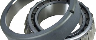
A lathe chuck is a device designed for mounting a workpiece on lathes, special, and universal machines. The chuck itself is rigidly connected to the spindle and transmits torque to the parts.
To produce surfaces of the correct round shape, the part must be aligned exactly in the axis of rotation of the spindle and have no runout. It is most convenient to mount round workpieces, hexagons, into a self-centering chuck. The best option for such a chuck is a three-jaw chuck. Compressed from three sides, the workpiece itself takes the desired position.
In mass and small-scale production for the manufacture of small and medium-sized parts such as shafts, a chuck with a body diameter of 160 mm is used. The Archimedes spiral installed inside converts the weak muscular force when turning the gear with a key into a strong force that presses the cams to the part. As a result, the workpiece is manually firmly secured in the chuck and can withstand the stress of processing.
Important!
The three-jaw chuck allows for quick installation and removal of parts, increasing worker and equipment productivity.
Design
It makes no difference which machine is used: metal or wood. This device for securing objects is suitable in both situations. The most common discs are made of steel and cast iron. Grooves and recesses are made on them. The main goal is reliable fixation of the object. Depending on which grooves are located on the surface, there is a certain list of shapes with which a given fastener is allowed to interact.
In addition, the equipment itself is often connected to the spindle using hubs. But the models that are mounted on the cartridge are easy to distinguish. The hubs do not look like cones, they are strict cylinders.
In many variations, the size of the faceplate allows you to install additional clamps on it. Usually clamp type. Then the future product is clamped according to the principle of a vice if it has protruding parts that ignore the mechanical compression pressure.
Do not forget that atypical processing is always a certain risk. The manufacturer did not intend such an action, which means there is a possibility of destruction of the product upon startup. And also the scattering of fragments over a large area. Accordingly, the main weapon in this case is a thorough balance check, calculation, and test run. Theoretically, a danger also arises for the equipment; it can be damaged if the fasteners are set inaccurately.
Attention and caution are the main rules that must be followed.
Horizontal boring machines
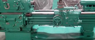
The main distinctive feature of a horizontal boring machine (Fig. 1) is the horizontal arrangement of the spindle. This type of machine is somewhat reminiscent of a conventional screw-cutting lathe. But there are several key differences in a horizontal boring machine. Firstly, the tailstock is missing. Instead of the tailstock, a movable rest is installed. Secondly, the faceplate with which the spindle is equipped has the ability to shift the cutter relative to the axis of rotation, which is not typical for a lathe. Thirdly, there is a table on which the part can be fixed.
Figure 1. Horizontal boring machine
Let's look at the main components and elements that make up a standard horizontal boring machine.
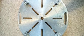
Figure 2. Boring machine faceplate.
Today, horizontal boring machines that are equipped with a numerical control module are becoming increasingly common.
Types and purpose of faceplates
Many people mistakenly believe that this item is becoming a universal way to solve any problem of processing atypical parts. But to check, this adapter is very strictly specialized. In other words, to work with a certain category of forms you need your own row of disks.
Of course, one option is quite capable of working with a whole range of parts of similar dimensions at once. But the specifics still remain very clear. Accordingly, there are a number of different adapters that differ in:
- Purpose.
- Structural parameters.
- Fastening the faceplate.
- Even production materials.
Therefore, you should always have a whole set on hand, which implies different purposes. Moreover, some of them are homemade. And not only because saving is a great solution. There are also more prosaic reasons. Some unexpected variations may simply not be available on the market or in the assortment of the nearest supplier. We will talk about making such a tool below. Now let's move directly to species diversity.
T-slot disc
The structure has a surface on which the recesses are located. And the fastening is ultimately done using screws. This is perhaps one of the most universal types. There are a huge number of types of products that can be easily installed on such equipment.
The quantitative factor of the grooves also changes. The more there are, the greater the broad purpose implied. Even at the manufacturing stage, the disk parameters are easily adapted to the current situation. Thus, this method is most often used.
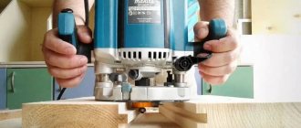
This is a good option as a faceplate for a milling machine. However, as already indicated, a wide variety of uses are allowed.
With through grooves
The universal choice for metal processing. Suitable for wood, but there are fewer advantages. The main difference is the presence of through grooves. Their magnitude and frequency are determined by the task. Typically, all holes are located around a circle, at a certain radius. And sometimes you come across models where the groove is solid, representing a continuous semicircle.
Installation is done using screws. Often the part itself is placed directly on the disk with its reverse side. If for this purpose there are corresponding holes already in the product itself, of course.
In most cases, other mechanisms are installed on the surface of the adapter. They allow you to diversify the range of clamps with which the disc can interact and increase the adhesive capabilities.
With holes
The entire line of species in this category has one thing in common - a recess in the center. After all, with its help the disk itself “sits” on the cartridge. Accordingly, thread is used. But the remaining holes are located under already defined regulations. Whichever product line is intended to work, there will be so many grooves. Round, oval, and elongated options are used.
There are differences in how the workpiece is secured to the faceplate. Objects can be fixed not only with screws, but also with clamps, which greatly expands the variability.
Leashes
When it is intended to place a part between centers, the transmission of torque from the shaft to the product is ensured by just this type of disk. They are equipped with a special recess along their entire circumference, which is designed to hold the clamp. It encircles the future product, becoming something like a muff.
In addition, for fixation, there are different holes on the disk, usually in a T-shaped format. Their exact number varies within a free range. In fact, the drive faceplate does not have strict parameters in this regard; it all depends on the purpose.
With a square
The additional adapter is often shaped like an angle. It is attached to the disk part, leaving an empty flat surface on the other side. The workpiece is located on it. The meaning of this additional element is to reduce the mechanical factor for the object. Accordingly, it should be used if the product is vulnerable, has soft parts, or thin areas.
To ensure maximum stability, it is important to install fixation not only at one point on the surface, but to select at least three. More is acceptable, it all depends on the characteristics of the material used. It is also logical to use additional fasteners. For example, if the shape is thin and elongated, then a special adapter is suitable. The purpose of the faceplate trident chuck is to work with long wooden structures with a flat base.
Universal and special
Considering the fact that there are already many described variations of different models, manufacturers often try to minimize their diversity. Therefore, they create sets of universal adapters. Their essence is to minimize the wasted material. That is, one basic disk is produced, which, with the help of a device, becomes any of those described above. Fixing elements and teeth are installed on it.
It turns out something in the style of a screwdriver with a base and a dozen attachments. If you need a flat one, it’s easy; if you need a cross one, it’s even easier.
And special ones are washers made for a specific batch according to a special drawing, which will be useless in another production.
Diamond boring machines
Diamond boring machines (Fig. 4) are designed for final (fine) processing of parts.
Figure 4. Diamond boring machine.
The diamond boring machine consists of the following main components.
In addition to good processing accuracy, the diamond cutter provides a high class of surface finish. These machines are used where high purity and precision of processing are required, for example, in automobile and aircraft engines, machine tool parts, and control and measuring equipment.
Source
Operating rules
Let's briefly go through the main nuances of how to install and work with such an element, depending on the equipment.
On universal
In principle, what is a faceplate for a metal lathe chuck? It is an adapter with a special type of clamps. But at the same time, he himself is placed on the base according to different laws.
- An uneven surface, asymmetrical, always implies mounting on a clamp.
- To straighten the axle, you need to use lifting bars.
- Use a counterweight (usually included) to avoid vibration.
On rotary turning machines
There are fundamental differences here. If we constantly mentioned above that the washer is simply an additional adapter designed to simplify work with unusual workpieces, in this case it is the main element of the fastener. After all, the machine itself is a round table, on top of which a disk with several bushings is placed. Objects are mounted on them. What’s interesting is that even if the bushings themselves break or become unusable, they are replaced separately. And it becomes a kind of working surface that cannot be changed.
Self-centering washers
This is one of the most common types of nozzles. The main differences are that there is a large hole in the center of the surface. It is the same size as the bushings around the perimeter. The main task is to seal the contact with the shaft in order to increase the level of reliability and service life of the equipment.
Boring machines
One of the most common groups of equipment in the metalworking industry is boring machines. This group of machines is widely used both in individual and large-scale production. A distinctive feature that makes boring machines stand out as a separate group is the ability to perform metal-cutting operations in hard-to-reach places on the workpieces.
The following metal-cutting operations are performed on boring machines:
Classification of boring machines is carried out according to several criteria. Let's look at the main ones.
1. Main feed direction:
2. Control method:
3. Maximum linear dimensions of the workpiece.
4. Power of drive motors.
5. Processing precision.
Let's look at the main subtypes of boring machines.
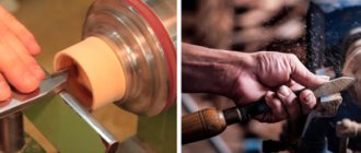
How to make a faceplate for a lathe chuck
When the assortment of stores does not suit the buyer, as well as in cases where the budget or time frame does not allow the purchase, homemade options are used. Of course, in order to produce such a product with your own hands, you must have the appropriate experience.
It is worth clarifying that we will be talking about a simplified design that is suitable only for basic parts. More complex options are not only problematic in production, but also have a very high cost, which means the event becomes expensive.
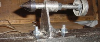
Creating a blank
- Initially, the necessary markings are applied to the timber. Using a compass, we mark the diameter, but it is better to take it with a margin of 2-3 mm, so that during further work, when you have to glue the parts, the size will not be smaller.
- Apply glue to the prepared elements. Press tightly and leave for 20 minutes.
- The next step is to create a metal washer. It is best to choose a size large enough for the nut so that it fits snugly and does not fall through. Sequentially weld it first from above, then from below.
- We install it on the spindle, and also select the grooves and holes. It is important to correctly determine the final task. Otherwise, it will not be possible to properly fasten the part. Please note that to install various devices such as a lathe vice, you must leave some space on the common surface. This means that you need to choose the appropriate plane size in advance.
- The last stage is the application of protective layers. Here the choice is obvious in favor of paint. It will not allow rust to appear on the outside. In addition, if you notice any unevenness during processing, it is quite possible to simply cut them down.
We tried to explain as fully as possible what a washer plan is, what it is needed for, and how its various variations are used. Most types can be purchased in the most convenient sets. It is not necessary to immediately take a large batch if there is no need for it. Kits that contain only one main drive and additional components for it are widespread.
Jig boring machines
The main feature of jig boring machines (Fig. 3) is the high precision of processing parts.
Figure 3. Jig boring machine.
Increased processing accuracy is achieved through the use of various high-precision mechanisms for calculating the coordinates along which the cutter moves. There are several main methods for calculating coordinates implemented on jig boring machines:
The spindle on the machines of this subgroup is located vertically. But sometimes there are models with a horizontal spindle. The spindle head, in addition to changing the speed and direction of rotation, also carries out a working feed, increasing or decreasing the depth of penetration of the cutter into the part.
The table has two degrees of freedom. A part fixed on a table can move in the longitudinal and transverse directions. Moreover, the magnitude of these movements is controlled with high accuracy by the coordinate system.
Also, on jig boring machines, in addition to performing the entire range of operations characteristic of boring group machines, marking operations are performed.
Can I do it myself?
With basic equipment and some lathe and engineer skills, home fabrication is possible. But the question remains about the necessity of such actions. After all, only the simplest variations can be made at home, and they are not difficult to find on sale, and they are cheap. But the economic feasibility of homemade equipment remains unproven.
Sometimes you need complex designs that cannot be found in stores. But usually their design is very complex, and manufacturing will take a lot of time.
However, if you decide to make it yourself, we will give some recommendations and show you how to do it.