How to make a pantograph for a router with your own hands? — Build Tool
Milling is a type of mechanical processing of materials using a special cutting tool - a milling cutter. The method allows you to obtain a high level of accuracy and the degree of roughness of the processed surface. In addition, it is distinguished by significant productivity.
Surface processing is carried out by the method of up milling, when the rotation of the cutting tool is opposite to the direction of feed, and by down milling - a method in which the direction of rotation of the cutter and feed are identical. By using cutters with cutting edges made from modern super-hard materials, the grinding operation can be replaced.
Milling equipment is divided into universal and specialized. In the first case, these are general-purpose machines for performing longitudinal and continuous milling, with or without tools mounted on a console. The second contains a mechanism for cutting threads, splines, making gears and keyways, and pattern milling.
In production, there is often a need to produce several pieces, a batch, or even a series of identical parts. For this purpose, milling equipment equipped with a pantograph is used.
In the household, the functions of a milling machine are usually performed by a manual milling machine. To perform the maximum range of work, the milling cutter is equipped with a whole set of accessories.
The main equipment is supplied with the equipment, additional equipment can be purchased or manufactured independently. These are a variety of stops, clamps, templates.
But you can go even further and make a copier for milling volumetric parts.
Milling and copying equipment: operating principle
The operating principle of such a device is to clearly transmit the movements of the copy head through the holder profile to the cutting tool.
It is quite difficult to purchase a copy milling machine, so craftsmen make it with their own hands from scrap materials. Everything happens by trial and error. Therefore, experts advise first assembling a duplicate carver, and only then introducing it into mass production. As a rule, this stage is preceded by more than one serious adjustment and alteration.
Milling and copying equipment: areas of application
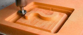
Milling copying machines can process not only flat, but also three-dimensional parts. With their help, along with simple milling operations, you can perform engraving, repeat drawings, patterns and inscriptions. The design of the machine is quite simple, and any craftsman can make it.
Copy-milling machines allow you to process not only wooden parts, but also cast iron, steel and plastic workpieces, as well as products made of non-ferrous metals.
This is ensured by high-quality tools made of high-speed steel and hard alloys. The copying machine allows you to mill not only straight, but also curved surfaces.
In this case, the details are completely identical.
Milling and copying equipment: design
The typical design of a copy-milling machine is completely simple. It consists of a work table and a guide system with clamps for attaching the router and copier.
Making a universal copy-milling machine at home is quite difficult, and there is no great need for it. For home use, equipment with highly specialized specialization is usually created.
Manufacturing of copy milling machine: materials
To create a duplicate carver at home with your own hands, you should draw a basic sketch, which will become a guide to further actions. In addition, you need to stock up on some materials. This:
- Knee cemented polished shaft Ø 16 mm.
- Linear bearings in the amount of 2 pcs.
- Rail guides 900 mm long – 2 pcs. For ease of fastening, their length is taken as a multiple of 150.
- Split linear bearings in the amount of 4 pcs. It is advisable to use bearings with a clamping screw to adjust the tightness of the fit on the guide.
- Profile pipe 30×60 with a wall thickness of up to 3 mm.
- Metal plate 900 mm long and 100 mm wide.
- End posts in the amount of 2 pcs.
- Moving element in the form of a plate – 1 pc.
- Rocker arm for attaching the copier and router – 2 pcs. The length is chosen arbitrarily.
- Movable couplings – 2 pcs.
- Profile pipe 40×40 with a wall thickness of up to 3 mm.
- Crown clutch for turning the part and template.
Making a copy-milling machine: tools
After this, you need to prepare a tool that will definitely be useful for assembling the machine structure. This:
- angle grinder;
- cutting and cleaning disc;
- welding machine;
- welding mask;
- petal disc or brush;
- self-tapping screws for fastening rail guides and moving elements;
- electric drill;
- screwdriver;
- measuring instruments: tape measure, caliper;
- center punch and scriber.
Making a copy-milling machine: step-by-step instructions
After everything is ready, the actual assembly of the copy-milling machine begins.
Step #1
It is necessary to cut two pieces 950 mm long from a 30×60 profile pipe to attach the rail guides. A margin of 50 mm is needed for installing limit switches in order to prevent linear bearings from slipping off.
Step #2
The 40×40 profile pipe needs to be cut into blanks for the base. Guided by the existing sketch, you need to cut two pieces of 1350 mm and two pieces of 900 mm.
Step #3
It is necessary to cut small racks from the same pipe. Their linear size depends on the height of the subsequently processed parts.
Step #4
Now you need to remove the rust from the pipes. To do this, you can use a flap disc or brush.
Important ! Before using the brush, pay attention to the maximum number of working revolutions on it and the grinder. The rotation speed on the brush must exceed the speed of the equipment.
After this, we weld all the joints and clean the seams with a 6 mm thick cleaning wheel.
Step #6
Then it is necessary to ensure parallelism of the rail guides. To do this, you need to make the connection between the rack and the base of the rail guide detachable.
It is necessary to take a washer according to the internal size of the rack, weld a nut to it and screw in the bolt.
At this stage, the bolt is needed in order to install the nut and washer in the cavity of the stand pipe flush and in a strictly vertical position, and when welding it, do not damage the thread. This must be done with all four racks.
Step #7
Weld the posts to the base.
Step #8
At the base of the rail guide, at the junction with the racks, you need to drill holes: in the upper shelf for the bolt head, in the lower one for the thread.
Step #9
Install the rail guides on the base (30×60 pipe), pre-drilling holes, and secure with metal screws.
Step #10
Install the bases with rail guides and tighten with bolts.
Step #11
Check the parallelism of the guides. If it is missing, it is necessary to make adjustments by placing foil of different thicknesses on the racks under the guide.
Step #12
On the metal plate you need to mark and drill holes for attaching split linear bearings and end posts.
Step #13
After this, you need to make a movable element by welding 300 mm long rocker arms for the feeler gauge and router to a metal plate, then attach linear bearings to it.
Step #14
After this, the moving element must be placed on a polished shaft, along the edges of which the end posts must be installed.
Step #15
The entire structure must be installed on a metal plate 100 mm wide and the end posts must be secured with self-tapping screws.
Step #16
Then, split linear bearings must be installed on the metal plate on the bottom side.
Step #17
After this, the suspended structure is put on the rail guides with split bearings and the end switches are installed.
Step #18
Movable couplings are installed at the end of the rocker arms and a probe and a milling cutter are attached.
Step #19
In order for the workpiece and the part to rotate synchronously, it is necessary to connect them with couplings. A sprocket and crown are suitable for control. The copy milling machine is ready.
The design achieved 5 degrees of freedom.
Movement along the X axis is ensured by the movement of the structure along rail guides, movement along the Y axis is ensured by the movement of a moving element along a polished shaft, and movement along the Z axis is ensured by the movement of rocker arms.
Additionally, due to the movable couplings, the probe and the milling cutter can move left and right along the axis of the rocker arm, and it is possible to move the template and the workpiece simultaneously. This makes it possible to process parts of almost any shape.
Copy-milling machines for metal in mass and serial production
Metal copying and milling machines are used in mass production. With their help, ridge propellers for ships, jet engine turbines, pump impellers, dies for forging and press production, and blanks for mechanical and foundry production are manufactured. In everyday life, metal copying equipment is practically not used.
Pantograph for a router: design features
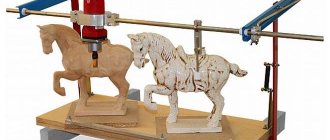
To scale copying processes, there is a special device called a pantograph. It facilitates the manufacturing processes of parts with curved surfaces and allows you to produce ornaments and patterns of any complexity in a reduced form. The cost of such a device is quite high. But making a pantograph at home with your own hands is quite possible.
Pantograph for a router: principle of operation
The schematic diagram of a pantograph looks quite simple. It is a square divided in half. All joints are hinged, so all sides are movable, and the square easily turns into a rhombus when impacted. The zero point, located in one of the corners of the square, is fixed rigidly.
Relatively, its design can be modified, turning into a rhombus. A cutting tool is installed in the middle of the square. A copier is fixed diagonally in the opposite corner of the square. The distance from the zero point to the cutter is a certain value A, and to the copier 2A. This gives a 2:1 scale.
The linear size of the long and short sides of the pantograph should also differ from each other by 2 times.
Pantograph for a router: materials
In order to make a pantograph with your own hands, you will need the following materials:
- Square metal profile 12×12
- Bearing 180201.
- Bushings for the outer race of the bearing.
- Pins according to the internal size of the bearing and M12 thread.
- Nut M12.
- Bolts M6×45
- Nuts M6.
- Bushing for securing the copier.
- Profile pipe 40×40
- Hinge of a metal-plastic window.
- Dye.
- Masking tape.
- Metal plate.
- Screw for fixing the copier.
Pantograph for router: tool
In addition to the materials listed, you will need the following tools:
- Manual frezer.
- Angle grinder.
- Welding machine.
- Spanners.
- Measuring tool.
Pantograph for a router: step-by-step instructions for making it yourself
Let's proceed to the actual production of the pantograph.
Stage No. 1. Workpiece cutting
It is necessary to mark and cut the square profile according to the calculated dimensions. For convenience, you can use masking tape and a metal plate.
The tape will allow for clear markings, and the plate will help make an even and high-quality cut.
The blanks for the platform for the router must be cut at a right angle, and the sections of the profile for the connecting rods must be beveled for maximum fit of the bearing sleeve.
Stage No. 2. Drilling technological holes
All workpieces must be chamfered and holes Ø 6.2 mm drilled for further connection into the structure.
Stage No. 3. Welding the platform for the router
After this, you need to weld the platform for the router.
Stage No. 4. Manufacturing of connecting rods
It is necessary to make something like a jig on the board and firmly fasten all the parts to be welded. To do this, a hole is drilled in the board, and the bearing in the bushing is clamped with a bolt, the square profiles of the connecting rods are secured with clamps. First you need to insert two washers between them and fasten them with bolts.
Furniture
The next version of the concept under consideration is also universal. It is used in various furniture. A clothing pantograph is a closet fixture. It began to appear especially often with the advent of sliding wardrobes.
Of course, it is not immediately clear what we are talking about. Only those who have acquired high closets, from where it is difficult to get clothes, can guess. So, in this case, the pantograph is a U-shaped device that helps you reach dresses and suits with one movement.
In addition, this mechanism is often used to save space. This is especially important when buying or ordering a cabinet for a small room, where every centimeter is worth its weight in gold.
The advantage of this device is that you can very quickly get things out of the depths of the closet by lowering the bar to eye level. Hangers with seasonal dresses and suits change so quickly. Special lighting can be provided with the pantograph. It all depends on the size of the furniture.
How to make a pantograph with your own hands
All photos from the article
Wood copying and milling machines are universal units whose purpose is to copy products in two- and three-dimensional form. In other words, this equipment can copy flat finished products, and when using special copiers, also three-dimensional models.
Such devices are often used for engraving profiles and various decorative elements. They can also be used for ordinary, not very complex milling work.
With a fairly simple design, such units are capable of reproducing very complex wood products.
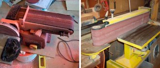
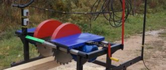
Unit design
The photo shows a desktop device with mechanical clamps.
Copy-milling units make it possible to process reliefs or profiles:
- The workpieces are processed with a special tool - a milling cutter made of hard alloys.
- It repeats in full the movements of the copier, which reproduces the outlines of the template.
- The copier is equipped with an electronic or mechanical connection that has a tracking system and is responsible for the trajectory of the tool.
- The copier can be a flat or three-dimensional sample, as well as a contour diagram or a reference model.
- In this case, a special probe registers the contours of the part. This data is then reported to the tool.
- In the most modern machines, the probe is replaced by a photocell, which has increased accuracy.
Note! The pantograph plays a vital role in the described units. It is equipped with a special guide “finger”.
It moves along the copier, while determining the geometric parameters of the sample with maximum accuracy. The final size of the resulting copy depends on the proportions of the pantograph’s “shoulders.”
Device
So, let's start with the most explicit definition for the term being reviewed. A pantograph is a tool for redrawing plans, maps, and large diagrams on a smaller scale.
This device may vary. It all depends on the requirements and purpose. There are options with wheels or hanging structures. One of the vertices of the tool moves in a straight line.
DIY pantograph drawings
Milling is a type of mechanical processing of materials using a special cutting tool - a milling cutter. The method allows you to obtain a high level of accuracy and the degree of roughness of the processed surface. In addition, it is distinguished by significant productivity.
Surface processing is carried out by the method of up milling, when the rotation of the cutting tool is opposite to the direction of feed, and by down milling - a method in which the direction of rotation of the cutter and feed are identical. By using cutters with cutting edges made from modern super-hard materials, the grinding operation can be replaced.
Milling equipment is divided into universal and specialized. In the first case, these are general-purpose machines for performing longitudinal and continuous milling, with or without tools mounted on a console. The second contains a mechanism for cutting threads, splines, making gears and keyways, and pattern milling.
In production, there is often a need to produce several pieces, a batch, or even a series of identical parts. For this purpose, milling equipment equipped with a pantograph is used.
In the household, the functions of a milling machine are usually performed by a manual milling machine. To perform the maximum range of work, the milling cutter is equipped with a whole set of accessories.
The main equipment is supplied with the equipment, additional equipment can be purchased or manufactured independently. These are a variety of stops, clamps, templates.
But you can go even further and make a copier for milling volumetric parts.
Step #5
After this, we weld all the joints and clean the seams with a 6 mm thick cleaning wheel.
Stage No. 5. Making a unit for attaching a copier
Now you need to machine two bushings with an internal diameter similar to the size of the copier. Drill a hole on the side and cut a thread to install the screw that secures the copier. After this, you need to cut two pieces of 12x12 squares 20-30 mm long and weld them on the side between the bushings. The size between squares should be 12 mm.
Stage No. 6. Manufacturing of the bearing lifting mechanism
It is necessary to manufacture a bearing lifting unit. To do this, the zero point finger must be welded onto a piece of 12×12 profile and secured to a 40×40 profile pipe using a loop from a metal-plastic window. The profile pipe will serve as a place for attaching the pantograph to the table with a clamp.
Stage No. 7. Pantograph assembly
The bearings must be installed in the bushings and secured securely by tightening the square profiles of the connecting rods with M6 bolts. Using your fingers, you need to assemble the connecting rods into a single structure. Secure the pantograph to the table with a clamp and install the router. The device is ready for use.
Cutting tools for milling work: copy cutters
Copy cutters are a tool on which, in addition to the cutting part, there is a bearing. Its size is equal to the diameter of the cutting part of the cutter. The bearing can be located both in the upper and lower parts of the cutter. This is how the tool is classified. It is worth considering that the marking indicates the position of the bearing in the usual placement of the cutter - with the shank up.
They are used to perform copying work according to a template. When using a cutter with an upper bearing, the template is located on top of the part; if with a lower bearing position, then from the bottom.
Working with a hand router involves the use of any cutters. It is safe. The only thing is that when using a cutting tool with an upper bearing, you should pay attention to the overhang of the cutter so as not to damage the workbench.
Milling on a woodworking machine involves using cutters only with a lower bearing position.
This is due to the fact that a cutter with an upper bearing position has an open rotating cutting part in the workpiece area. Careless movement may result in serious injury.
Such cutters are used on machines only in special cases with maximum compliance with safety regulations.
Copy-milling machines are unique equipment with the help of which the most complex work is performed on the production of identical parts. But for working at home, you can make simple analogues of such equipment and devices that will help in your home or small business.
CNC on muscular traction (3D Pantograph)
In the modern world, in the community of people who love to do things with their own hands and who do not shy away from technology, such a thing as a desktop CNC machine is extremely popular. Although these devices have become quite accessible, they still remain expensive.
The cheapest Chinese option today will cost you 700-800 US money and it will probably not work right out of the box, but will require some effort to bring it to fruition.
Making a CNC machine yourself can be cheaper, but usually requires access to various types of woodworking and metalworking equipment and the ability to use it to produce parts with high precision. But people are always looking for ways to achieve the goal with affordable means.
In some tasks for CNC machines, namely when you need to repeat the same part many times, a pantograph, invented back in 1603 by Christoph Scheiner, can help - a device for copying maps, plans and other vector drawings.
Ancestor
Like many other objects, the pantograph has a “parent”. It was Christophe Scheiner. He was a German astronomer, physicist, mathematician and mechanic. At one time he joined the Jesuit Order.
Initially, Sheiner became famous in astronomy, and then in other sciences. He became the inventor of many useful devices. For example, he worked on a telescope with two convex glasses, based on Kepler's developments. He also created two drawing tools: a device for drawing conic sections and a pantograph. This discovery was largely fundamental for the development of other similar mechanisms.
How to make a pantograph with your own hands - Metalworker's Guide
A milling cutter equipped with a pantograph allows you to repeat parallel lines of the workpiece during work.
This procedure facilitates the production of shaped parts, various ornaments and patterns.
In addition, using a pantograph you can make various inscriptions on metal and wooden plates.
It’s not difficult to make a homemade pantograph; you just need 4 ruler levers. Three such levers should be long, and one should be short. In addition, you will need to make several holes in them to mount the axles.
The axles will be used to install the mechanism and attach the rod. The axial mechanism is a pin with a cap at the end.
The copying part should resemble a compass element in which the stylus is attached. Such a rod part can be made from the tip of a plastic knitting needle.
Such a tip will glide gently during operation and will not damage the original part.
You will also need an axis on which the entire mechanical part of the device will rest. It must be equipped with a heel that acts as a stop. The last or outer guide will act as a fastener for the entire structure using a special boss.
Such a boss should be made of an aluminum cylinder. In its lower part you need to attach 3 stings, which can be made from small furniture nails. These nails will be used to secure the base to the plate being processed.
Completion of work
The next step is to assemble the copying mechanism for the router. To do this, you need to prepare the following components:
- 4 rulers;
- 8 brass bushings.
Rulers should be made of plexiglass or plastic, their thickness should be 4-5 mm. You can also use plexiglass as a material for making rulers.
Next, the marking of these linear parts is carried out.
This process should be approached very carefully, since the slightest error in dimensions can lead to incorrect operation of the pantograph.
Holes are drilled on the marked markings. In this case, their alignment must be maintained. To achieve this, you need to put all the rulers together and drill holes in them at the same time.
Then you need to insert brass bushings into the prepared holes. When installing them, a slight tension should be observed: this will help the bushings to stay more tightly in the rulers.
In order to secure the axial parts in the bushings, you need to make special clamps.
They can be made from hardened steel wire, the diameter of which should be 1-1.5 mm.
Then the boss is assembled. Blind holes are made in its lower part, which can be punched with a core. The nails must be installed in such a way that they protrude from the body of the boss by 2-3 mm.
Having prepared all the necessary parts of the pantograph, they are assembled.
During this process, you need to ensure that all moving parts move smoothly and easily.
In this case, all prepared holes should be marked. According to this marking, you can scale the manufactured copy of the part.
moiinstrumenty.ru
Make it for school
Pantograph
This simple drawing device can be used to redraw plans, drawings, geographical maps or decorative elements, increasing or decreasing their scale by 1.5, 2 and 3 times.
The device is a parallelogram formed by four planks - two long and two short, made of well-planed hardwood (oak, beech or birch).
The planks are connected to each other with screws and nuts. Pay attention to the screw (view B) - it is of an unusual type.
If the device is used to obtain a copy on an enlarged scale, a guide pin is fixed in node B - it can be a blunt nail clamped into a collet pencil, and a regular pencil, felt-tip pen or ballpoint pen is fixed in node B.
By tracing the lines of the original with a pin, we will obtain a copy of the specified magnification scale on paper. To obtain a copy in a reduced form, the guide pin and the writing instrument are swapped.
To select the scale, holes are provided in the long and short bars and a digital designation is entered, the ratio of reduction or increase.
Clamping pins are most easily made from a piece of rubber in the form of flat washers. The holes in the washers should be cut so that the collet pencil and writing instrument fit tightly into it.
A clamp is provided to secure the device to the workbench. It must be made from a steel plate 1.5 mm thick.
To prevent the clamp from scratching the table top, cut a 2 mm thick rubber gasket under it. There is a hole on the upper plane of the clamp into which the pantograph axis is inserted.
As you can see, there is no bearing here. Therefore, to reduce friction between parts, install washers.
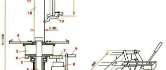
A. SALNIKOV
In the figure, the numbers indicate: 1 - clamp, 2 - rubber gasket, 3 - table cover, 4 - long strap, 5 - short strip and 6 - rubber clamps.
12
zhurnalko.net
Usage
On electric locomotives with several pantographs, not all are used at the same time. Usually the last one rises along the route of transport. If icing of the contacts is noticeable, then all mechanisms can be raised for safety.
Powerful electric locomotives that use direct current and have several pantographs use the last two when moving. There is a theory that this use of mechanisms is related to safety.
In situations where a breakdown occurs and the pantograph falls, it can damage important control mechanisms. If the last two are used, they may simply collapse on the track, or on the roof of an unused control cabin.
Also, operating a pantograph in this way is due to the fact that the driver, having noticed a fault in the contact network ahead, may not have time to lower the front mechanism.
Well, the last option is related to physics. As the vehicle moves, it creates an air compression zone. It raises the contact wire, which means the contact conditions for the front pantograph are the worst.
One Reply to “Pantograph for router”
Comments are closed.
- All in all
- Workshop
- Furniture In the bathhouse
- To the living room
- To the nursery
- To the office
- To the kitchen
- To the bedroom
- Soft
- Sadovaya
- Garlic
- Chickens
- Toys
- Finishing
- Drill
- Materials
Tags
Recent Entries
- Tool breakdowns, search for spare parts and self-repair
- Wood in the interior: warm and cozy
- What is an edge router?
- Milling cutters PIT PER12-C, Diold MEF-2.1, VORTEX FM-1900, STERN Austria ER2050 – twins and brothers?
- Review of the Festool OF 1400 hand router. Is it worth the money?
Recent comments
- Ratmir on How to make a jointer from an electric planer
- Tool breakdowns, search for spare parts and self-repair to the entry Milling cutters PIT PER12-C, Diold MEF-2.1, VORTEX FM-1900, STERN Austria ER2050 - twins and brothers?
- Wood in the interior: warm and cozy to the post Do-it-yourself children's table made of solid wood
- Review of the Festool OF 1400 hand router. Is it worth the money? back to entry Device for milling sockets and grooves
- Slot milling attachment for recording Festool OF 1400 manual router review. Is it worth the money?
How we build a house
Attention! 15% discount on repair items. Using promo code GD181215REM. Applies to power tools, measuring equipment, pneumatic tools, power equipment, machine tools, hand tools, construction equipment and supplies, electrical installation products.
Making a copy-milling machine: tools
After this, you need to prepare a tool that will definitely be useful for assembling the machine structure. This:
- angle grinder;
- cutting and cleaning disc;
- welding machine;
- welding mask;
- petal disc or brush;
- self-tapping screws for fastening rail guides and moving elements;
- electric drill;
- screwdriver;
- measuring instruments: tape measure, caliper;
- center punch and scriber.
Installation and operation rules
Homemade drilling and adding machine for furniture production
The pantograph is mounted on the sides of the cabinet, on laminated chipboard. Before installation, you should be careful about self-tapping screws. Their length should not exceed 16 mm. The kit often includes slightly longer screws. They can go through the closet wall, which looks unsightly.
Mechanical options are installed in a similar way, except that they do not need to be connected to the network.
Some models are mounted directly on the wall. They are intended for dressing rooms.
Installation steps for an electric pantograph, which is activated by a button:
- unpack, check how it works, connect to the network;
- measure the distance from the outlet; it should be enough to connect the device;
- take clothes out of the compartment, try on the mechanism, make notes for installing fasteners (in the absence of documentation, measurements are carried out manually);
- drill holes at the fastening points;
- install the frame into the grooves.
The pantograph will work immediately after connecting to the network. Control is carried out using a button or pedal. The hanger rises and falls in just a couple of seconds after pressing.
Most pantographs have a rod clearly in the middle to evenly distribute the center of gravity.
Mechanical pantographs are installed in a similar way. The only difference is that there is no need to connect the mechanism to an outlet.
During operation, maximum loads should be avoided. The mechanism wears out quickly, so sudden movements should be avoided. When lifting an empty pantograph, the handle must be held with your hand, which will avoid inertial movement of the structure until it crashes into the wall. The presence of clothing will slow down the sharp movement of the mechanism, the handle will also slow down on the clothing. The mechanism does not require special care; careful operation will help to avoid malfunctions.
It is very easy to get any item from your wardrobe if you have a pantograph. Take advantage of modern solutions.
Milling and copying equipment: areas of application
Milling copying machines can process not only flat, but also three-dimensional parts. With their help, along with simple milling operations, you can perform engraving, repeat drawings, patterns and inscriptions. The design of the machine is quite simple, and any craftsman can make it.
Copy-milling machines allow you to process not only wooden parts, but also cast iron, steel and plastic workpieces, as well as products made of non-ferrous metals. This is ensured by high-quality tools made of high-speed steel and hard alloys. The copying machine allows you to mill not only straight, but also curved surfaces. In this case, the details are completely identical.
Advantages and disadvantages
In most cases, a pantograph helps improve the quality of life. But it also has disadvantages.
Advantages:
- makes it easier to find, get and hang things in the closet;
- improves ventilation: clothes are fresher;
- makes it easier for older people and people with disabilities to get things;
- frees up the lower part of the cabinet for additional shelves;
- reduces the need for ironing: you can hang more clothes than in a regular closet.
Judging by the reviews, breakdowns occur on average after 3-4 years.
The main disadvantage is wear and tear over time. Gradually, backlashes form between the structural parts, which disables the entire mechanism.
It is almost impossible to repair individual parts of the pantograph; the entire system has to be replaced.
This design is inferior to a conventional horizontal hanger bar, which can last forever
Another drawback is the possible creaking of parts during operation. This becomes a problem if the closet is located in a shared bedroom. Compared to a regular bar, pantographs are significantly more expensive and require more complex installation.
Manufacturing of copy milling machine: materials
To create a duplicate carver at home with your own hands, you should draw a basic sketch, which will become a guide to further actions. In addition, you need to stock up on some materials. This:
- Knee cemented polished shaft Ø 16 mm.
- Linear bearings in the amount of 2 pcs.
- Rail guides 900 mm long – 2 pcs. For ease of fastening, their length is taken as a multiple of 150.
- Split linear bearings in the amount of 4 pcs. It is advisable to use bearings with a clamping screw to adjust the tightness of the fit on the guide.
- Profile pipe 30×60 with a wall thickness of up to 3 mm.
- Metal plate 900 mm long and 100 mm wide.
- End posts in the amount of 2 pcs.
- Moving element in the form of a plate – 1 pc.
- Rocker arm for attaching the copier and router – 2 pcs. The length is chosen arbitrarily.
- Movable couplings – 2 pcs.
- Profile pipe 40×40 with a wall thickness of up to 3 mm.
- Crown clutch for turning the part and template.
Personal assembly of equipment at home
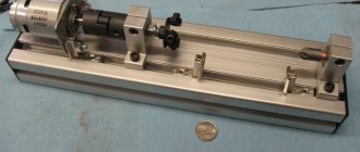
Lathe
In order to assemble a small copying machine for wood with your own hands, you will need to make some effort and patience, as well as invest financially (about 7-7.5 thousand rubles). But this is several times less than the costs that await you if you purchase a ready-made option.
These are the masterpieces of interaction between hands and head found in private workshops
The model of small-sized equipment of the so-called beam type proposed for assembly can be divided into the following components:
- Frame.
- Slave and leading center.
- Electric motor.
- Front and rear headstock.
- Stop for cutter.
Now we’ll tell you in more detail about how a wood copying lathe looks and is assembled:
It is clear that the frame is the foundation of the entire structure, on which all other parts will be based. Therefore, appropriate requirements are placed on it. It must be strong, stable and reliable. Therefore, it is better to make it from a steel profile, but a wooden beam with a large cross-section is also quite suitable. The electric motor and the driving center are connected to each other and fixed to the front of the base. Due to the electric drive, the blank is rotated.
Another option where the sampling depth depends on physical strength (pressing the handle, in the photo)
- The headstock serves as a stop for the workpiece, so it is permanently attached to the frame.
- By moving the tailstock along the frame, the workpiece will be transformed into a part of a given sample.
- A stop for the cutter is installed between the tailstock and the front headstock, which will serve as a holder.
- The tailstock and front headstock and the stop for the cutter are mounted clearly along one line.
- All components of the machine must be securely fastened with bolts.
Fasteners should be chosen only new, galvanized, tightening all individual elements with force so that the connection does not come loose. And wood turning and copying machines should be installed only level to avoid the slightest vibration.
Milling machine
If you wish, you can also assemble a homemade copy milling machine for wood with your own hands.
Such a device is capable of:
- Planar milling for creating profiles.
- Volumetric milling for the design of reliefs.
A copying cutter for wood made of carbide metal reproduces the surface or contour of the master copier on the product.
The following is used as a copier:
- Spatial model.
- Flat template.
- Reference model.
- Outline drawing.
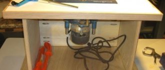
The simplest milling copier consists of a supporting frame - a base, a work table and directly a milling head equipped with an electric drive.
A hole is made in the center of the board and a router is attached in place of the hole, only on the reverse side
- The dimensions of the workbench depend on the specific tasks for which the copy milling machine is assembled, as well as on the dimensions of the workroom.
- Based on the nature of the work and the dimensions of future products, methods for fastening the workpieces and template are determined.
- The power of the electric motor that rotates the cutter is also selected taking into account the planned loads.
Thus, having a copy-milling machine for wood in your workshop, you can create copies of the parts necessary for repairing furniture and other wooden structures with your own hands. You can also make souvenir or decorative items according to your own drawings.
Since work on such equipment is quite dusty, it is best to place the machine outside or under a hood
Story
The ancient Greek engineer Hero of Alexandria described pantographs in his work Mechanics.[1]
In 1603[2] Christoph Scheiner used a pantograph to copy and scale diagrams and wrote about the invention more than 27 years later in Pantographics.
(Rome 1631).[3]One arm of the pantograph contained a small pointer and the other a drawing instrument, and by moving the pointer across the diagram a copy of the diagram was drawn on another sheet of paper.
By changing the positions of the arms at the junction between the pointer arrow and the drawing hand, you can change the scale of the image created. Diagram illustrating the principles used by the William Wallace Eidograph
In 1821, Professor William Wallace (1768–1843) invented the Eidograph to improve the practical utility of the pantograph.[4] The eidograph moves a fixed point to the center of the parallelogram and uses a narrow parallelogram to provide improved mechanical advantages.
Examples of manufacturers
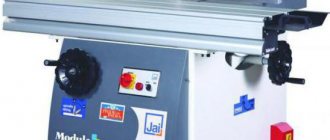
Those who need a reliable machine for flat milling should pay attention to the products of the Italian company GRIGGIO. Machines of this brand have a relatively low price and are a good solution for creating shaped parts, skirting boards, and trims
With their help it is convenient to create facades of furniture panels and wooden doors.
The VFK-810 milling machine with a table rotation angle of 45 degrees is perfect for those who are interested in making furniture. Its distinctive feature is the high speed of rotation of the cutter (up to 20,000 rpm), which guarantees excellent surface quality of the finished product.
The Chinese MX 5068 unit has comparable characteristics at a much lower price. It boasts a cutter rotation speed of up to 18,000 rpm and uses a pneumatic drive for table rotation and tool movement.
Those who are planning to take up carpentry seriously should pay attention to a milling unit made in Taiwan. WINNER LH-1000 will be the best assistant when it is necessary to mass produce similar parts
A special feature of the machine is a multi-level spindle, which allows you to perform several operations at once in one pass and create a product of the required profile without the need to rearrange the cutting tool.
Other options
If you understand the operating principle of any of the pantographs described above, you can probably find a couple more options for such a device. For example, sofas have a kind of Tic-Tac mechanism. It is also called a pantograph.
This mechanism for unfolding the sofa will protect the parquet from scratches, as well as from marks of wheels or feet on the carpet. There are many similar transformations. When using this mechanism, the vertical back of the sofa acquires a horizontal position, and its second part is neatly lowered to the floor.
Another example of such a device would be a pantograph for a microphone. If you've been to a studio, you've probably seen stands for devices that can be raised, lowered, and moved in different directions. They also resemble the mechanism of some table lamps that are attached to the table.