The article describes in detail how to make a wood milling machine with your own hands with all the details of the working platform - bed, tabletop, base plate, additional protective devices. Step-by-step technologies for converting a drill and washing machine engine into a milling machine are presented, as well as the main points of manufacturing a machine with numerical control.
Preparing to make a milling machine
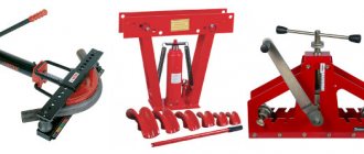
When planning to make a wood router with your own hands, you should proceed from the basic principle. It is better to immediately install the cutting attachment of the machine so that it can process wooden workpieces not only along straight contours, but also along curves. This will be needed for shaped sharpening of edges and making complex grooves. The type of router depends on the tasks being solved.
- For figure cutting, a manual milling machine with a movable cutter, which is attached to a spindle fixed to the shaft, is suitable. The movement of the cutter is provided by a motor placed in the housing.
- Plunge-type milling machines are used to make holes of the required depth.
Plunge router
- A stationary milling machine will allow you to obtain a more complex recess and pattern on a wooden workpiece. In addition, work time is saved compared to hand tools.
Important! For periodic processing of workpieces in small quantities, a manual milling machine is sufficient, but it is better to entrust regular work with large batches of lumber to a stationary tool.
Necessary materials:
- washing machine motor;
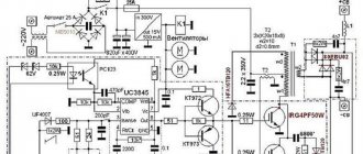
- electrical board for speed control;
- car speedometer cable;
- wire with switch;
- drill chuck;
- a piece of OSB or plywood;
- wooden slats 40x20;
- a piece of HDPE pipe with a diameter of 25 mm.
Required tool:
- jigsaw or saw;
- screwdriver;
- measuring tool;
- drill.
The process of making a drill.
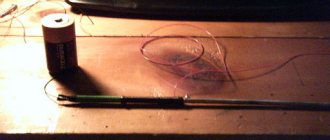
First of all, for work you will need a cable from the car's speedometer. It is necessary to cut off the fittings at the ends of the cable so that its ends are visible
The next step is to move on to the motor from the washing machine. In my case, the most ordinary engine, it has a marking plate like this
Next, you need to drill a hole about 1.5 cm deep on the motor shaft. The pulley will not interfere, so I will not remove it
and then into this hole I glue one end of the cable with good epoxy glue
Now you need to make a base for the engine and secure it. Everything is very simple here, I cut the slats, drilled holes in them, secured the engine to them with pins, and secured the slats to a piece of OSB. This is how it all worked out for me
Next you need to make a stop for the cable. To do this, I drill a hole in a section of a wooden block, and then cut it with a jigsaw to make half the hole and attach the cable
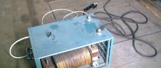
Next, I connect all the electronic components. At first glance it may seem difficult, but it is not. I ordered the board in China, it is specially made for such motors and connects without problems. This is how it all looks for me
I installed a magnet on the shaft and attached a hall sensor next to it on a piece of aluminum corner to operate the tachometer
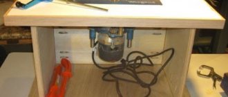
The next step was to assemble a simple case. I cut a hole opposite the board and installed a ventilation grille.
At this point, the assembly of the power part of the drill is ready, let’s move on to the second part, namely the assembly of the working unit. I'll need an old drill chuck
I drill a hole in the center to a depth of 1.5 cm
Well, then I clamp the chuck into the drill and, using a grinder, reduce the diameter of the chuck shaft, thereby adjusting it to the inner diameter of the bearings
Next, I put on the bearings and solder the second end of the cable
As a handle I will use a piece of HDPE pipe, which I cut lengthwise and then put on the bearings
To make the pipe fit tightly, I tied it with blue electrical tape
The drill is completely ready, this is what it looks like
It has an impressive margin of safety, smooth speed control, without loss of power and reverse.
In the video you can familiarize yourself in detail with the manufacturing process and watch a demonstration of the drill in operation.
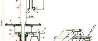
General arrangement of a workplace for a milling machine
The working platform for milling typically consists of the following structural elements:
- bed;
- Workbench;
- table top;
- machine frame;
- drive support platform;
- directly milling machine;
- spindle for securing the cutter;
- spindle launch panel;
- slides that ensure the movement of the workpiece;
- management control system.
General arrangement of the workplace
Connection and launch
When dismantling the electric motor from the washing unit, it is recommended to make special marks on all its wires. These steps will help you connect the motor directly to the electrical network in the future (this is especially true for asynchronous electric motors from old washing units, which require connecting starting capacitors). Other types of motors also have their own characteristics.
Therefore, to correctly connect each type of electric motor, it is best to search for information on the Internet or use special reference books for this. And if during dismantling all contacts were marked, then starting the motor from the washing device will not be difficult. To do this, you just need to follow the instructions for connecting a certain type of engine to the network and adhere to safety rules.
First of all, to make a generator, you need to remove the rotor from the working electric motor from the washing machine.
The anchor needs to be ground down, reducing its diameter. This can be done by clamping its shaft in a drilling machine and grinding the core with a grinder with a flap wheel. This is even easier to do on a lathe.
On the machined anchor you need to install 8 rows of 2 neodymium magnets. The polarity of adjacent pairs must alternate.
Now you need to fix the magnets with resin. To do this, formwork is assembled at the anchor from a CD and a piece of plastic pipe. It can be glued with hot glue. Then resin is poured into it.
Creating a mold for pouring epoxy resin
After the resin has hardened, the formwork is cut off. Then you grind the anchor to balance it. As a result, it should fit into the motor stator without any problems.
The engine is reassembled with the rotor already modified. Now you need to determine its working winding with a multimeter, since 220V can be removed from it when spinning up the generator. In this case it is the yellow and red wire. The blue core of the starting winding is not needed.
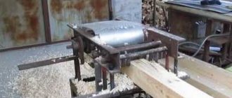
Mountings are welded to the generator. It is then screwed to the board. You need to attach a gasoline engine to the side; you can install a motor from a brush cutter.
You need to install a pulley on the generator shaft and the motor shaft and put on a belt.
Now, when starting a gasoline engine, it will spin up the generator, which allows you to receive 220V. The frequency of the current is not as stable as in a regular network, so it is better not to connect sensitive electrical appliances to it without a voltage regulator. However, such a generator is capable of powering construction power tools, a water pump, lighting lamps, etc.
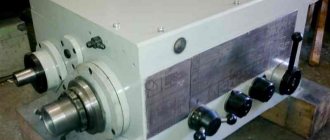
Engine requirements for a milling machine
The main parameter of the electric motor for the future router is power. It is recommended to install the motor at 1100-1200 W. For simple wood processing, 400 W is enough, but higher power will allow you to work with different types of cutting attachments, that is, expand the capabilities of the tool. A three-phase asynchronous motor from a drill, hammer drill, or grinder is suitable.
Three-phase asynchronous motor
Engine speed from 10 to 35 thousand rpm. Insufficient frequency will lead to poor sharpening; excessive frequency can lead to overheating and even fire of the wooden workpiece.
As for power supply, homemade home routers are connected via a standard 220 V network. It is worth equipping the machine with a power cable with a cross-section sufficient for the engine power.
Important! It is recommended to equip the milling machine with a switch for soft start and quick stop modes. The motor is designed so that the motor brushes can be changed without disassembling the housing.
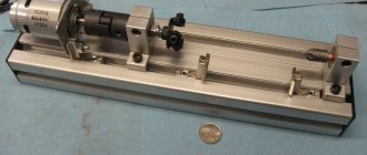
Moving parts
Having finished connecting the engine and making sure that it normally increases and decreases speed, you can proceed directly to the circular device.
Let's figure out which moving units that bear the main load we will need:
- saw shaft,
- SMA motor shaft,
- drive belt,
- two pulleys - from the washing machine and the circular shaft.
The drive must operate in this manner. The engine transmits rotation to a shaft on which a small pulley is pressed. The last one is wearing a belt that sends revolutions to the second pulley. At first glance, everything seems simple, but when the circular is being installed, many difficulties arise that must be resolved.
The small pulley must be sharpened. Three to four transverse grooves are placed on it so that the belt has the opportunity for a good hook.
You don’t have to use the belt from an old washing machine; just take an analogue from another unit. The main thing is that it is durable and has teeth.
A disc of a slightly larger diameter is welded to the edge of the large pulley to create a protrusion that prevents the belt from slipping during operation. It is not necessary to sharpen the serrations on this pulley; the clutch with the belt will be quite sufficient.
The shaft holding the circular saw, fastenings in the form of a washer and a nut must be reliable so that at maximum speed the saw does not become deformed and does not jump off, injuring workers. It is recommended to use the shaft and fasteners from a factory-made circular saw.
The procedure for constructing a circular saw is described for a saw with a three-hundredth blade. Many will say that the SMA engine will not pull such a saw and will stop. But here you should remember a few rules:
- you need to be able to work correctly on a circular saw,
- household saw, designed to work with small volumes of materials,
- the successful operation of such a saw is confirmed by numerous reviews.
Simply put, the saw should not be overloaded, and it is better not to work at idle speed .
Step-by-step procedure for assembling a working platform for a wood milling machine
The standard sequence of stages for making a working platform for a wood router with your own hands:
- Construction of the bed.
- Installation of workbench and tabletop.
- Drilling a hole for the base plate to drive the router.
- Manufacturing of one side and two comb stops.
- Connecting the dust collector to the vacuum cleaner.
- Additional protective elements
- Installing the wood router into working position.
- Connecting to the network, checking operation.
Milling table bed
The first thing to construct is the frame - a frame for the milling table. It is made of metal or wood, depending on the material and dimensions of the future workpieces. Type of construction: prefabricated or cast. The primary requirement for the bed is high stability while working with a router.
The metal frame is designed as follows:
- Using a grinder, pieces of corner profiles or pipes of the required length are cut and welded together.
- At a height of 15-20 cm from the floor or other supporting surface, transverse jumpers are welded for greater stability.
- Support plates are welded to the upper ends of the vertical pipes.
- Threaded holes are made in the plates for bolts to fix the future table.
Idea! Instead of a profile, you can use adjustable supports. This will allow you to install a bed for a homemade router even on a not-so-even surface.
Stand with adjustable legs
Milling table
The entire milling process is carried out on a special table, better known as a workbench. Its dimensions depend, first of all, on the area of the workshop, and secondly, on the volume of work. There are three types of workbenches for a milling machine:
- Static – installed in one place as a full-fledged working platform;
- Portable - a table that is easy to assemble and disassemble, which can be taken for on-site milling operations;
- Aggregate – used in spacious rooms.
A portable milling workbench, despite being easy to transport, is only suitable for processing small parts. It is recommended to work with a static table.
Tabletop for router
To make a tabletop for a router, as a rule, dense laminated plywood with a thickness of at least 1 cm is used. Another option is a 2.5 cm sheet of chipboard with polymer protection on top and at the ends. The protective layer, in addition to its direct function, also reduces vibrations during operation. Recesses are drilled into the sheet into which metal profiles are placed.
A used countertop from a kitchen set will do, as long as it does not have the slightest irregularities, nicks, or distortions. This will not only create unnecessary vibrations, affecting the quality of the milling, but can also damage the cutting attachment of the router.
Drive base plate
A rectangular opening is drilled in the center of the tabletop into which the base plate for driving the router will be mounted. To make the machine vibrate less during operation, it is recommended to make the recess round. The main thing is to make sure that the stove and the motor do not come into contact with each other. There should be a gap of at least 1 mm.
Drive opening
The base plate is made from at least 5 glued plywood sheets, but more often from textolite with a density of at least 1.5 cm. The plywood should first be treated with a vibration-absorbing agent. The milling machine is attached to the base plate with long motor bolts, onto which washers with rubber gaskets are additionally placed. Thanks to this, the cutting attachment will move up and down.
Side stop
It is also necessary to make a static side stop with a dust collector socket. Material - a sheet of plywood with a thickness of at least 2 cm. 3-5 holes are drilled in the table for the comb and lifting stop. The first 2 holes should be made at a distance of 0.5 cm from the edges of the rectangular recess for the cutter, the next ones - 2.5-3 cm from the first. The position of the stops depends on the size and quality of the workpiece material. To regulate the slight lateral movement of the cutter, the stop is turned and secured with a clamp.
Table with side support
Dust collector
Milling always produces a lot of dust and chips, so it is important to ensure timely disposal of waste. For this, a regular household vacuum cleaner is used, but you cannot connect it directly to the dust collector pipe - there is a high risk of breakage. The connection is made through an additional device - a dust collector, consisting of the following parts:
- Capacity 15-20 l. A good option is a bucket with a tight lid and snap-on latches.
- The inlet pipe has an internal diameter of up to 2 cm. Its lower end should be beveled by 45° and turned upward by 25-30°. The pipe must be installed at a distance of 1.5-2 cm from the side of the bucket.
- The exhaust pipe has a larger internal diameter - at least 3 cm. The selected end is made in the form of a cone, narrowed to 1.5-2 cm.
The operating principle is as follows. Dust from the milling cutter enters the inlet pipe, through the beveled end of which it is directed into the selection cone of the exhaust pipe. From there, low-density dust comes out into the vacuum cleaner, which will not damage the household appliance.
Principle of operation
Comb stop
So that the workpiece can be fed to the workbench from any side, the working platform for a wood milling machine is equipped with two combs - on the left and right sides. It is important that the comb is made of fine-grained wood: walnut, oak, beech. There should not be the slightest defects, knots, or mold.
The first tooth of the comb is shortened by 3 mm. It will not come into contact with the workpiece, acting as a rebound spring. Without this shortened tooth, there is a risk that the comb will break on the workpiece.
The ridges are attached to the side stop through a longitudinal groove using a bolt with a wing nut. In the non-working position, the comb is fixed with a self-tapping screw also on the side stop through a 7 mm hole. To transfer to the working position, the comb is placed so that all teeth, except the shortened one, touch the workpiece, and is fixed with a wing nut.
Comb stop
Additional design elements
It is also worth paying attention to the auxiliary and protective elements of the working platform for a wood router. They are responsible for the following tasks:
- work area lighting;
- Possibility of emergency stop of the milling cutter;
- protection from heavy dust;
- quick access to the mechanism for cleaning the cutting area from chips and dust.
Even at the stage of designing a tabletop for a wood milling machine, it is worth designating places for future clamps and clamps. In addition, the milling table requires guides and enclosing screens made of plexiglass with a density of at least 4 mm, which increase safety during operation. Areas of equipment that extend beyond the frame are usually marked yellow.
Another additional part of the equipment is overload protection. In unexpected cases - a milling cutter stalls, for example - the system automatically turns off the power supply to prevent machine breakdown. The spindle slows down and the drive stops.
Rule! The on and off buttons on the wood router must be installed so that they do not interfere with normal operation. The handle of the machine should be comfortable and not cause the slightest discomfort.
Required Tools
Production does not require anything special. We will prepare the necessary materials and tools for the work:
- Small grinder with a circle of 125 mm;
- A piece of I-beam 180 mm long, 20-25 cm, or a sheet of iron 5 mm thick;
- Cutting disc;
- Cleaning disc;
- Cord brush for angle grinders with metal bristles;
- Chalk;
- Vise;
- Round bit with a diameter of 40 mm for drilling holes;
- emulsion coolant;
- 10 cm of square pipe 25*25 mm and 50 cm of profile 20*20 mm;
- 2 extended nuts and 2 regular nuts with a diameter of 8 mm, 2 bolts 8*40 mm;
- A piece of sheet iron 1-1.5 mm thick;
- Chuck for drill 1.5-13 mm with threaded connection;
- Tap M14;
- Clamping bolts with wings 8*20 mm - 2 pcs., 2 nuts 8 mm.
- Drills 8 and 10 mm;
- 2 bolts 8*10 mm.