Heavy industry is currently gaining more and more momentum, because the production of parts, from a simple nut to the components of a spacecraft, requires the use of new technologies for the manufacture of woodworking and metal-cutting equipment itself. And, of course, in this case, not the last place belongs to the lathe. To hold the part at high spindle speeds, lathe chucks are used, the varieties of which depend on the purpose of the surface being processed, the shape of the workpiece and the type of cutting.
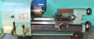
General design and arrangement of a lathe chuck for a metal machine
The following kits are supplied with the cartridge:
- straight cams;
- reverse cams;
- Cam racks are supplied outside the kit.
The most common is the three-jaw chuck, consisting of:
- monolithic or composite body with three radial grooves for cams;
- cams (direct and reverse) are made of high-quality hard, hardened steel of high strength, connected to the end thread of the spiral disk;
- a spiral disk , with a large toothed wheel on its reverse side. Associated with the bevel gear gear;
- bevel gears , by rotating a key inserted into the square hole of this gear, a rotational movement is imparted to the spiral disk.
The simplicity of technological methods for basing parts has become the reason for the popularity and spread of the three-jaw chuck on machines used in production
Key
A metal rod, at one end of which a hole is drilled perpendicular to its axis with a metal lever installed in it. Exceeding the length of the lever by 35–40% relative to the height of the key is optimal.
At the lower end of the rod there is a tetrahedral tip, commensurate with the hole inside the bevel gear. Serves as a manual drive of the cams by rotating the spiral disk while securing the workpiece in the working area of the machine.
Spring
Installed on the tip of the key. Upon completion of the operation, the load from the efforts of the hand on the key is removed and the spring, straightening, removes the key from the cartridge socket. If the machine operator inadvertently does not remove the key himself, then the spring does it for him.
Sleeve
A hollow cylinder, in the upper part of which grooves are cut for half-ring crackers. Provides fixation of the bevel gear in the working body of the cartridge. The upper part of the bevel gear with a groove for half-ring crackers is installed in the inner diameter of the bushing.
Stopper
Screw stops secure the bevel gears in the lathe chuck body.
Gear
The bevel (or small) gear is inserted into the small hole in the chuck body. Its upper part is connected to the grooves of the bushing by means of half-ring crackers.
The small gear is constantly meshed with the teeth of the large gear and is designed to transmit rotational motion to the helical disk of the chuck.
Flange
Adapter flange, faceplate. Designed for a strong and precise connection of the chuck with the working end of the machine spindle. For example, a thread is cut on the TV-4 spindle, an adapter flange (faceplate for a lathe chuck) is installed on it, onto which the lathe chuck is attached.
Spiral disk
Archimedes spiral, snail, planetary. A metal disk with large gear teeth on one side that are permanently meshed with the bevel gear gear.
On the other side of this disk, a spiral profile is cut out, which is in constant contact with the grooves (racks or combs) of the cams. The latter, moving synchronously, work to clamp, center and fix the part in the processing area of the machine.
The part clamped by the cams is removed by rotating the chuck key in reverse.
Reverse cam
Used for clamping large diameter parts. Each cam has two stages for fastening parts for expansion and one prism for compression.
Cam stages are used to eliminate end runout of the part. In addition, machine operators independently create an additional fastening base on the return cams that works to expand.
Straight cam
Straight jaws are used to clamp smaller diameter parts.
Frame
Depending on the design and methods of attachment to the spindle, it can be conditionally divided into monolithic (the body is one basic part) and composite, in which the body is divided into two basic parts:
- Monolithic with a cylindrical belt . It is attached to the spindle through an intermediate flange according to special GOST. Made from high-quality steel and less often from cast iron.
- Composite body . The base part is divided into two components:
- the front part or body (sometimes the front semi-body), it contains a spiral disk and slots for the cams;
- the rear part or flange (often the rear half-body), which houses bevel gears.
Top jaws
They are mounted on the cam rails of the lathe chuck. They are made from unhardened steel grades and are called “raw cams”. Designed for fastening large diameter parts.
AliExpress - Products from China at wholesale prices - Opt-aliexpress.ru
2019 New Men Shoes Fashion Sneakers Canvas Oxfords Breathable High-top Lace-up Casual Platform Plus Size 39-44 | Shoes
Sale
Case for Lenovo YOGA Tab3 10 X50L Smart Cover PU Leather Yoga Tab 3 X50 X50F X50M 10.1inch Tablet+Stylus | Computers and office
Sale
thickness gauge etari et 600 paint coating | Cars and motorcycles
Sale
Vintage motivational posters with historical quotes flags and banners tapestry
Sale
Hot for M42 42mm Screw Rear Lens Camera Mount and Housing Cover |
Sale
220 ML USB Deer Ultrasonic Air Humidifier Aroma With Light Essential Oil Diffuser Car Fogger Cool Mist Maker | Appliances
Sale
Neploe Women's Leopard Print V-Neck Casual Sweater
Sale
Cool Male Anime Hunter X T-Shirt Short Sleeve Cotton Manga Tshirt Leisure Hxh Hisoka Morow Tee Shirt Slim Fit Apparel | Men's clothing
Sale
FYLA MODE 2022 S925 Sterling Silver High Quality Men's Gothic Punk Claw Thingking Skull Skeleton Rings 16MM Width 7.50G PBG030 |
Sale
DIY Smart Assembly Toy Electric Robot Spider Educational Assembly
Sale
SJD-1303IPS 13.3inch Digital Photo Frame 1920 x 1080 HD Screen Desktop Album Display Image MP4 Video MP3 Audio Clock Calendar Fu |
Sale
Indoor Mini Folding Football Soccer Ball Goal Post Net Set+Pump Kids Sport Outdoor Home Game Toy Child Birthday Gift Plastic | Sports and
Sale
New 4PCS 1.5V 2400mWh lithium-ion rechargeable battery | Electronics
Sale
Mumoresip Kids Shoes For Toddlers Big Girls Princess Children Leather Glitter Fabric Mary Jane Wedding Party Dancing Flats | Children's
Sale
New 2022 Women Skullies Beanies Cap Hip For Arrivals Hats Men Beanie Baggy Hedging Winter Knit green Shiny Headgear | Accessories for
Sale
Women's Wedge Sandals White Pearl Sandals with Studs
Sale
Long Sleeve Floral Embroidered Maxi Dress | Themed clothing
Sale
Ciler Men's Cotton Underwear Plus Size Boxers Men's Comfortable
Sale
High Quality 5/6 Gear Shift Adapter for Handle Manual 6 Speed
Sale
Marble Starry Sky Moon Case for Samsung Galaxy S7 Edge S8 S9 Plus S10Plus Note 8 9
Sale
Elsa 2 dress for girls dress evening dresses cosplay clothes
Sale
Rapunzel Princess Dress for Teenage Girls | Children's clothing and
Sale
FIMI X8 SE UAV Aerial Drone Folding Height Stand Landing Bracket (Gear+
Sale
10PCS 29*30mm Two Color Vintage Metal Zinc Alloy Bow love Heart Charms Fit Jewelry Pendant Makings P6639 | Jewelry and accessories
Sale
Main design options
There are several design options for a chuck for a lathe; below we will briefly look at them.
Lever
Until recently, they were popular types of fastenings in lathes. The actions are based on moving the cams using a double-armed lever.
The main characteristic of this type of chuck is determined by the number of locking jaws and the degree of their displacement on the working disk. The position of the workpiece in the working area is difficult to adjust, especially during non-standard processing.
Klinova
Inside the chuck, instead of a spiral disk, a wedge-rack device is installed, through which the cams are shifted and the workpiece is secured.
It is made of especially strong steels that can ensure the invariance of the fixing parameters of the chuck, its uninterrupted and safe operation at high speeds of rotating bodies.
Membrane
Diaphragm cartridge. The pneumatic or hydraulic drive rod presses on the cartridge membrane and bends it. The deflection of the membrane opens the chuck jaws by fractions of a millimeter, and the workpiece is installed all the way into the pins. When the drive is turned off, the membrane returns to its original position and the jaws compress, securing the workpiece.
During processing, the workpiece is held by the elasticity of the membrane, and a large number of cams center the workpiece with an accuracy of hundredths of a millimeter. It is used for finishing machining at low speeds with a small cross-section of the chips being removed.
Wedge cartridges
Wedge chucks demonstrate higher accuracy of workpiece centering than lever chucks. The workpiece is secured using a pneumatic or hydraulic drive, which is located at the rear end of the flat spindle. The three main cams and the cams that are associated with them, during the axial movement of the wedge, move in the radial direction and clamp the product.
For CNC machines where a large batch of parts is processed, it is important to be able to quickly assemble the lathe chuck and change the chuck to a different diameter of the workpiece being fixed, which lasts no more than 2 minutes. For machines with GPS and CNC, chuck designs are being developed with automatic readjustment to a certain diameter of the workpiece. The use of high-quality heat-treated steel for the manufacture of main parts increases the reliability, durability and accuracy of the chuck.
Classifications
Conventionally divided into two groups:
- Cam . Movable segments (cams) fix the part. They differ from each other in design and purpose.
- Collet . Depending on the working position of the collet chuck for a lathe, which secures the part in the desired position, lathe chucks of this type are distinguished:
- with retractable collet;
- fixed collet;
- retractable collet.
Double cam
Self-centering double-jaw chucks. All parts of the product are made of steel; moving parts are subjected to heat treatment, which increases their strength characteristics and wear resistance.
Provide self-centering and fixation of untreated surfaces of workpieces. The dimensions of the working diameter of the chuck are standardized and vary from 125 to 400 mm.
Mounting cartridge used:
- complex shaped parts;
- non-cylindrical and asymmetrical workpieces.
Three-jaw
The locking mechanism of the 3-jaw chuck is made:
- with rack and pinion mechanism;
- with spiral disc.
Rack and pinion
More precisely, a chuck with a spiral disk has a more powerful clamping of the workpiece. Can be used in small-scale or piece production.
Four-jaw
The four-jaw chuck is used when processing asymmetrical workpieces. Allows you to machine a part off-center or when boring holes along different axes.
The product is attached by two pairs of independent holders in mutually perpendicular planes and ensures complete alignment of the spindle axis with the surface being processed.
The cam can be solid or assembled. The chuck with a prefabricated jaw has a base and a mounted jaw. The assembly cam is placed in the groove of the main element and has free radial movement without loss of stability.
This ensures double keyed fastening. The advantage of the design is the rigidity of fixation and ease of use.
Six-jaw
The fixing force is distributed between six cams, which allows you to fasten a thin-walled part without fear of its destruction or deformation.
Collet chucks
The main working element of the collet chuck is a sleeve with several axial slots that divide it into petals, which, depending on the diameter of the workpiece, can be three, four or six. Such petals play the role of cams that compress the part that is inserted inside the sleeve. Collets are available as feeding and clamping. The feed collet is a hardened steel sleeve with three partial cuts that form petals with their ends pressed together. Solid clamping collets are made in the form of a bushing with spring-type petals.
Adhesion increases due to the narrowing of the slots during the procedure of pressing the collet into the cartridge with the conical part. From a technical point of view, the design of a lathe chuck with a collet has some advantages over other clamping devices - for a part that is fixed in a collet, the radial runout of the product is so insignificant that they can easily be ignored.
The primary area of use for such chucks is clamping cylinders, short bars or bushings for processing. They are also used for fixing cutters, drills, wrench tips and taps. Collet chucks are popular for secondary clamping of surface-machined workpieces. If the profile of the workpiece does not match the shape of the collet hole, it is customary to use replaceable inserts.
Manufacturing materials
The lathe chuck body is made of cast iron or hardened steel. The chuck with a steel body allows you to operate at increased speeds.
Cast iron
Due to the low resistance to sudden mechanical loads, the quality indicators should be no lower than those of the SCh 30 brand.
Steel
The specific use of steel grades is not provided for by GOST; the manufacturer himself chooses the steel grade. However, the most common steels must have a strength limit σB of at least 500 MPa and heat treatment of the working surfaces to a hardness of at least 43 HRC (s).
Lever chucks
Lever chucks can be used in small-scale production because their changeover procedure is simple and can accommodate workpieces in a wide range of diameters. On the centering surface in the cartridge body there is a disk, on the side of which there is a thread along an Archimedean spiral, a conical gear rim is cut on the other side.
The workpiece is secured in a lever lathe chuck by a hydraulic drive, which moves the rod with the coupling. The rods with crackers, which form a double-armed lever, are capable of rotating around the center of the cylindrical section of the cracker, moving the sliders with cams to the center and clamping the workpiece. Changing the lever chuck is simple and comes down to simultaneously moving all the jaws to the required radial position using a key.
This operation takes no more time than the procedure for securing the workpiece in a three-jaw chuck, which has a non-mechanized drive. Due to the moving elements that are provided in the drawings of lathe chucks and connect the slides to the main cams, errors in the centering of the workpiece are significant, so lever chucks are used mainly in roughing operations.
Basic dimensions and designations
Dimensions of three-jaw chucks. Standardized according to GOST 2675-47:
- nominal diameter: from 80 (mm) to 630 (mm);
- internal diameter: from 16 (mm) to 190 (mm);
- width: from 50 (mm) to 125 (mm);
- jaw width: from 12 (mm) to 60 (mm).
Dimensions of four-jaw chucks:
- cartridge diameter: from 80 (mm) to 1000 (mm);
- outer diameter of the connecting cone: from 82.563 (mm) to 285.775 (mm);
- machine spindle size: from 5 (mm) to 15 (mm);
- bore diameter: from 40 (mm) to 200 (mm).
The designations of foreign-made cartridges are read in accordance with their accepted standards and are available in print for decoding. For example:
Table of lathe chucks produced by JSC BelTAPAZ
Lathe chuck 3–200.33.14 P
- [3] - number of cams;
- [200] - outer diameter of the cartridge, mm;
- [33] - characteristic determined by the type, design, outer diameter of the cartridge;
- [14] - Modification;
- [P] - accuracy class.
How to choose
To choose the right lathe chuck, you need to consider several important points:
- operating parameters and exact dimensions of the machine spindle;
- method or option for attaching the chuck to the spindle;
- for hobby machines, drive power plays an important role; a weak engine may not cope with the torque task;
- what and how many parts are included in the lathe chuck kit.
Without a clear understanding of the information presented above, you cannot consider yourself ready to purchase a lathe chuck as an important component of the machine.
You need to understand that the quality and productivity of a lathe affect the quality and productivity of labor and material condition.
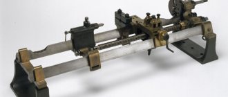
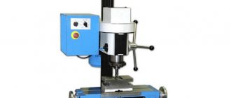
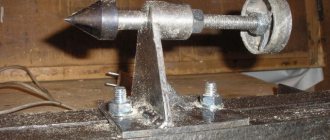
How to assemble according to drawings yourself
For a beginner to work on metal, it is possible to assemble a home-made chuck, but the whole process will become a headache due to searches, inconsistencies, errors, etc. Making a lathe chuck for woodworking is much more affordable, although not easier as it might seem.
First of all, for the work to proceed, it is necessary to create a detailed assembly drawing with detailing drawings. After the drawings, events will follow. Without drawings and an action plan, it is unlikely that anything worthwhile will be achieved, because anyone who acts without a plan acts for a long time and poorly.
Then the process of collecting components and materials begins. The process of implementing ideas is the most reverent and carries with it a powerful stream of self-renewal. And successful completion becomes another favorable stage in creative life.