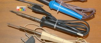
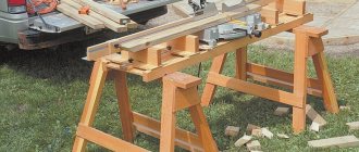
The main working tool of a radio amateur or equipment installer is an electric soldering iron, which cannot be used without a stand that is suitable in size and reliable in operation.
In amateur radio practice, a homemade stand for a soldering iron is most often used, the design of which is selected depending on the specific conditions of use.
As a rule, it consists of a base and two support posts on which the tip and handle-holder of the heated soldering device are placed.
Stand accessories and tools
If you have plans to make a soldering iron holder with your own hands, then you need to find the necessary tools and things that will help you realize your plans. The main items you may need for this include:
- A metal sheet;
- Wooden board;
- Screwdriver;
- Wire;
- Metal can;
- Screwdriver;
- Electric drill;
- Screws with nuts or self-tapping screws.
Depending on what kind of do-it-yourself soldering iron stand you will make, you may need a different set of tools and parts. But most people choose these options because they are the most convenient.
Wire soldering iron stand
Making a wire stand for a soldering iron with your own hands begins by straightening the wire itself.
To get started you need:
- Cut a piece of wire 0.3 meters long;
- Clamp one end of the wire with pliers, and then wrap the remaining length around the tool several times;
- With the other end you need to do the same procedures;
- Stretch the wire from this position in different directions with two pliers
- Next you need to start making the stand. The straight wire must be divided into several parts. It is worth making a rectangle out of it, for example, with sides of 5 and 10 cm. It is advisable to solder this structure so that it retains its shape. At the same time, you need to solder the top part. To do this you will need a few more pieces of wire. Thus, on one of the sides of the resulting rectangle there will be another “U”-shaped structure soldered to its ends. The upper part of the structure can be bent to the bottom so that the soldering iron does not roll off it.
- On the other side of the base rectangle, a similar “U”-shaped structure of the same or a different size should be made. With the same values, a homemade soldering iron stand will hold the soldering iron in a vertical position. Otherwise it will be tilted. The upper parts of the towering forms must be soldered together for stability. Then you need to check the structure for strength by installing a tool on it. If everything is fine, then the do-it-yourself soldering iron stand made of wire is ready.
Homemade soldering iron stand with your own hands
Many offline and online stores sell good and quite convenient stands for soldering irons, and inexpensively. But if you wish, you can make them yourself. It will be cheaper, plus you can adapt the stand to your own needs.
There are a lot of ideas for making them, so we decided not to limit ourselves to just one, but to make a selection of the most interesting, in our opinion, homemade soldering iron stands, made with our own hands.
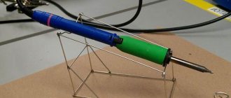
Soldering iron stand made of wire.
Let's start with the most budget-friendly, simple and common option. In it, the mount for the soldering iron is made of thick metal wire in the form of a conical spring and is attached to a wooden or other base. Instead of wire, you can use thin metal clothes hangers, which are found in almost every home.
Such a stand can be made more convenient if you install additional goodies on it, for example, a metal sponge for cleaning a soldering iron, a box for tin and rosin, or a holder for soldering.
You can make another homemade stand for a soldering iron from wire, which is a little less convenient (although this is a matter of taste) and just as easy to make.
Soldering iron stand made from fuses.
Another option is a stand that is very easy to make and does not require any money. The base is made of a wooden block or textolite; fuse jaws of the required size are attached to it on top.
Mobile stand.
A homemade mobile stand for a soldering iron, made from sheet metal obtained from a burnt computer power supply. The stand is intended primarily for people who often solder outside the home. It is quite comfortable and functional, and easily fits into a bag or even a jacket pocket.
Having such a stand, you do not have to carry tin, rosin and a clamp separately for soldering small parts. Where and what to store is clearly shown in the video, we recommend watching it.
Well, you can find the manufacturing instructions here.
DIY soldering iron stands.
Complex multifunctional stands are a matter of taste. Some people really like them, while others prefer the simple designs we showed above. In any case, the complex stands deserve attention, as they are well made. We will show only a few of them, the most interesting in our opinion.
The first stand has everything you need for comfortable work, namely a place for tin and rosin, a clamp for soldering small parts, a sponge for cleaning the tip, a built-in regulator, and the actual fasteners for quick but reliable fixation of the soldering iron.
See the manufacturing process here.
Well, and two more and no less interesting ideas in video format.
The simplest stand.
If you urgently need a stand for a soldering iron, then making something complicated is not the best idea, since haste always leads to a mess. It is better to temporarily make a simple design, and then change it to something more worthy.
The best option, which can be done in just a couple of minutes, is a wooden block with four long screws. The soldering iron fits well on it, is easy to pull out, but does not fall out on its own.
Soldering iron stand made from fuses
A do-it-yourself soldering iron stand using improvised materials is the simplest and cheapest way to get the desired design. To create a stand from fuses you need:
- Textolite, or as its replacement - a wooden block;
- Circuit breakers.
The block is prepared as a base, so its surface must be flat for greater stability. After preparing the base, the fuse jaws are installed on the product. The distance between them is selected individually according to the size of the soldering iron. They can be secured using self-tapping screws, since there is always a hole on the sponge where they can be located.
Fuse stand
The product is easy to manufacture and does not require special materials. For holders, fuse jaws are used, which are attached to a base made of a wooden block or PCB . The distance between the holders is set in accordance with the size of the soldering tool. The fuses are screwed using self-tapping screws into pre-drilled holes.
If you urgently need a soldering iron, you can quickly make a stand from screws or nails. Nails are driven crosswise into the wooden base. This design is quite stable and holds the tool well.
To make a homemade soldering iron stand, you do not need any special knowledge or skills. For work, scrap materials that can be found in any home are often used. DIY devices are simple and easy to use.
Originally posted 2018-07-04 08:11:06.
How to make a complex stand?
A do-it-yourself soldering iron stand made of wood and other extremely simple varieties often turn out to be of little functionality. For those who are constantly engaged in soldering, more complex options may be required, in which additional devices will be placed, and the holder itself will also look more serious.
First comes the manufacture of the base of the stand, which is best made from a wooden block or board.
- A width of up to 10 cm is quite sufficient; sometimes you can get by with smaller sizes. The length can be 15-20 cm, but this will depend on the size of the soldering iron used. "Important! The main criterion here is the stability of the surface, therefore, the wider it is, the more stable the position of the soldering iron will become.”
- To create supporting elements, two metal strips are cut out. They need to be bent so that they create a frame, the upper part of which will contain a deflection for placing a soldering iron on them. The dimensions of such arms and their location are selected according to the size of the soldering iron. To attach the arms, you need to make holes in them and then secure them with self-tapping screws.
- This is the main part, but to complement it, you can place a jar of rosin in the free space. To do this, it is enough to drill a hole in the prepared container and fix the jar through it to the stand with a self-tapping screw.
- One of the most difficult options may seem to be a do-it-yourself soldering iron stand with a power regulator. This is relevant in cases where a complex product will also serve as a power source, along with an extension cord. Then it is reasonable to first allocate a place for mounting the power regulator. They can be found in specialized stores with various required parameters. A socket is connected to the wooden base, from which a plug is connected to a wire of the required length to connect to the network. The socket housing can also be purchased from relevant stores. After this, the prepared regulator is attached to the board.
Soldering stand with LED lamp, holder and other bells and whistles for a beginner
Hello everyone, today is an express review of something that every owner of a soldering iron needs (unless, of course, there is a better substitute). Under the cut you will also find something that I forgot in the two previous reviews. The solution is under the cut. Picture for starters:
Warning, lots of photos. So, before us is a 100500v1 tool for a beginning solder. Let's take a look at the characteristics:
Lens diameter: 90mm & 34mm (2 pcs) Power: External or 3 AA batteries (not included) Power supply: Input voltage 110-240V 50/60Hz, Output: 4.8V DC, 250mA Plug: European Holder dimensions: length 6.3 cm, diameter 2.7cm & 1.8cm Base dimensions: 10 * 6.8cm Let's start with the appearance. The box arrived slightly wrinkled, but overall fine. Inside there was an abundance of bubbles and the holder itself was in pieces.
Complete power supply, small, light, not
powerful
(stated 250mA, 1A is written on the case, but I don’t believe it, more like 250).
It seems that the package also includes an alternative power source in the form of a lanyard USB-round power connector, but I can’t say for sure, maybe I took it somewhere else, not in the photo. Well, another alternative is powered by AA elements, popularly called finger batteries. For me - unnecessary functionality, where I will solder there will always be 220 volts or 5 from usb.
Despite the fact that in the photo you can see the inscriptions AAA, it is AA that is inserted there.
Next, lenses, 3 of them, one large and two small. The large one slightly magnifies everything, the small ones - very much, I really liked looking at the markings on the chips with them, it’s a completely different matter. The small lenses are interchangeable and can be detached from the larger lens and used as a “magnifying glass.” The mount for small lenses can be moved closer/further relative to the main lens.
LED lamp with 5 LEDs, on a flexible leg, with a switch. It shines well, stronger light is no longer needed - it will overexpose.
Now the whole thing is assembled and in operation: The stand holds the soldering iron and doesn’t fall over, but the soldering station has its own stand, so I’ll most likely twist this spiral if I don’t come up with a use for it.
I’ll steal one photo from the seller (the seller stole it from someone else anyway):
Pros:
+ The crocodiles hold + Good magnifying glasses + Large lens on a hinge + Good backlight + PSU included + Normal quality, from the “China factory” series + Adjustable in all directions + Good weight distribution, you can add weights to the battery connector for reliability Cons: — Stand for a soldering iron of dubious usefulness — Crocodiles won’t handle a large fee
Conclusion: If you're too lazy to go to your local pip-and-bib
and buy this stand at exorbitant prices, you can order it from the Chinese. Before this stand appeared, I swore a lot when I tried to solder and even burned the table. I hope this is in the past now
And, finally, the promised forgotten, I forgot the cat in previous reviews, I categorically apologize
Cat
Ready to answer questions.
update
: the store where I bought it was out of stock.
Model name MG16129-C. update2
: guys, please understand and forgive.
Such a low price relative to Ali was because I took the lot with paid delivery
, at that moment it was the cheapest offer. Accordingly, the fact that now on Ali for 15-16 bucks with free shipping is the cheapest offer. So it goes.
My other reviews
Mega-review-hacking of 5 Chinese cheap portable routers, we continue to play hacker, at a new level Hame a15 clone, which surprised me, or when a copy is better than the original. Let's play hacker or zyxel keenetic 4g for 10 dollars Remote control of the Chinese company CHUNGOP with untapped potential Yagi antenna 2100 MHz or a comparative review of four 3g/4g antennas in a summer cottage Vonets-MINI300 access point Soldering stand with LED lamp, holder and other bells and whistles for beginner Flashlight... in the USB port. With an element of surprise Antenna 4g+3g Cute cables, durable, striped, braided, 10 pieces, part 2 Cheapest HD IP camera Box for a 2.5″ hard drive (+ spy stuff) Cute cables, durable, striped, braided Screen with two tulip inputs Portable dream router NEXX WT1520 (conversion in openwrt)
Manufacturing options
There are several options for stands - depending on the specific requirements for soldering functionality, choose any one.
Regular
- First, prepare a wooden board - the base of the stand.
- Select a piece of board - for example, 25*12 cm.
- Mark the points on the board according to the drawing and drill holes in these places. The diameter of the holes should be slightly smaller than the cross-sectional diameter of the wire - it should fit into them with great effort.
- Cut the required piece from a coil of steel wire and mark it with a marker. Bend it along these points, as shown in the drawing. You will get an M-shaped frame - its dimensions can be, for example, as follows: two sidewalls of 5 cm each and two sides (slopes) of 3 cm each. There should be two such frames.
- Press the ends of the frames into these holes.
The simplest homemade soldering iron stand is ready. If desired, it can be modified as follows.
If rosin and solder are sold in ready-made industrial cylindrical capsules, then drill a hole using a core drill of a slightly smaller diameter than the capsule itself. It may not be through.
Press the capsule itself into this hole. Before inserting it, this container can be coated with glue - for example, universal “Moment-1”, then it will not fall out over time. There can be 3 of these capsules: for rosin, solder and flux. It is advisable to choose a glass container for soldering flux.
To prevent the hand-made stand from scratching the varnished surface of the table, legs are attached to it.
Do the following.
- Cut four identical circles with a diameter of no more than 1 centimeter from a piece of thick (from 3 mm) rubber. Here, rubber from old car inner tubes can be used as a consumable material.
- Using an emery block, a sharpening stone, or a grinding machine, sand the rubber on one side and the base underneath where these circles are installed.
- Apply a layer of the same Moment-1 glue to the stand and to the circles themselves. After a few minutes, use a vice or clamp to firmly press them to the piece of wood where they are glued. Compression is also carried out by pressing with your hand on the stand installed on these mugs, and any horizontal surface that can withstand the force applied to the stand serves as a support.
- After a day, the glue will completely dry and harden, and the stand can be used.
- Stands of increased sizes are used for powerful soldering irons of 100 watts or more, as well as for blowtorches running on gas.
Casket
The box design is the most compact and easy to carry. It is made from any wooden or metal box shaped like a parallelepiped. The soldering folding box is a pencil case with several compartments in which capsules with flux and rosin and a roll of solder are stored.
Fixation of such a pencil case in the closed state is carried out using M-shaped wire inserts. If the pencil case is large enough in size - for example, 25 * 12 * 5 cm, then the soldering iron itself will fit into it. The volume of such a box is enough to, in addition to soldering consumables, accommodate the soldering iron itself, its power cord and plug when folded.
- If you don’t find such a stand on sale, you can make it yourself from wood. Natural wood or plywood with a thickness of no more than 1 cm is suitable as a consumable material.
- Mark and cut a sheet of wood for the parts of the future soldering case.
- Connect them using furniture corner screws made from wood glue. You will get a soldering box with sections.
- Cut another piece of wood or plywood the size of the bottom wall of the pencil case. Attach it to 2 small furniture hinges. You will get a lockable box.
- At the ends of the pencil case, closer to the bottom, drill holes for wire inserts that serve as supports for the soldering iron when the pencil case is open.
- Make these inserts according to the above diagram and install them in the place intended for them.
- Installation of the inserts is carried out the next day - when the glue dries and hardens. The pencil stand is ready for use.
With diode
The purpose of the diode is to reduce the supply voltage by one and a half to two times. This significantly saves the life of the soldering iron.
The fact is that periodically there are significant interruptions in work when the soldering iron is not actively used. In order not to keep it constantly turned on at full power, and also to eliminate the loss of time for its complete, “from scratch”, warming up when it is needed again, a diode - or a step-down regulator - is simply necessary.
Long-term operation of the soldering iron at a temperature significantly lower than 300-odd degrees prevents the nichrome wire from which the active (heating) element is wound from burning out prematurely. Periodic overheating of the soldering iron can also cause the layer of mica to crumble, transmitting heat from the heated spiral of the steel structure to which the copper tip is rigidly connected.
To build a heat control circuit into the stand, do the following:
- Install on the stand a small-sized switch, pre-built into a small rectangular housing. In parallel, a high-voltage diode should be connected to it, designed for industrial mains voltage up to 300-400 volts. This refers to the reverse voltage that a given diode can withstand. The current strength (we are talking about direct current) must be at least 200 milliamps. All these characteristics are indicated in the description of the specific diode.
- Connect an additional power cord to the stand - it is the one that is connected to the 220 volt lighting network. Connect a switch with a diode into its gap.
- Mount a compact, small-sized socket at the output of the stand. Connect it to a switch with a diode.
Reliably insulate all live contacts. The stand with diode is ready for use.
Scheme
The controller circuit, as I said, is not mine. I found it on the Soldering Iron website, a diagram from Mikha-pskov, proposed by a participant in the Soldering Iron forum under the login KLARUS
.
ATmega8
microcontroller ; it uses a three-digit LED indicator as a temperature indicator. I installed the green one with a common anode.
Hair dryer controller circuit.
The circuit allows you to maintain the set temperature of the hair dryer, regulate the speed of the hair dryer fan motor, when the hair dryer is turned off, it waits until the temperature of the hair dryer drops to 50 degrees, then removes power from the hair dryer. The circuit also turns off the hair dryer in the same sequence if it is installed in a hair dryer holder (on a stand) that has a built-in magnet, since the hair dryer has a built-in reed switch for this purpose.
Hair dryer holder
I would like to draw your attention to the diagram, in particular to the speed controller of the hair dryer motor. As you can see, the circuit uses a 12-volt motor in the hair dryer fan; in our case, a 24-volt motor is used. The changes that will need to be made in the circuit are as follows: in the lower part of the potentiometer R34 according to the circuit, we connect a 4.7k or 5.1k resistor in series (select the minimum motor speed so as not to blow off parts from the future board with smd you are assembling)). After such modification, the voltage at the output of the regulator will increase to the 24V we require. Yes, and also, if you use a hair dryer with a 12-volt fan, then there is no need to make the output voltage of the power supply 30 volts; in this case, 14 volts will be enough.
I assembled a switching power supply for this controller. The output voltages of the power supply in my version are +30 and +9 volts. The circuit is assembled on a UC3842 PWM controller.
Hairdryer controller power supply circuit.
Basically, all the necessary functions are available, and most importantly, it all works quite reliably. The circuit itself is powered by a stabilized voltage of 5 volts. The stabilizer is made according to the standard scheme on the LM7805; it is not shown on the diagram, but is on the seal on the main board.
PCB holder
The simplest version of the holder is a pair of electrical installation “crocodiles”. They are positioned so that they are turned in one direction. They are installed on supports made of linear sections of the same wire from which the inserts holding the soldering iron are made. There is also a more advanced device with brackets and guides that allows you to hold printed circuit boards prepared for soldering more firmly and reliably. The PCB retainer can be installed anywhere on the stand.
Printed circuit boards
After I found the case, I began to convert the printed circuit boards that were on the Soldering Iron website to fit this case. In particular, on the controller board (Main) I removed the rectifier from diodes and the diode assembly, since they were not necessary in my case, and I adjusted the size of the board to my case.
Main board. View from the parts.
Main board. back side
The indicator and control board (buttons and regulator) was also completely redesigned to fit my case.
Indicator board.
Indicator board, reverse side.
All stabilizers (317 and 7805) on the main board are installed on small radiators. A VT139 triac is also installed on the radiator, which controls the hair dryer heater. The radiator on it is slightly larger and it itself is located on a separate board.
Hot air gun heater control board
The power supply, as I already said, in my version is switching. Well, it was easier for me. It is assembled on a separate printed circuit board:
PSU board. View from the parts.
PSU board. Back side.
General requirements for materials and design
You can make a high-quality stand with your own hands, used for soldering various products and metal parts, from any available means that meet the following requirements:
- reliability and stability of the foundation;
- fire resistance of the material of the support posts;
- availability of space for containers with rosin and solder.
The simplicity of the device in question does not mean at all that you can use low-quality parts to assemble it and treat it as something not particularly important.
On the contrary, to make a stand for a soldering iron you will need durable and reliable materials suitable for working at high temperatures, as well as accurate calculation of the dimensions of the base with holders and containers placed on it.
- Jars of rosin and solder attached to the base must be placed in an order corresponding to the sequence of operations performed during soldering and not interfere with the work with the soldering iron.
- Some craftsmen place soldering irons along with a power regulator on such stands, which significantly complicates the design of the entire device as a whole.
- Unlike small-sized factory samples, self-made stands must have dimensions sufficient to accommodate all the elements listed above.
- Sometimes such devices are equipped with a special holder for a soldering iron (the so-called “third” hand), which allows you to fix the workpieces or parts being processed. One of the simplest product options is a crocodile-type holder.
Simple version
To assemble a simple, convenient stand with a minimum of parts yourself, you may need the following consumables:
- a wooden flat piece made of beech or oak measuring approximately 25 by 12 cm, necessary for making the base of the soldering iron stand;
- duralumin plates no more than 1.5 mm thick;
- miniature metal containers (brass cups from an old-style telephone call can be used to make them).
After all this material has been prepared, you can proceed to assembling the stand for the soldering iron itself, starting with preparing the seats for containers with rosin and solder.
In the case of using brass cups from a ringing device (bell), they are simply screwed to a wooden platform in a pre-designated location.
After this, triangular or oval shaped supporting elements are made from a duralumin plate (the distance between them is selected according to the length of the soldering iron).
The supports formed in this way are attached to the base of the stand using self-tapping screws or large screws.
If necessary, the height of the supports for placing a soldering iron can be increased by lengthening them using short metal stands with threads at the ends.
All prepared parts should be carefully processed with a file, and then their surfaces should be cleaned with sandpaper, which will smooth out sharp edges and remove dangerous burrs.
Soldering iron stand - what is it for?
A high-quality part is necessary for those people who do a lot of work with soldering. To make such a device as a soldering iron stand, no special skills or abilities are required. The process uses simple and accessible materials and tools. The finished device is easy to use. A homemade soldering iron stand should consist of separate elements. First of all, special containers are provided for rosin, flux and a department for mixing them. Some models are equipped with a box where small parts are stored. The soldering iron stand is suitable for any device, regardless of its power and degree of heating.
When making the structure, the location of these containers should be taken into account. Everything should be located so that it is convenient for the master to solder.
Stand with “third hand” device
This design allows you to work with the soldering iron as comfortably as possible, without wasting effort on holding the soldering iron and the two parts being connected at the same time. It is quite deservedly called the “third hand”.
To make it you will need the following available materials and accessories:
- two glasses from decorative candles;
- a leg from an old table lamp or small lamp;
- two alligator clips;
- a magnifying glass that will make it much more convenient to work with small details;
- a spring retainer, which you can make yourself from ordinary steel wire;
- wooden base.
The first step is to prepare the basis for the future stand. To do this, we mill three niches in it. The first two will be used to install candle cups, and the third will be used for a cleaning cloth that removes solder from the soldering iron.
After this, all work is performed in the following sequence:
- We mount the cups in the prepared niches.
- We mount alligator clips onto the flexible lamp rod. It is better to make the distance between them adjustable.
- We install the spiral soldering iron holder in one of the corners of the base.
- We drill holes and screw the rod with clamps to the wooden stand.
- If desired, you can attach a magnifying glass to the top of the “third hand”. Also very often it is made removable or installed on a separate rod.
- This stand does not require significant financial investments, but makes working with a soldering iron easier.
From scrap material
By using materials that are available in the house, you can save the costs required to make the stand.
To build a convenient structure you will need to prepare:
- coarse sandpaper;
- hacksaw for metal;
- Phillips screwdriver (you can use a screwdriver);
- thin screwdriver;
- iron plate;
- a spring that can be removed from the pen;
- a tin covering the board (can be removed from a broken receiver);
- metal retainer from the antenna;
- self-tapping screws 20 mm - 4 pcs.;
- bolts - 4 pcs.;
- Thin-sheet chipboard (up to 18 mm).
Also during the work, in addition to improvised means, you will need pliers and 2 rubber stoppers from chemical test tubes.
For reference! On Avito or Yula you can find craftsmen who make interesting and unusual stands for soldering irons. Such products look almost like works of art.
Step by step guide:
- The cut chipboard sheet is sanded, giving it a rounded shape.
- Rubber plugs are sawn straight. To achieve uniform thickness, you should use sandpaper.
- 1 self-tapping screw is screwed into each rubber leg.
- Holes are made in the structure and legs with screws are screwed in.
- The iron plate is bent, giving the outline of a hook.
- Using a screwdriver, holes are made for a pair of bolts intended to secure the hook.
- The final stage of making a stand from scrap material will be tightening the bolts and checking how well the hook holds.
How to make it yourself
How to make a soldering iron stand with your own hands? To make it, you first need to make a stable base from a material that conducts heat poorly. The following tools and materials are required for work:
- chipboard sheet (18 mm);
- coarse sandpaper;
- self-tapping screws (20 mm), small bolts;
- screwdriver, pliers;
- screwdriver;
- a piece of rubber;
- iron plate.
A rectangular blank is cut out of a sheet of chipboard, and the sides are sanded with sandpaper, rounding the corners. Next, make four rubber legs, which can be cut from a piece of rubber or a cork from chemical test tubes. The legs are screwed to the base using self-tapping screws.
A hook is bent from a long strip of iron with pliers, which is used to install the heating part of the soldering iron. At one edge of the stand, an iron strip with a hook is secured with bolts. To reliably fix the structural elements, you need to pre-drill holes in the chipboard workpiece.
The holder for the soldering iron handle can be made from any part with a suitable recess . It is bolted to the edge of the music stand . Closer to the heating element, a soldering holder is installed in the same way. To do this, use a metal plate made from old radio components or other consumables.
At the soldering site, you can melt a piece of tin, which is heated during operation. This results in a convenient and versatile device. Rubber feet give the structure stability and prevent damage to the table surface.
Soldering iron stand with power regulator
This type of design is equipped with a device that independently adjusts the heating level of the hand tool. This prevents overheating of the device and extends its service life.
In the process of making the stand, the home craftsman will use:
- copper wires;
- a piece of plywood;
- elements for fixation;
- tin boxes;
- rubber feet;
- socket.
You will also need a transformer, diodes and a resistor.
Step by step process:
- During the assembly work, the master assembles a power level control board according to the diagram.
- Using a heat gun, you need to make a plastic blank for the board body and solder the corners of the tin box.
- At the next stage, a tin box is made for the brush, with the help of which the tip is cleaned and the stop for the device is assembled.
- Next, the bolts on the clamp are soldered (like a third hand) and the base of the structure is made of plywood, on which a recess is cut for further placement of rosin melted with a hairdryer.
- Metal boxes, clamps and stands are fixed, after which the board is screwed in and the housing part is secured.
- The final stage of making the stand is to screw the brush box and fix the anti-slip rubber feet on the back side.
The abundance of options for making stands at home allows each craftsman to choose the most suitable method for himself. By strictly following the step-by-step guide, you can quickly build a convenient design that will prevent damage to surfaces when using a soldering iron.
Recommendations
For stands with a diode, select the diode itself in terms of power, with a margin designed for a specific soldering iron. For example, 25 W soldering irons will require a diode with a maximum operating current of 110-120 mA, and taking into account a 2-3-fold reserve to prevent overheating of the part itself, the maximum operating current will reach 0.3 amperes. The use of diodes with a reverse voltage less than 300 V is not allowed - if the voltage is at the limit or slightly beyond the limit, thermal and electrical breakdown will occur.
Do not use plastic as the main material - the heated inserts of the holders, which transfer excess heat in a matter of seconds, will quickly melt it. The holders will fall to the side, and the soldering iron will “move” off the stand onto the table.
It is recommended to use heat-resistant and non-flammable power cables. Ground the soldering iron body separately.
Construction and details
Any LED built-in indicators, both with a common anode and a common cathode, can be used as indicators. You can also use individual indicators by connecting their segments in parallel. Firmware for these two options is included in the trailer. Both should work, but I have not tested with a common cathode.
The power supply transformer is made on a PQ2625PC40 core purchased on Aliexpress. Since the output stage of the power supply unit is single-ended, the transformer core must have a gap of 0.35-0.4 mm. The primary winding contains 34 turns, wound with wire with a diameter of 0.45 mm. The PWM power winding contains 5 turns, wires with a diameter of 0.25 mm. The secondary windings are wound in two wires with a diameter of 0.5 mm and contain: 30-volt winding - 9 turns; 9 volt winding 3 turns.
Transformer core
It is quite possible to use any cores from computer power supplies, but they must be rewound according to calculations in the Flyback 8.11 calculation program, and if the core has no gap, then, according to the calculations, assemble the core with the required gap. The figure below shows the calculation for an example for a core from a computer power supply.
Calculation of a transformer on a core from a computer power supply.
In general, you don’t have to bother with a switching power supply and assemble it on a regular power transformer, which has two secondary windings at the output with output voltages of 7-12 and 24-28 volts. In terms of dimensions, it will be no larger than a switching power supply, since the currents consumed by the controller and the hair dryer fan are not large, and it will be enough for the maximum current of the secondary windings to be 0.3-0.5 Amperes.
All printed circuit boards are made using the well-known LUT technology. Inscriptions and drawings on the boards from the parts side were also applied using this technology.