The main load of pipelines falls on the supporting structures. The elements hold the pipes in the designed position and prevent them from sagging. Calculation of the optimal distance between supports is a necessary stage in the design of heating networks.
SNiP 2.09.03-85 regulates the design of industrial structures, including supports for steel pipelines. Building codes and regulations determine the minimum step - 6 m, a multiple of 3 m. In cases where the route approaches various buildings, crosses roads, railways and other communications, it is allowed to use other sizes.
The distance from the support to the weld should allow for local heat treatment and control of the joint using non-destructive methods. For pipes with diameters up to 50 mm, a distance of at least 0.5 cm is prescribed, with a diameter over 50 mm - at least 2 cm. The calculation of the span between supporting structures is influenced by the principle of their operation.
The distance between the supports when installing them: what should it be?
The question often arises at what distance from each other the supports should be located when installing them. Here we provide a summary table of the values of these distances between spans for sliding supports of steel pipelines for above-ground and underground installation.
Distance between supports
| Pipe outer diameter, mm | Pipe wall thickness, mm | Maximum permissible distance, m | Accepted distance for above-ground and underground installation in tunnels, m | Accepted distance for underground installation in non-passable channels, m |
| 25 | 2,5 | 2,5 | 1,9 | 1,9 |
| 32 | 2,5 | 3,2 | 2,7 | 2,7 |
| 40 | 2,5 | 3,9 | 3,0 | 3,0 |
| 57 | 2,5 | 4,9 | 3,8 | 3,8 |
| 76 | 3,0 | 6,4 | 4,9 | 3,8 |
| 89 | 3,0 | 6,9 | 5,3 | 4,1 |
| 108 | 3,5 | 8,3 | 6,4 | 4,9 |
| 133 | 4,0 | 9,6 | 7,4 | 5,6 |
| 159 | 4,0 | 10,4 | 8,0 | 6,1 |
| 219 | 4,0 | 12,8 | 9,8 | 6,4 |
| 273 | 4,5 | 14,7 | 11,3 | 7,9 |
| 325 | 5,0 | 16,6 | 12,8 | 8,3 |
| 377 | 5,5 | 18,3 | 14,1 | 9,2 |
| 426 | 6,0 | 19,8 | 15,2 | 9,9 |
| 530 | 7,0 | 22,7 | 17,5 | 11,4 |
| 630 | 8,0 | 25,6 | 19,7 | 12,8 |
| 720 | 8,5 | 27,7 | 21,3 | 13,9 |
| 820 | 9,5 | 30,3 | 23,3 | 15,2 |
| 920 | 10,0 | 31,9 | 24,5 | 16,0 |
| 1020 | 11,0 | 33,6 | 25,8 | 16,8 |
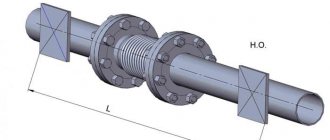
When installing movable supports, it is necessary to take into account their mounting displacement relative to the support strips on the cushions, depending on the direction of temperature deformation.
Schemes of compensated areas
* For supports of the same size in sections A-B and B-C
oporamet.ru
Distance between pipeline supports
When laying pipeline systems for various purposes, several types of supports are used. Depending on the load placed on the highway, as well as the location of the metal structures, the appropriate type of supports is selected. Another important parameter is the distance between pipeline supports, which depends not only on the contents of the pipes, but also on their diameter. Properly selected and installed structures ensure the reliability and durability of the systems.
Varieties
The construction of pipelines involves the calculation of all parameters that affect the condition of the pipelines. Depending on the identified features, fasteners and support modules are selected.
There are two main types of supports:
- Movable
- Fixed
Each type provides strength and reliability of fastening, and also helps to level out vibration. All movable structures can only be installed in open areas or in tunnels. NOPs provide the most reliable fastening, which is very important when laying pipelines and process lines. NOP are mounted:
- On turns
- On the climbs
- Near the shut-off valves
- Evenly along the entire length
The distance is determined individually in accordance with the size of the pipes and the method of their installation.
Distance between pipeline supports SNIP table
At the state level, there are standards that regulate the distance between supporting structures.
| Pipe outer diameter (mm) | Pipe wall thickness (mm) | Maximum permissible distance (m) | Accepted distance for above-ground and underground installation in tunnels (m) | Pipe wall thickness (mm) |
| 25 | 2,5 | 2,5 | 1,9 | 1,9 |
| 32 | 2,5 | 3,2 | 2,7 | 2,7 |
| 40 | 2,5 | 3,9 | 3 | 3 |
| 57 | 2,5 | 4,9 | 3,8 | 3,8 |
| 76 | 3 | 6,4 | 4,9 | 3,8 |
| 89 | 3 | 6,9 | 5,3 | 4,1 |
| 108 | 3,5 | 8,3 | 6,4 | 4,9 |
| 133 | 4 | 9,6 | 7,4 | 5,6 |
| 159 | 4 | 10,4 | 8 | 6,1 |
| 219 | 4 | 12,8 | 9,8 | 6,4 |
| 273 | 4,5 | 14,7 | 11,3 | 7,9 |
| 325 | 5 | 16,6 | 12,8 | 8,3 |
| 377 | 5,5 | 18,3 | 14,1 | 9,2 |
| 426 | 6 | 19,8 | 15,2 | 9,9 |
| 530 | 7 | 22,7 | 17,5 | 11,4 |
| 630 | 8 | 25,6 | 19,7 | 12,8 |
| 720 | 8,5 | 27,7 | 21,3 | 13,9 |
| 820 | 9,5 | 30,3 | 23,3 | 15,2 |
| 920 | 10 | 31,9 | 24,5 | 16 |
| 1020 | 11 | 33,6 | 25,8 | 16,8 |
During construction, all parameters are taken into account, thanks to which pipelines for various purposes remain operational for decades. If the standards are not followed, the pipes may sag and become severely deformed, which leads to the appearance of cracks and other defects. Also, improper fastening can lead to disruption of the functionality of the highways. If the pipelines are made only of steel, then damage will manifest itself primarily in the form of changes in shape. If the design includes polyurethane foam, a serious violation of the integrity of the system and leakage may occur.
Where can I buy supports?
ZPI EUROPROM LLC has extensive experience in the manufacture of all types of movable and fixed supports. Our own production guarantees the high quality of the goods presented in the catalogue. All products have quality certificates and meet international standards. The company's managers will advise on all questions that arise and will also help you place your order. After signing the contract, the goods are delivered by our own transport as soon as possible. Accompanying documents are issued for all shipped products.
zpi-e.ru
Types of structures
For obvious reasons, different products with different characteristics are used for gas and oil pipelines, for technical systems and for supplying hot water or compressed air. Therefore, the first requirement that supporting structures must satisfy is the suitability of the material. This doesn't always mean a perfect match, but it does mean it's fit for purpose: hold, vibration damping, temperature resistance, and so on.
There are 2 main types of structures: movable and fixed.
Movable - or sliding, are used to absorb vertical loads. In addition, they help to evenly distribute thermal deformation. This type of structure allows you to change the position of the pipeline relative to the support. For calculations, it is not so much the purpose - the transmission of gas or compressed air - that matters, but rather the total weight of the pipe with its contents.
There are several types of models:
- roller – rollers are built into the structure, which ensures linear mobility of the steel pipeline;
- clamp - or welded. It is a pendant with which communications are fixed to the ceiling;
- spring - equipped with a spring shock-absorbing block. Can be combined with a clamp;
- support ring is a version of a sliding system in which mobility is ensured by the material of the structure. This is a frameless support, which is made of polymer, that is, it has a high coefficient of thermal expansion.
Fixed - unlike movable ones, they completely eliminate linear or angular displacements. Sometimes they are structurally very similar to sliding ones - clamp ones, for example, but thanks to rigid fixation they guarantee the immobility of the pipeline.
There are the following options for fixed supports:
- body welded - structures are connected to pipes by welding. The device may be different, but with the pipeline, in fact, they form a single whole;
- body clamps - fixed to pipes using flat or round clamps;
- yoke - a type of clamp: the models are equipped with additional stiffening ribs, which improves their performance;
- steeply curved - special structures designed for fixing pipes at bend areas;
- vertical fastenings - are strong paws welded to a vertical surface;
- panel - similar in design to vertical ones, but are used when communications pass through walls.
Basic requirements for work performance
When installing sanitary installations, it is necessary to ensure: a) tight connections between pipes, with fittings and appliances; b) strength of fastenings of system elements; c) straightness of laying and absence of kinks in pipeline sections; d) proper operation of fittings, equipment, safety devices and instrumentation; e) the ability to remove air and drain water from systems; f) compliance with the design slopes of pipelines; g) reliable fastening of drive guards at pumps and fans. Pipes must be checked for blockages before installation; The ends that are temporarily left open should be closed with inventory plugs. Dismountable connections on pipelines are made at the points where they are connected to the fittings and where this is necessary according to local conditions. All dismountable pipeline connections, as well as fittings, inspections and cleaning must be in places accessible for maintenance. Demountable connections are not allowed to be located in the thickness of walls, partitions, ceilings and other building structures. In places where dismountable joints, fittings, inspections and cleanings are located during hidden installation of pipelines, it is necessary to install access hatches. On risers and branches, the distance from the main line to the fittings on them is taken to be no more than 120 mm. The deviation from vertical pipelines should not exceed 2 mm per 1 m of pipeline height. When laid in furrows or shafts, pipelines should not be adjacent closely to the surface of the building’s construction parts. Pipelines, heating devices and air heaters at coolant temperatures above 105° C must be separated from combustible building structures at a distance of at least 100 mm, or these structures must have fireproof thermal insulation. Fastening pipelines to wooden plugs is not allowed. Connections (joints) of pipelines are not allowed to be placed on supports. The designs of hangers, fastenings and movable supports must allow free movement of pipelines when the temperature of the coolant and the environment changes. The distance between supports for steel pipelines in horizontal sections is taken in accordance with the data in Table. 177, if there are no special instructions in the project. Table 177. DISTANCE BETWEEN SUPPORTS OF STEEL PIPELINES
In residential and public buildings, risers made of steel pipes are laid at a floor height of up to 3 m without fastenings, and for a floor height of more than 3 m - with fastenings installed at half the height of the floor. In industrial buildings, risers are fixed every 3 m. Fastenings for horizontal cast iron sewer pipes are installed every 2 m, and for risers - one fastening per floor, but no more than 3 m between fastenings. The fastenings of cast iron pipes are located under the sockets. Steel pipelines with a coolant having a temperature of 40-105 ° C, where they intersect ceilings, walls and partitions, must be enclosed in sleeves for free movement of the pipes during temperature changes. When the coolant temperature is above 105 ° C, pipelines passing through combustible or difficult-to-burn structures are enclosed in sleeves made of non-combustible material. The gap between the sleeve and the pipe must be at least 15 mm when filled with asbestos and at least 100 mm without filling. The sleeves should protrude 20-30 mm above the finished floor level. The edges of the sleeves must be flush with the surfaces of walls, partitions and ceilings.
On the risers of single-pipe heating systems with displaced closing sections, sleeves are not installed in the ceilings. In this case, the distance from the riser to the heating device in flow-through (without closing sections) heating systems or to a displaced closing section must be at least 180 mm. Places where pipelines pass through firewalls should be sealed with non-combustible material (asbestos). Cold water pipelines where they pass through wooden building structures must be wrapped with roofing felt. Sanitary and heating appliances are installed plumb and level. Same type sanitary and heating appliances and fittings located within the same room must be installed uniformly and at the same height. When placing hot water tanks on wooden structures, gaskets made of asbestos cardboard 5 mm thick should be installed in places where metal comes into contact with wood. Sanitary cabins are installed on a leveled base. Before installing the cabins, check that the top of the sewer riser of the underlying cabin and the prepared base are in the same plane. The axes of sewer risers of adjacent floors must coincide. The ventilation ducts of the cabins must be connected before laying the floor slabs for this floor. External inspection, as well as hydraulic testing of pipelines with hidden installation are carried out before they are closed, and insulated pipelines - before applying insulation. Heating systems and water supply systems must be thoroughly flushed with water before commissioning. In winter, internal water supply systems and heating systems are connected to external networks immediately before starting up the systems.
snip1.ru
Types of fastenings
There are several types of fastenings:
- crimping;
- safety;
- guides;
- supporting
They are needed to completely connect the fastener to the pipeline in different places.
The clamp is made of steel or plastic. There are fasteners that have a rubber seal. The device can be dismantled if this is provided for by its design. This type of clamp is called a detachable clamp.
SP 40-101-96 Design and installation of pipelines made of polypropylene “Random copolymer”
SP 40-101-96
Date of introduction 1996-09-04
1. DEVELOPED by NPO Stroypolymer CJSC and leading specialists from research and design organizations in the field of design and installation of pipelines made of polymer materials.
INTRODUCED by the Main Directorate of Standardization, Technical Standardization and Certification of the Ministry of Construction of Russia.
2. ACCEPTED AND RECOMMENDED by letter of the Main Technical Standardization Department of the Ministry of Construction of Russia dated April 9, 1996 N 13/214.
Introduction
The “Random Copolymer” set of rules for the design and installation of polypropylene pipelines contains recommended additions to the current regulatory documents: SNiP 2.04.01-85, SNiP 3.05.01-85, SN 478-80, SN 550-82, etc.
When developing the Code of Rules, the results of certification tests of PPRC pipes, the experience of using them in the installation of water supply systems in the Russian Federation, the provisions of foreign standards, materials and technical documentation of the Pipe Line Corporation, etc. were used.
Pipes and connecting parts have a certificate of conformity N GOST P RU.9001.1.3.0010-16, issued by the Ministry of Construction of Russia, and a hygienic certificate N 11-9660 dated December 28, 1994, issued by the Moscow Center for State Sanitary and Epidemiological Surveillance of the State Committee for Sanitary and Epidemiological Surveillance of the Russian Federation.
The set of rules has been agreed upon with the State Industrial Complex SantekhNIIproekt, NIISantekhniki, NIIMosstroy, JSC Mosproekt, MNIITEP, UMESTR, Glavmosstroy.
As the range of applications for pipes, fittings, etc. expands. the necessary provisions and additions will be made to it.
The following took part in the development of this Code of Rules: G.M. Khorin, V.A. Glukharev, V.A. Ustyugov, L.D. Pavlov, Yu.I. Arzamastsev, A.V. Polyakov, V.S. Romeiko, Yu.N. Sargin, A.V. Sladkov.
Comments and suggestions for improving the Code of Rules should be sent to NPO “Stroypolymer”.
Application area
1.1. Pipes and connecting parts made from polypropylene “Random copolymer” (trade name PPRC) are intended for installation of pipelines for cold and hot water supply systems and process pipelines. This Code of Practice provides specifics for the design and installation of PPRC pipeline systems that have specific properties.
1.2. The use of PPRC pipes for separate fire water supply systems is not permitted.
1.3. The service life of PPRC pipelines in cold water supply systems is at least 50 years, in hot water supply systems (at a temperature of no more than 75 °C) at least 25 years. The service life of process pipelines made of PPRC depends on the chemical composition of the transported medium, its temperature, pressure and is determined by the design.
1.4. When designing and installing pipeline systems specified in clause 1.1, the requirements of current regulatory documents (SNiP 2.04.01-85, SNiP 3.05.01-85, SN 478-80, SN 550-82, etc.) must be met.
1.5. The main physical and mechanical properties of pipes and connecting parts made of PPRC at a temperature of +20 °C are given in Table 1.1, and chemical resistance - in Appendix 1.
Table 1.1
| Name | Measurement technique | Unit | Magnitude |
| Density | ISO R 1183* GOST 15139-69 |
docs.cntd.ru
EXPERT OPINIONS
Over the past decades, the Russian market for pipes and pipeline systems has undergone significant changes. Steel pipelines have been replaced by polymer, composite, and copper pipelines. The number of types of pipes used has reached a dozen, and the number of evaluation criteria has increased significantly. Despite the huge number of publications devoted to various pipeline systems and the features of their application, specialists still have questions. Representatives of companies producing pipes and pipeline fittings will answer some of them in this issue of the magazine.
What is the recommended air temperature range in the room in which plastic pipes are installed?
Installation of plastic pipes, according to existing standards, is recommended to be done indoors at above-zero temperatures. Thus, for pipes made of LDPE, HDPE, PVC and polyethylene, the lower temperature limit is –10 °C.
It should also be taken into account that when assembling socket joints using an o-ring, the ring itself must be stored in a warm room and inserted into the pipe socket without being kept at sub-zero temperatures.
At outside temperatures below –10 °C, installation should be carried out in insulated rooms. However, the use of special frost-resistant adhesives allows installation at lower temperatures. For PVC pipes, adhesive installation using frost-resistant glue can be carried out at –26 °C.
Separately, it is worth highlighting pipes made of CPVC (chlorinated polyvinyl chloride). According to the “Instructions for the Design and Installation of CPVC Pipelines,” adhesive installation of pipes and fittings can occur in the temperature range from –18 to 38 °C. The ambient temperature (along with air humidity) in this case will affect the holding time of the adhesive joint (table).
A. A. Nazimov, Head of the Technical Support Department of the Group www.adelant-group.com
At what distance is it recommended to fasten plastic pipes? Is this distance different for horizontal and vertical pipe sections? What type of fasteners is best for securing pipes?
Plastic pipes are fastened with fixed and sliding supports. The placement of fixed supports is determined based on compensation for linear temperature expansion of the pipe. Sliding supports are used to keep pipes straight and prevent them from sagging. To calculate the fastening of sewer pipes, for example, under the ceiling, it is necessary to calculate the weight of a pipe filled with water, select the type of fastener, determine the load-bearing capacity of this fastener with the ceiling material, look at the tensile force in the clamp passport and determine from this data the distance between the fastening points.
Metal-plastic pipes, HDPE, Pex, PERT will sag at any fastening step.
The distance between sliding supports for PPR pipes is determined according to SP 40-101–96: “– the pipeline must be able to freely lengthen or shorten without overstressing the material of the pipes, connecting parts and pipeline joints. This is achieved due to the compensating ability of the pipeline elements (self-compensation) and is ensured by the correct placement of supports (fasteners), the presence of bends in the pipeline at turning points, other bent elements and the installation of temperature compensators. Fixed pipe fastenings should direct pipeline extensions towards these elements; – the distance between the supports when laying the pipeline horizontally is determined from the table. 1; – when designing vertical pipelines, supports are installed no less than every 1000 mm for pipes with an outer diameter of up to 32 mm and no less than every 1500 mm for large-diameter pipes; – compensating devices are made in the form of L-shaped elements, U-shaped and loop-shaped (circular) compensators.”
O.V. Kozlov, technical director
What copper solder is best to use when welding pipes?
Welding is used to connect steel and some types of plastic and copper pipes. It is important to note that despite the general term “welding,” when applied to plastic, this process may have a slightly different physical nature. For gas welding of copper pipes, filler wire made of copper M0, M1 should be used. The diameter of the filler wire should be 0.5–0.75 times the wall thickness of the pipes being welded. To protect copper from oxidation, as well as to deoxidize and remove the resulting oxides into the slag, gas welding of copper pipes is recommended to be performed using fluxes. Fluxes for welding copper pipes can be used in powder, paste and gaseous form. The composition of fluxes for welding copper pipes is given in table.
Fluxes are applied to the cleaned and degreased edges of the pipes being welded along the perimeter to a width of at least 12 mm on both sides of the welding zone. Flux in the form of a paste is applied to the edges of the pipes being welded and to the filler rod. Powdered flux is sprinkled 20–50 mm on both sides of the welding zone around the perimeter of the pipe. Special installations are used to apply gaseous flux to pipes.
The choice of a specific connection technology largely depends on regulatory requirements, habit and tradition. In general, welding is not the main method of joining copper pipelines. For the vast majority of copper-copper connections (bronze, brass), it is advisable and most practical to use soldering or a press connection.
V.S. Ionov, Executive Director of the National Copper Center NP
How to properly store a pipe on site before installation?
When storing pipes, the following requirements must be met: ensure mandatory protection from direct sunlight due to the fact that all polymer pipes are afraid of ultraviolet radiation. When storing pipes in conditions where exposure to ultraviolet radiation is possible (for example, sunlight or neon light), they should be covered with material that protects from ultraviolet rays.
In addition, the pipes are protected during operation; — pipes must be stored in packaging, under sheds; — pipes should be stored in an area that excludes objects with sharp edges; — pipes must be protected from dirt, dust, cement mortars, oils, fats, paints, solvents, chemicals, moisture, etc.; — you can remove the packaging immediately before starting installation work; — there are no temperature restrictions both during storage and during installation of REHAU pipes made of cross-linked polyethylene PE-X. They offer a wide range of permissible temperatures: from -10 to 50 °C.
S.G. Bulkin, head of the technical department of REHAU LLC
How to properly test a plastic pipe system after installation?
After completion of installation work, pipelines for various purposes are subjected to external inspection and internal pressure testing for strength and tightness.
During the inspection, check the condition of the installation connections, the absence of mechanical damage to the pipeline, the ease of opening and closing shut-off devices, the correct installation of compensators and fittings, the removal of installation devices, the possibility of filling with water and emptying after the test. They also check the correct placement and condition of supports and hangers, and the reliability of fastening pipelines to supporting structures.
The pipeline system should be tested at a positive temperature and no earlier than 16 hours after welding the last connection. The design pressure in the pipeline and test time should be assigned in accordance with SNiP 3.05.01–85.
Testing of water heating and heat supply systems must be carried out with the boilers and expansion vessels turned off using the hydrostatic method with a pressure equal to 1.5 operating pressure, but not less than 0.2 MPa at the lowest point of the system.
The system is considered to have passed the test if within 5 minutes. when it is under test pressure, the pressure drop will not exceed 0.02 MPa and there are no leaks in welds, pipes, threaded connections, fittings, heating devices and equipment. At the end of the tests, the pipeline is flushed with water for 3 hours.
A. N. Goncharik, technical specialist
What is the minimum bending diameter for plastic pipes?
Today on the market there are plastic pipes supplied in rods. It is not advisable to bend these pipes, although it is possible by heating the pipes to 140 °C with a hair dryer. The bending angle, as a rule, does not exceed 20 degrees.
Pipes supplied in coils are also available. These pipes are designed for hidden wiring, for example, heated floors. Naturally, such pipes can be bent, but it is advisable not to break them. For manual bending, the minimum radius can be at least 5D, where D is the pipe diameter. For bending using a tool (pipe bender or mounting internal and external springs), the bending diameter can be at least 3.5D. It should be noted that in the technical data sheet for the product the manufacturer may indicate other bending radius values, so it is very important to study the technical characteristics of the pipe in detail before purchasing.
Note that pipes such as HDPE, Pex, PERT have “memory”, so they straighten after bending. It is rational to bend them without using a tool, i.e. up to 5D, and immediately fix it in the guide elements (for example, a substrate or a metal reinforcing mesh of a heated floor). Metal-plastic, i.e. HDPE, PEX, PERT pipes reinforced with aluminum retain their bending shape, so the use of the tool is justified.
O.V. Kozlov, technical director
Selection and calculation of pipeline fastenings for water, foam and gas fire extinguishing installations
Selection and calculation of pipeline fastenings for water, foam and gas fire extinguishing installations
Leonid Tanklevsky , Doctor of Technical Sciences, Professor; Stanislav Zharov , candidate of technical sciences, associate professor; Olga Grudanova , adjunct; Andrey Kuyanov , listener
Most automatic fire extinguishing installations (AUPT) use pipelines of various purposes and diameters to transport fire extinguishing agents (water, foam solution, gases, powder) to the fire site, which are attached to various building structures (ceilings, walls, floors, columns, beams, trusses, rafters, etc.). The performance and efficiency of the AUPT largely depend on the competent selection of types of fastenings, the distances between them, and the method of installation to building structures made of various materials (reinforced concrete, wood, professional flooring, soft roofing, expanded clay concrete).
The main domestic document regulating the fastening of automatic fire extinguishing pipelines is NPB 88. The following requirements are imposed on the fastening of pipelines of water and foam fire extinguishing installations.
The fastening of pipelines and equipment during their installation should be carried out in accordance with the requirements of SNiP 3.05.05-84 “Technological equipment and technological pipelines” and VSN 25.09.66-85 “Rules for the development of projects for the installation of automatic fire extinguishing installations and security, fire and security and fire alarm system. Pipelines must be fastened with holders directly to the building structures, and their use as supports for other structures is not allowed. Pipelines are allowed to be attached to the structures of technological devices in buildings only as an exception. In this case, the load on the structures of technological devices is assumed to be no less than double the design load for the fastening elements.
Pipe fastening units must be installed in increments of no more than 4 m. For pipes with a nominal bore of more than 50 mm, the pitch between fastening units may be increased to 6 m. Riser pipes (bends) on distribution pipelines longer than 1 m must be secured with additional holders. The distance from the holder to the sprinkler on the riser (outlet) must be at least 0.15 m.
The distance from the holder to the last sprinkler on the distribution pipeline for pipes with a nominal diameter of 25 mm or less should be no more than 0.9 m, and with a diameter of more than 25 mm - 1.2 m. In the case of laying pipelines through sleeves and grooves of the building structure the distance between support points should be no more than 6 m without additional fastenings.
Requirements for fastening pipelines of gas fire extinguishing installations: pipelines must be securely fastened; the gap between the pipeline and the wall must be at least 2 cm.
NPB 88 does not contain information on the selection of types of suspensions and supports, calculation of the load-bearing load, or determination of methods of fastening to building structures. When determining the maximum distance between fastenings, the type of building structures is not taken into account.
SNiP 3.05.05-84 contains requirements for the production and acceptance of work on the installation of process equipment and process pipelines, but it does not contain requirements for supports and hangers for fastening pipelines.
When designing, you can use standard fasteners and supports according to the drawings of TD series No. 5.908-2 “Typical fastening units for pipelines of automatic fire extinguishing installations,” developed by SPKB “Spetsavtomatika” (Moscow). However, this document also lacks methods for calculating and selecting fasteners. Fastenings according to the drawings of TD series No. 5.908-2 do not meet modern requirements in many respects.
Design organizations solve the problem of choosing fasteners in the following ways.
1. Use of standard fasteners according to drawings TD series No. 5.908-2 in accordance with VSN 25-09.67-85 “Rules for production and acceptance of work. Automatic fire extinguishing installations" and a guide to the rules for production and acceptance of work. The fastening of pipelines to the building structures must be carried out using standardized supports and hangers. Welding pipelines directly to metal structures of buildings and structures, as well as to elements of process equipment, is not allowed. The types and sizes of supports and hangers must meet the requirements of the design documentation. The fastening of supports and hangers to building structures must be carried out without weakening their metallic strength and must not cause their destruction. The distance between the supports (hangers) of steel pipelines should be taken according to the table. When laying several pipelines of different diameters together, the distance between the fasteners should be taken according to the smallest diameter. The distance from building structures to the pipeline must be at least 20 mm. If the distance specified in the technical documentation for the equipment differs from that specified in NPB 88, the smallest of them is accepted.
Table 1. Distance between pipelines of fire extinguishing installations according to the manual to VSN 25-09.67-85
| Pipeline outer diameter, mm | 18 | 25 | 32 | 40 | 45 | 57 | 76; 89; 108; 114; 133 | 140 | 152; 159 | 219; 273; 325 |
| Distance between supports, m, not less | 2,5 | 3 | 3,5 | 4 | 4,5 | 5 | 6 | 7 | 8 | 9 |
2. Development of our own types of fastenings. In this case, the design organization is fully responsible for the strength and reliability of the proposed structures.
3. Use of modern domestic catalogs of normalized fastenings. For example, a trade catalogue. The catalogs of domestic manufacturers sometimes indicate maximum permissible loads.
4. Use of fastening catalogs from leading foreign manufacturers: TYCO Building Services Products, Toimex, Hilti Corporation. Many manufacturers of AUPT equipment offer fasteners of their own manufacture, as well as methods for their selection and calculation. For water and gas fire suppression installations, Tyco offers a complete line of mounting parts, most of which are approved by the world's leading insurance companies, such as FM. Many Tyco products are NFPA compliant. Unless approved by the insurance company, hangers and supports must be designed to support five times the weight of the pipe filled with water, plus 114 kg for each anchorage point. For each pipe section, depending on the purpose of the pipeline, at least 1-2 fastenings should be designed. Examples of fastenings are shown in Fig. 12.
Rice. 1. Fastening the water pipeline AUPT to reinforced concrete floors. Made using FM Insurance approved Tyco products
Rice. 2. Fastening the water AUPT pipeline to the floor and walls. Made using Toimex and Tyco products
For fastening pipelines of gas fire extinguishing installations, the Spanish company LPG (Fig. 3) offers tables in accordance with which the load on the fastening, the type of fastening and the distance between them are determined. Each installation pipe must have at least two attachment points. The maximum distance between two fastening points should not exceed the values given in table. 2.
Rice. 3. Examples of fastening gas fire extinguishing pipelines offered by LPG
Table 2. Distance between fastenings of gas fire extinguishing pipelines for LPG equipment
| Nominal diameter, mm | Nominal diameter, inches | Maximum distance between brackets, m |
| 10 | 3/8” | 1,0 |
| 15 | ½" | 1,5 |
| 20 | *" | 1,8 |
| 25 | 1” | 2,1 |
| 32 | 1ј” | 2,4 |
| 4 | 1½” | 2,7 |
| 50 | 2” | 3,4 |
| 65 | 2½” | 3,5 |
| 80 | 3” | 3,7 |
| 100 | 4” | 4,3 |
If the pipe is larger than 2” (DN 50) and the distances indicated in the table. 2 cannot be maintained due to the design of the building, then these distances can be changed, which is necessarily confirmed by calculations. The brackets must be installed next to the connecting couplings and elbows. They must be attached directly to the building structure and cannot be used for other purposes. Building elements must withstand the load in accordance with table. 3. Otherwise, additional fastening must be provided. Only pipes with a nominal diameter of up to 50 mm can be attached to metal structures. The distance between the nozzle and its fastening should be no more than: – for pipes with a diameter of up to 25 mm – 0.1 m; – for pipes with a diameter of more than 25 mm – 0.25 m. Fastenings must be designed for the load according to table. 3.
Table 3. Selection of fasteners for LPG gas fire extinguishing installations
| Nominal pipe diameter, mm | Design load for the structure, kg | Bolt diameter for fastening | Minimum dowel depth, mm |
| Up to 50 (2”) | 200 | M8 | 30 |
| 50 (2”) – 100 (4”) | 350 | M10 | 40 |
| 100 (4”) – 150 (6”) | 500 | M12 | 40 |
| 150 (6”) – 200 (8”) | 850 | M16 | 50 |
| 200 (8”) – 250 (10”) | 1000 | M20 | 60 |
5. Use of modern software products for calculating loads. The UNISTRUT Support Solution Design Software product allows you to calculate the required and permissible loads acting on the fastening, select the optimal fastening method, select the type of fastening (support, suspension, console) and fasteners (bolts, dowels, anchors), and calculate the distance between fastenings. The HILTI company offers programs for calculating pipe fasteners, a program for selecting profiles based on loads, and a program for calculating fixing supports and anchor fasteners (Fig. 4).
Rice. 4. Example of fastening selection using HILTI software products
polyset.ru
Important points
There are several important recommendations that, if followed, will help you avoid mistakes:
- The deviation of pipes in a vertical position should not exceed 2 mm (per 1 m of length).
- The clamp must not be placed in the area where pipelines are connected to each other.
- When sealing fasteners, it is strictly forbidden to use wood plugs or welding.
- Riser pipes in industrial buildings are attached every 3 m (according to SNiP). SNiP is a set of regulations devoted to construction.
- Riser pipes in residential buildings are fixed if the height of one floor is over 3 m. This applies to steel pipelines.
- Plastic sewer pipes should be strengthened, not forgetting the slope.
Before finally installing the clamps, it is necessary to calculate the connections with the pipes, with the exception of soft types of fixation. For socket connections, rubber rings are used. Compensation type pipes are used only once.
Fastening polypropylene pipes
The gap between the fastenings of polypropylene pipes is calculated during design. This step, coupled with rigid fixation, ensures longer operation. In this situation, fasteners that have a rubber gasket in their design will come in handy.
The distance between the fastenings of polypropylene pipes according to SNIP directly depends on:
- temperature regime of the distilled substance;
- content of aluminum or fiberglass in the pipe wall;
- coefficient of linear expansion in a polypropylene pipeline;
- thickness, diameter and material of pipe manufacture;
- additional loads.
Ignoring these factors will negatively affect the service life and throughput of the pipeline. If the distance between the fasteners is too large, the supports will become pinched and the polypropylene pipes will bend, which will lead to the destruction of the entire system.
It is quite difficult to independently calculate the distance between clamps for PVC pipes. To facilitate this task, manufacturers of building materials include instructions for use with their products (polypropylene pipes), which contain an explanatory table (calculation depending on the diameter of the pipe and the temperature of the liquid being passed through). Example in the photo.
If the company is reliable, then the technical catalog is publicly available. In the absence of information about the distance between the fasteners, professionals advise making small gaps between the clamps.
This method has two disadvantages:
- Installation of polypropylene pipes will take longer than previously expected.
- You will have to purchase a number of additional clamps.
Fastening sewer pipes
The design of a sewerage pipeline is carried out taking into account the relevant regulatory documents (SNiP). Fastenings will be necessary; without them, the sewer system will not function normally, since its alignment will be lost. In this case, not only a clamp is used, but also a plastic clip.
In the first case, the material from which the pipe is made does not matter (iron or PVC). In the second, in addition to the clip itself, you will need a dowel. If the sewer pipeline contains PVC, then its diameter will not be large. The reason for this is that plastic is not designed to bear too much stress. The size of the clip varies between 16-50 mm. It is not used for fixing the pipe to the floor.
Steel or iron sewer pipes do not change under the influence of high temperature, which cannot be said about those made of PVC. This process is compensated by a clamp. In this case, both rigid and floating methods are used.
The distance between the fastenings of PVC sewer pipes is determined by the plan of the sewer system. Fastening is carried out using a minimum gap. The frequency is 40 cm with a diameter of 50 mm. Further indicators increase proportionally, for example, if the diameter is 100 mm, then the distance from one fastening to another is 80 cm.
The installation of the pipeline on the ceiling is carried out in the same way; it is usually carried out in the basement. It is prohibited to use fasteners in the form of clamps on bends; there must be a distance of 1.5 inch. It is necessary to fix the connection between the fitting and the pipe.
Steel pipeline fastening
The distance between the fastenings of steel pipes according to SNiP depends on the diameter. If the nominal diameter reaches no more than 20 mm, then the gap between the clamps should not exceed 2.5 m. With a diameter of up to 32 mm - 3 m.
For a hole with a radius of 40 mm, a distance of 4 m is needed. When laying a steel pipeline openly, the master will need clamps and brackets. The use of welding (gas or electric) is strictly prohibited. Steel pipelines laid using a trenchless method are not considered operational.
The quality of the work performed is influenced by the selected materials and strict adherence to the developed pipeline plan. If necessary, you can consult with professionals. Their recommendations will help you choose fasteners that suit the pipes and carry out their proper installation. The experience of specialists should not be neglected.
How to design supports for pipelines?
Share “Supports and hangers for low and high pressure pipelines”
An article about what kinds of pipeline supports there are, how they are selected and designed.
Pipeline fastening
The following types of supports and hangers are used for fastening station pipelines:
- Fixed supports
- Movable supports
For movements in the horizontal plane:
- Hard suspensions
- Roller supports
- Sliding supports
- Rocking supports
For movements in horizontal and vertical directions:
- Spring pendants
- Constant force supports
- Guide supports
- Passages through walls and ceilings
Guide supports for vertical pipelines are usually not weight-bearing.
Passages through walls and ceilings are made as guide supports.
All movable supports, except sliding ones, are supports with low resistance to movement.
Fixed supports
Fixed supports are located based on the self-compensation conditions of the pipeline. Fixed supports must be attached to parts of the building capable of absorbing the forces transmitted to the fixed supports under the most unfavorable load case.
At what distance should the supports be placed?
The distance between supports on horizontal sections of the pipeline Zmax is taken for pipelines along normals.
The expanded length of the horizontal pipeline route between the supports at the bend should not exceed 2/3 of the maximum permissible span Zmax. That is, Z < 2/3 Zmax
distance between pipeline supports
In vertical sections, it is possible to limit yourself to fastening only the upper part of the pipe; tensile stresses from its own weight are always insignificant.
The maximum pipe spans can be taken from the tables:
For pipelines according to TU 14-3-190-04 t≤425ºC Pу<2.5 MPa
| DxS | Lmax |
| 57×3 | 3,6 |
| 76×3 | 4,6 |
| 89×3,5 | 4,9 |
| 108×4 | 6,3 |
| 133×4 | 7,4 |
| 159×5 | 8,9 |
| 219×7 | 11,8 |
| 273×8 | 12 |
| 325×8 | 12 |
| 377×9 | 12 |
| 426×9 | 12 |
For pipelines according to GOST 10704-91 t≤300ºC Pu<1.6 MPa
| DxS | Lmax |
| 57×3 | 4,1 |
| 76×3 | 4,9 |
| 89×3,5 | 5,1 |
| 108×3,5 | 6,5 |
| 159×4,5 | 9,1 |
| 219×6 | 11,8 |
| 273×6 | 12 |
| 325×6 | 12 |
| 426×7 | 12 |
| 478×7 | 12 |
However, in order to avoid vibrations and for a more uniform distribution of loads on the floors, it is advisable to provide supports in 2-3 places of vertical pipelines, placing them in a way that seems structurally convenient.
Stiff suspension
rigid suspension with coupling for high pressure pipe. The suspension is made with a coupling for ease of installation
The best type of movable fastening for pipelines with horizontal movement is a rigid suspension, which is simple in design and has low resistance to movement.
The length of pull in a simple suspension must be at least:
- L=40 ∆ when mounted without offset
- L=20 ∆ when mounted offset
options for placing hangers for large and small temperature displacements of the pipeline
Where ∆ is the horizontal displacement of the clamp caused by thermal elongation of the pipeline. When making suspensions with rods of length L < 40 ∆, the suspension drawing must indicate the position of the clamp during installation and specify the displacement of the suspension from the vertical by 0.5 ∆
spring suspension for large pipeline movements
To increase the length of the rod, it is possible to perform the suspension in this way:
2-link suspension option
Rocking support
Swinging supports are used in rare cases, when it is necessary to create a support for a pipe located high above the ceiling and it is not possible to use a suspension.
rarely used swing support
In 10 years of design, I have never seen such a support.
The swinging support has low resistance to movement. The shortest length of the stand is determined by the same conditions as the length of the suspension. The strut must be designed for eccentric compression.
Sliding support
The sliding support is the simplest and cheapest type of support.
The disadvantage of a sliding support is its significant resistance to movement, reaching 30% of the load on the support. Friction forces are transmitted to fixed supports and create additional stress in the pipe walls.
sliding support for high pressure pipeline. Fastening is made to the existing building structures of the boiler
The friction force component directed along the pipe causes minor compressive longitudinal stresses.
The friction force component perpendicular to the pipe axis causes additional bending stresses, which can reach significant values.
Taking this into account, the use of sliding supports should be avoided on critical pipelines, limiting their installation only to points with small lateral displacements of the pipeline.
The use of separate sliding supports is advisable to combat pipeline vibrations.
spring suspension for high pressure pipeline
The best type of support for pipelines with vertical movements are spring hangers.
Spring suspensions can be made with the installation of one, two and three springs in series, and with parallel installation of springs with two, four and six springs. For movements of more than 150 mm, it is advisable to use constant force supports.
Fastening designs
Each mount consists of the following main parts:
- Pipe attachment
- Intermediate elements connecting the attachment to the pipe with the attachment to the building/structure
- Attachment to a building/structure
The designs of pipe fastenings and connecting elements are adopted in accordance with current standards.
The designs of fastenings to the building are adopted, if possible, according to the collection of fastening normals developed by MOTEP. In the absence of the necessary standard solutions in the collection, structures and structures of fastenings to building elements are developed when designing supports.
The structures supporting the pipeline and its supports must be designed to withstand the weight of the pipeline, insulation and the weight of water under operating conditions and during hydraulic tests.
Support loads
Supports and hangers of steam pipelines with a nominal diameter of no more than 300 mm must be calculated based on the weight of the metal, the actual weight of the insulation, the weight of the working medium and the weight of water during hydraulic tests.
Supports and hangers for steam pipelines with an outer diameter of 300 mm or more must be calculated on the weight of the metal and the actual weight of the insulation; during installation and hydraulic testing, the use of safety devices for unloading the springs must be provided.
In the calculations of supports and hangers, the forces arising from thermal deformations of pipelines must be taken into account.
Share “Supports and hangers for low and high pressure pipelines”
(Visited 1,959 times, 1 visits today)