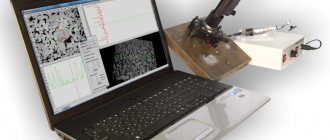
Passport for vertical drilling machine 2N150 / Drilling machines / Stanok-online.ru
Model, name: 2N150 Vertical drilling machine Manufacture: Sterlitamak Name, marking: 1. Operation manual 2N125.00.000RE 2. Materials for wearing parts 2N125.00.000RE, 2N135.00.000RE, 2N150.00.000RE 3. Certificate of container 2N125.00.000RE1 4. Materials for spare parts 2N125.00.000RE3 5. Electrical equipment 2N125.00.000RE, 2N135.00.000RE, 2N150.00.000RE Year: 1986 Pages: 136 Format: jpg
View sample documentation
Find out the cost of documentation
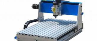
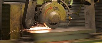
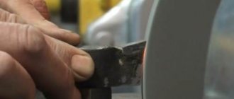
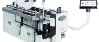
The universal vertical drilling machine model 2N150 is used in enterprises with single and small-scale production and is designed to perform the following operations: – drilling; – drilling; – countersinking; – countersinking; – deployment; – trimming ends with knives;
The presence of a mechanical spindle feed on machines, with manual control of work cycles, allows the processing of parts in a wide range of sizes from various materials using tools from high-carbon and high-speed steels and hard alloys. The machines are equipped with a device for reversing the main motion electric motor, which allows them to cut threads using machine taps using manual spindle feed. Placement category 4 according to GOST 15150-69.
Personnel allowed, in accordance with the established procedure at the enterprise, to work on the machine, as well as to set it up and repair it, are obliged to: - undergo safety training in accordance with factory instructions developed on the basis of the operating manual of standard labor protection instructions; – familiarize yourself with the general rules for operating and repairing the machine and the safety instructions contained in this manual, the operating manual for electrical equipment and the operational documentation attached to the devices and components included in the machine.
Transportation and installation of the machine. During installation, dismantling and repair, special holes in the column should be used for reliable mooring and safe movement of the machine. Lifting devices should be selected taking into account the machine weight specified in the “Installation Procedure” section of the manual. When transporting the machine, the drilling head is lowered to its lowest position and secured. To re-open the machine, you should follow the safety requirements in accordance with GOST 9.014-78. Preparing to start up the machine. Check the grounding of the machine and the compliance of the voltage in the network and the electrical equipment of the machine. Familiarize yourself with the purpose of all controls.
Check at idle speed of the machine: – operation of the mechanism and drilling head; – serviceability of signal, push-button and brake devices; – correct operation of locking devices; – serviceability of the lubrication system and cooling system; – the presence on the machine of rigid stops that limit the movement of the drilling head of the table;
stanok-online.ru
2N125, 2N135, 2N150. Universal vertical drilling machines [PDF]
Number of pages – 35. Contents: General information. Basic technical data and characteristics. Contents of delivery. Safety instructions. Composition of machines. Design and operation of the machine and its components. Lubrication system. The procedure for installing machines. Operating order of the machines. Possible malfunctions and methods for eliminating them. Features of disassembly and assembly when…
- 1.86 MB
- date added unknown
- modified 06/23/2018 06:25
Drawings: general view, convolution, development [compass], explanatory note: calculation of shafts, gears, bearings, belt drive [DOC].
- 570.93 KB
- date added unknown
- modified 06/23/2018 06:25
Catalog with a description of metal-cutting machines manufactured in Russia and the USSR. The files are named after the names of the machines. Each document is a machine passport (passport data) - a description of the machine, layout, overall dimensions, its technical characteristics.
- 94.06 MB
- date added unknown
- modified 07/02/2010 15:26
Drawing. The archive contains drawings of cutting tools made in Compass-3D - drills, countersinks, countersinks, cutters, cutters, broaches. The value of the archive is that you can find almost any type of cutting tool in it - 223 items in total. Note: The drawings are made without dimensions (only with dimension lines, i.e. when inserting into the drawing, the scale must be adjusted), without...
- 789.88 KB
- date added unknown
- modified 06.11.2017 20:11
Drawings: general view of the 16K20 machine, kinematic diagram of the 16K20 machine -3 drawings, kinematic diagram of the 6A54 milling machine, kinematic diagram of the 16K20F3 machine, development of the gearbox of the 16K20 machine, section of the gearbox of the 16K20 machine, tailstock of a lathe, tailstock of a special machine, k inematic diagram milling machine 6m82, kinematic diagram of the machine...
- 7.09 MB
- date added unknown
- modified 03/10/2011 19:26
A program for calculating allowances for machining, which, after entering the initial data, determines the allowance and tolerance parameters. Using the program, you can calculate allowances and tolerances for castings, forgings and rolled products.
- 293.28 KB
- date added unknown
- modified 09/10/2010 23:15
www.twirpx.com
Wiring diagram 2N150 | Passports for machines
DESCRIPTION OF THE ELECTRICAL DIAGRAM
General information
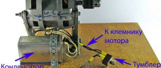
The electrical equipment of the machine includes a three-phase squirrel-cage asynchronous electric motor for rotation and working feed of the spindle, an electric cooling pump, and electrical control equipment.
The machine operates on alternating current voltage:
power circuit 3 phases 50 Hz or 60 Hz, 220 V, 400 V, 415 V, 440 V, 500 V;
control circuit—110 V; local lighting circuit—24 V;
signaling circuit—5 V.
The voltage of the power circuit, local lighting and alarm is determined by the customer.
Download Electrical diagram of drilling machine 2N150
The workplace is illuminated by a lamp with a flexible stand mounted on top of the electrical cabinet, with a switch and a low-voltage lamp L1.
On the front of the drilling head there is a built-in control panel for starting, reversing, swinging and stopping the main drive and a signal lamp L2, indicating the on state of the input switch. The supply wires and grounding are entered from below through a hole with a 3/4 pipe thread, which is closed with a plug or washer upon delivery.
The following controls are installed on the side wall of the control cabinet:
three-phase circuit breaker B1 with electromagnetic releases for connecting and disconnecting the supply network;
cam switch B2 for turning on and off the electric cooling pump.
It is necessary to periodically check the condition of the starting and relay equipment, and the tightness of the contact screws.
During the operation of electric motors, systematically carry out their technical inspections and preventive repairs. The frequency of technical inspections is set depending on production conditions, but not less than once every two months.
Download Electrical diagram of drilling machine 2N150
passportanastanki.ru
VERTICAL DRILLING MACHINE 2H150
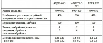
| The largest drilling diameter in steel is 45, mm | 50 |
| Spindle taper dimensions | Morse 5 |
| Distance from the spindle axis to the column guides, mm | 350 |
| Maximum spindle stroke, mm | 300 |
| Distance from the spindle end, mm | |
| to the table | 0-800 |
| to the stove | 700-1250 |
| Maximum movement of the drilling head, mm | 250 |
| Spindle movement per one revolution of the steering wheel, mm | 131,68 |
| Working surface of the table | 500x560 |
| Maximum table stroke, mm | 360 |
| Installation size of T-slots in the table | |
| central | 18N9 |
| extreme | 18N11 |
| Distance between two T-slots, mm | 100 |
| Number of spindle speeds | 12 |
| Spindle speed limits, min-1 | 22,4 -1000 |
| Number of innings | 9 |
| Feed limits, mm/rev | 0,5-2,24 |
| Highest number of holes cut per hour | 50 |
| Cycle management | Manual |
| Overall dimensions, mm | |
| height | 2930 |
| width | 890 |
| length | 1355 |
| Weight, kg | 1870 |
ekrpm.ru
Passport 2N150 (Ø 50 mm) Universal vertical drilling machine (Sterlitamak)
Name of the publication: Part 1: Operation manual (2N125.00.000 RE) – 25 pages Part 2: Materials on wear parts (2N125.00.000 RE), (2N135.00.000 RE), (2N150.00.000 RE) – 23 pages Part 3 : Certificate of acceptance (2N125.00.000 RE1) – 11 pages Part 4: Materials for spare parts (2N125.00.000 RE3) – 62 pages Part 5: Electrical equipment (2N125.00.000 RE), (2N135.00.000 RE), (2N150. 00.000 RE) – 15 pages Publication issue: Sterlitamak plant named after Lenin Year of publication: 1986 Number of books (folders): 5 Number of pages: 136 Cost: Negotiable Description: Complete set of documentation Contents: Part 1: Operation manual ( 2N125.00.000 RE) 1. General information – General view of the machines – Dimensions of the working space – Location of the components of the machines 2. Basic technical data and characteristics 3. Delivery set 4. Instructions for safety measures 5. Composition of the machines 6. Design and operation of the machine and its components – Location of controls and symbol plates – Kinematic diagram – Gearbox – Gear and feed switching mechanism – Feedbox – Drilling head – Spindle assembly 7. Lubrication system – Lubrication diagram 8. Machine installation procedure – Transportation diagram – Installation drawing – Installation diagram of the machines 9. Operating procedure of the machines 10. Possible malfunctions and methods for eliminating them 11. Features of disassembly and assembly during repairs 12. Operating instructions 13. Certificate of preservation 14. Certificate of packaging
Part 2: Materials for wearing parts (2Н125. 00.000 RE), (2N135.00.000 RE), (2N150.00.000 RE)*************
Part 3: Certificate of acceptance (2N125.00.000 RE1)
Part 4: Materials for spare parts (2Н125.00.000 РЭ3)************ Introduction - Bearing arrangement List of bearing arrangement diagrams Drawings of assembly units List of spare parts Drawings of spare parts
Part 5: Electrical equipment (2N125.00.000 RE), (2N135.00.000 RE), (2N150.00.000 RE) Description of the electrical circuit diagram General information – Electrical circuit diagram Operation of the electrical circuit diagram Instructions for installation and operation – Electrical connection diagram – Electrical diagram connections Table of wires to the connection diagram – Relay block electrical connection diagram Instructions for initial start-up
prompasport.ru