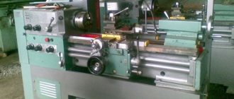
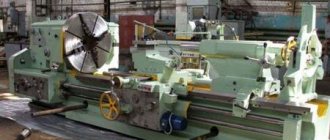
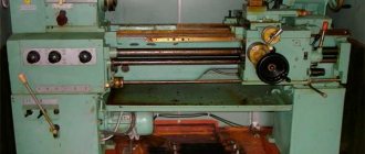
The TV-320 universal lathe, on which you can perform various technological operations for processing metal workpieces, belongs to the category of high-speed equipment, used primarily to equip tool and instrument-making enterprises.
Appearance of the TV-320 machine
The technical capabilities of the TV-320 lathe allow you to effectively perform the following technological operations on it: processing external as well as internal surfaces, turning cones, cutting metric threads, performing operational work, etc.
Machining on the TV-320 can be performed with a tool mounted on the front or rear tool holder. Such a mechanism is installed on the caliper if the need arises.
The characteristics of this unit allow processing using high-speed turning, as well as combining technological operations. The TV-320 design has a special mechanism with which you can change the feed parameters without stopping the machine.
There are several modifications of the lathe of the model in question, these include:
- TV-4;
- TV-6;
- TV-16.
How does the TV-320P machine differ from the equipment of the model in question?
The turning unit, which is marked with the letter “P”, differs from the basic TV-320 model by increased processing accuracy, which is ensured by the features of its design. There are increased demands on the manufacturing accuracy of the main structural components of the machine, which include its frame, lead screw, spindle assembly, front bearing and gears included in the kinematic chain used for thread cutting.
Such characteristics of the TV-320P lathe predetermine its use as equipment for performing semi-finishing and finishing work. This unit is not recommended for rough turning operations.
TV-320 controls
In order for the machine in question, which corresponds in its accuracy to the requirements of GOST 1969-43, to maintain its characteristics for a long time, the permissible feed speeds on it are reduced, as well as the maximum rotation speed of the spindle assembly - up to 1400 rpm (on the TV-320 machine this parameter corresponds to 2000 rpm).
Instructions for use
Turners characterize the TV 320 as a very reliable device. However, incorrect operation can lead to malfunctions and even breakdown of any equipment.
Before you start working, be sure to study the machine’s passport! The accompanying documentation contains complete information regarding:
- Purpose of the unit.
- Technical parameters.
- Sizes of cut threads by type.
There are also detailed diagrams of all components and control mechanisms.
About the design of the TV-320 machine
The design of the TV-320 lathe consists of the following elements:
- gearbox;
- feed switch box;
- headstock with spindle assembly;
- tailstock;
- a drive that ensures the execution of feeds;
- apron;
- cooling system drive;
- caliper carriage.
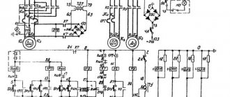
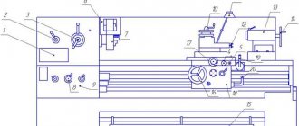
Kinematic diagram of the machine (click to enlarge)
Schematic diagram of the machine
TV-320 frame design
All structural elements that make up the TV-320 screw-cutting lathe are placed on a frame made of cast iron and has a box-shaped shape. Diagonal ribs in its inner part increase the rigidity of this load-bearing unit.
In the upper part of the equipment's supporting frame, mounted on two cast iron stands, there are three prismatic and one flat guides. The lathe slide moves along two of them (prismatic), and the tailstock moves along the other two (prismatic and flat). In the left cabinet of the frame there is a gearbox of the unit, a cabinet with electrical equipment, a motor responsible for driving the main movement, and a container for coolant.
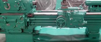
The bed of the TV-320 machine, prepared for grinding guides
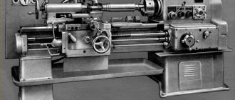
TV-4 (TV4) Training screw-cutting lathe. Purpose, scope
The TV-4 screw-cutting lathe replaced in production the obsolete first school screw-cutting lathes TVSh-2 and TVSh-3 (TV-3) and was produced in the 70s of the last century. The TV-4 machine was replaced by a more advanced model TV-6
The TV-4 lathe is an educational universal screw-cutting lathe and is intended for all kinds of turning work in workshops of schools for polytechnic training and cold metal cutting.
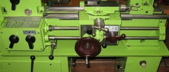
The educational screw-cutting lathe TV-4, despite its simplified design, has all the components of an “adult” screw-cutting lathe: spindle speed box, guitar, feed box, drive shaft and lead screw, caliper with mechanical feed.
The machine allows you to perform the following types of turning work:
- Grooving and boring of cylindrical and conical surfaces
- End trimming
- segment
- Metric thread cutting
- Drilling and a number of other works
Operating principle and design features of the machine
The front end of the spindle of the TV-4 machine has an M36x4 thread for installing an intermediate flange with a chuck (see the article Lathe chucks). The standard chuck for the TV-4 machine is Ø100 mm.
The spindle of the TV-4 lathe receives 6 stages of rotation (120, 160, 230, 375, 500, 710 rpm) from the gearbox in the headstock.
The gearbox, by switching gears, allows you to reduce the spindle speed required for tapping, as well as for heavy work that requires increased torque. Higher spindle speed is used for finishing work.
The machine is driven by an asynchronous electric motor ~220 V. Through a V-belt transmission and single-stage pulleys, the movement is transmitted to the input shaft of the gearbox. Inside the gearbox, movement is transmitted through gears to the spindle. The spindle, depending on the position of the handles on the headstock, rotates at one of 6 speeds. The direction of spindle rotation is determined by the motor.
From the spindle, the movement is transmitted to the output shaft of the gearbox, then to the guitar, and from it to the input shaft of the gearbox.
The feed box provides 3 caliper feed speeds and can cut 3 metric threads without rearranging gears in the guitar.
At the output of the feed box there is a lead shaft and a lead screw, which rotate alternately at one of 3 speeds.
The lead screw is turned on when threading. The speed of the lead screw is set by the handles on the feed box and determines one of the 3 metric threads (the lead screw can be used in longitudinal feed mode, but is not used so as not to wear it out). The direction of rotation of the lead screw is set by the left handle on the headstock.
The running shaft makes it possible to obtain one of 3 longitudinal feeds of the caliper. The feed speed is set by the handles on the front wall of the feed box.
The lead screw and lead shaft pass through the caliper apron, which converts the rotational movement of the lead screw or lead shaft into forward longitudinal movement of the caliper. Transverse mechanical movement of the support in the TV-4 machine is not provided.
Gearbox lubrication by spraying oil from the oil bath at the bottom of the headstock onto the gears. The feed box is lubricated with a wick from a tray, which is filled with oil once per shift. The apron, caliper, guitar, tailstock and bed are lubricated by hand once per shift.
Main technical characteristics of the school screw-cutting lathe TV-4
Manufacturer - Rostov-on-Don. The main parameters of the machine are in accordance with GOST 18097-93. Screw-cutting and turning machines. Basic dimensions. Accuracy standards.
- The largest diameter of a Disk-type workpiece processed above the bed is Ø 200, mm
- The largest diameter of the Shaft type workpiece processed above the upper part of the support is Ø 125 mm
- Distance between centers - 350 mm
- The longest turning length is 300 mm
- Electric motor power - 0.6 kW
- Full machine weight - 280 kg
Spindle of screw-cutting lathe TV-4
- Threaded spindle end - M36x4
- Spindle hole diameter - Ø 16 mm
- The largest diameter of the processed rod is Ø 15 mm
- Spindle speed limits per minute - (6 steps) 120, 160, 230, 375, 500, 710 rpm
- Standard chuck diameter - Ø 100 mm
The structure of the headstock of the machine
The headstock (spindle) of a lathe is made of cast iron. In its front part there is a gear selector mechanism, and in the rear part there is a feedbox drive mechanism that operates in forward and reverse directions.
The spindle of the unit is a hollow pipe, at the front end of which there is a conical neck. A plain bearing is installed in the front support of the spindle assembly, and a high-precision angular contact bearing is installed in the rear support. The cutting forces that act on the spindle assembly along its axis are absorbed by the thrust bearing.
Front spindle support with plain bearing
The spindle assembly elements must meet the following technical specifications:
- axial clearance between the elements of the rear support – 0.01–0.015 mm;
- runout in the axial direction – no more than 0.01 mm;
- the gap between the bearing and the spindle in the diametric direction is 0.015–0.03 mm.
Headstock drawing
The mechanism, which is used to change the direction of feed without changing the rotation parameters of the spindle assembly, is located in the headstock - on its left side. The rolling bearings of the headstock can be adjusted, for which special nuts are used.
How does the equipment support work?
The support of the TV-320 machine (as in any other turning equipment) simultaneously solves two problems:
- the cutting tool is fixed on it;
- This unit moves the turning cutter in two directions (longitudinal and transverse).
Support for lathe VT-320
The structural elements of the caliper are:
- cross slide;
- top slide;
- carriage (longitudinal slide);
- turning part.
The caliper carriage moving in the longitudinal direction, as well as the cutting slides, is driven manually and by a mechanical drive. An additional cutting head can be installed on the slide, for which two T-shaped grooves are provided in their design. The amount of transverse movement of the cutting slide is adjusted using two stops. In order to facilitate the calculation of the parameters of the transverse movement that the caliper makes along the limb, a ball stop is provided in the design of the latter.
Adjustable cross feed stop is convenient for serial processing of parts
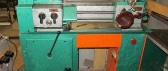
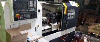
1M63D universal screw-cutting lathe. Purpose, scope
The 1m63d screw-cutting lathe (beginning of serial production in 1983) replaced the model. In 1986, the 1m63d machine was replaced by a more advanced model.
Screw-cutting lathes 163 series are one of the most widespread in the territory of the former USSR, designed for processing parts of medium and large sizes, in conditions of single and small-scale production. The machine can perform external and internal turning, including turning cones, boring, drilling and threading (metric, modular, inch and pitch).
Modifications of the 1M63 screw-cutting lathe
1M63 - the next generation of the 163 series, the machine replaced the 163 model, production began in 1968.
1M63F306 – CNC screw-cutting lathe, serial production began in 1973.
1M63F101 – a screw-cutting lathe with a digital display that provides a readout of the lateral movement of the support, serial production began in 1976.
1M63B, 1M63BG, 1M63BF101 – high-speed screw-cutting lathes with increased power.
1M63D, 1M63DF101 – screw-cutting lathes, Tbilisi, 1983.
1M63M, 1M63MF101 – screw-cutting lathes with increased power, Tbilisi, 1986.
1M63MF30 – CNC lathe Electronics NTs-31, Tbilisi.
1M63MS5 – screw-cutting lathe 163 series, Tbilisi, 1991.
Main technical characteristics of the 1M63D screw-cutting lathe
Manufacturer: Tbilisi Machine Tool Plant named after. Kirov.
The planned period for the installation series is 1983.
- The largest diameter of a Disk-type workpiece processed above the bed is Ø 630 mm
- The largest diameter of the Shaft type workpiece processed above the support is Ø 350 mm
- Distance between centers – 1400 mm
- Center height – 315 mm
- Electric motor power – 15 kW
- Total weight of the machine – 4.3 t
Spindle of screw-cutting lathe 1M63D
- Spindle end - according to GOST 12593 (Spindle ends are flanged for a rotary washer and clamping device flanges)
- Nominal cone diameter D = 139.719 mm, nominal spindle end size – 8
- Internal (tool) spindle cone – Morse 6
- The diameter of the through hole in the spindle is Ø 70 mm
- Limits of direct spindle revolutions per minute (22 steps) – 12.5..1600 rpm
- Limits of spindle reverse revolutions per minute (11 steps) – 22.4..2240 rpm
- Standard chuck diameter – Ø 400 mm
Feeds and threads of screw-cutting lathe 1M63D
- Limits of longitudinal feeds – 0.06..1.4 mm/rev
- Transverse feed limits – 0.024..0.518 mm/rev
- Feed limits of the cutting slide – 0.019..0.434 mm/rev
- Limits of metric thread pitches – 1..124 mm
- Limits of modular thread pitches – 0.25..56 modules
- Limits of inch thread pitches – 28..1/4 threads per inch
- Limits of pitches of pitch threads – 112..0.5 pitches
The technical characteristics and rigidity of the design of the machine bed, carriage, and spindle allow full use of the capabilities of working at high cutting speeds using cutters made of high-speed steel or equipped with carbide plates when processing parts made of ferrous and non-ferrous metals.
The machine support has a mechanical movement of the upper part, which allows turning long cones. Turning of short tapers is also carried out by moving the upper part of the support.
Changing the feed rates and adjusting the pitch of the thread being cut is carried out by switching the gears of the feed box and adjusting the set of interchangeable gears.
The support has rapid movement in the longitudinal and transverse directions, which is carried out by an individual electric motor.
Lathe designation
In 1937, ENIMS developed a type (nomenclature of types and sizes) of machine tools, including the adoption of a unified system of machine symbols.
1
– lathe (group number according to ENIMS classification)
M
– generation of the machine or designation of the manufacturer:
6
– subgroup number (1, 2, 3, 4, 5, 6, 7, 8, 9) according to the ENIMS classification (6 – screw-cutting lathe)
3
– height of centers above the bed (1, 2, 3, 4, 5) (2 – height of centers 315 mm)
Letters at the end of the model designation:
G
– a machine with a recess in the bed
A, M
– a machine with a mechanical drive of the upper (cutting) support. Available upon special order
B
– high-speed machine
D
- a machine manufactured by the Tbilisi Machine Tool Plant named after. Kirov
TO
– machine with copying device
P
– machine accuracy – (n, p, v, a, s) according to GOST 8-82 (P – increased accuracy)
F1
– a machine with a digital display device (DRO) and preset of coordinates
F2
– machine with CNC positional numerical control system
F3
– machine with contour (continuous) CNC system
Machine apron
The main purpose of the apron, which is located in the front part of the lathe, is to communicate the rotational movement of the lead screw and the lead roller to the support. The special mechanism with which the caliper is equipped eliminates the risk of simultaneous activation of the lead screw and roller, which protects them from premature failure. The inclusion of the uterine nut is associated with the position of the handle responsible for switching the feed of the TV-320. This activation can only be performed if this handle is in the middle position.
If overloads occur during processing, which may be due to an increase in cutting force or jamming of the cutting tool, the so-called falling worm mechanism is activated in the apron of the TV-320 machine, automatically turning off the feed.
Apron of the TV-320 machine
Safety and Precautions
Turning work always involves an increased level of risk. Key points of safety regulations:
- It is necessary to work only on fully functional equipment;
- Before starting the equipment, be sure to check the grounding and chip removal system;
- It is prohibited to lean on the machine or move away from it during operation;
- It is necessary to work in overalls and glasses.
The operator must also ensure that the oil does not splash and follow fire safety precautions.
The turning unit TV-320 and TV-320 P are designed to work in mass production conditions. They are distinguished by reliability and high performance, which is ensured by the design features of the equipment.
Structure of the gearbox
Using a gearbox, rotation from the main electric motor is transmitted to the spindle unit of the TV-320 lathe. There are two blocks of gears on the three shafts of the unit’s gearbox, providing 9 different spindle rotation speeds.
The gearbox housing can move along special grooves, which allows you to adjust the tension of the belts that transmit rotation to the spindle assembly. To move the box, you need to loosen the bolts that secure it to the guides. In order for the box shafts to successfully carry axial and radial loads, ball and roller bearings are installed in their supports, the gaps in which are adjusted using special screws and nuts.
Belts driving the spindle
The standard equipment of the machine allows you to cut metric threads. Other thread types require an additional set of gears, selected according to the table on the guitar cover.
Replacement machine gears
Description and design feature
The TV-320 unit is designed primarily for use in mass production conditions. All main components of the lathe and structure are located according to the classical scheme. A distinctive feature is the presence of a system for rapid turning of workpieces. There are also other features:
- it is possible to change the feed without stopping the equipment;
- the machine has an increased safety margin;
- The bed is made of high quality cast iron.
All this explains the high productivity and long service life of the TV-320 lathe
How the tailstock of the machine works
The tailstock of a lathe, which can only be moved longitudinally by hand, is used to support the right end of long workpieces during processing and to secure the cutting tool. The tailstock is secured to the frame using an eccentric mechanism.
Tailstock drawing (click to enlarge)
The tailstock can also move in the transverse direction, which allows processing of conical surfaces on the machine. A screw driven by a flywheel is responsible for the longitudinal movement of the tailstock along the frame guides. This screw is connected to a nut. The position of the quill, which moves inside the tailstock, is fixed by means of two clamping pins connected to the control handle.
Control diagram
The control diagram has:
- A handle that sets the rotation speed of the spindle assembly.
- Another handle that sets the rotation speed of the spindle assembly.
- A handle that sets thread cutting (right and left) and changes the direction of feed.
- A handle that sets the feed rate and thread pitch.
- A handle that switches the roller.
- Reversing button that turns the machine on and off.
- Lever protecting the cartridge.
- Availability of a protective screen.
- Handle securing the cutting head.
- Light source for illuminating the workplace.
- A handle that manually moves the cross slide.
- A handle that moves the upper (incisor) slide.
- The handle that secures the quill.
- A handle that secures the tailstock towards the bed.
- Flywheels that move the quill.
- A button that turns the rack and pinion gear on and off.
- Flywheels that manually move the longitudinal carriage.
- A handle that adjusts the nuts in the lead screw.
- A handle that includes the maximum mechanical gear.
- Protective shield in front of the lead screw and shaft.
- Availability of transformer OSZR-0.063–83UHL3.
Equipment
The machine assumes a basic configuration, discussed in detail below.
Cabinet
There is a front and rear cabinet.
The first has a U-shape and stiffening ribs in the lower and upper parts of the device.
The front cabinet has a reversing button on the body, which is responsible for turning the electric motors on and off.
There is a drive electric motor in the rear cabinet. It also has a U-shape, inside there is electrical equipment with a shield.
Feedbox and guitar replacement gears
An equally important element of the unit, the feed box and the guitar, their key features are discussed below:
- A set of interchangeable gears is used to change thread parameters.
- The feed box is driven by the gearbox using gears in the transmission mechanism, which includes:
- two shafts;
- five gears with different parameters;
- running roller;
- coupling;
- round nuts;
- shift handle;
- drain plug.
`
The handles on the feed box body determine the cutting parameters for workpieces. Another lever turns on the drive shaft of the unit.
Important! The feed box does not require special maintenance, only the presence of lubricant in the gear area for their full functioning
Headstock and tailstock
The main element of any machine is the headstock and tailstock. Their main features and purposes are listed below:
- The purpose of the headstock is to locate the spindle assembly with the gearbox.
- I use the tailstock to secure centers; they are used to support the end surfaces of large products. Thanks to the use of the center, it is possible to significantly increase the accuracy of work.
Also, through the headstock, access to the gearbox and guitar is provided, which allows you to adjust the cutting parameter.
Apron device
The apron is part of the device that houses the slide, which is responsible for the smooth movement of the caliper. It is made of steel.
The apron structure consists of:
- handwheel;
- rack and pinion gear;
- shaft;
- worm gear;
- uterine nut;
- running roller.
Caliper design
The support secures cutting tools for ease of processing and moves it while working with metal. Four carriages form the basis of the caliper design.
In the fourth carriage, the tool holder fixes the working tools. It moves towards the third carriage, but only longitudinally.
Rotary carriage No. 3 is attached to the second carriage, the latter, in turn, is attached to the first, moving transversely.
The caliper has its own characteristics:
- It securely holds the cutting tool.
- It is located in a certain position in relation to the workpiece.
- Can move in longitudinal and transverse directions.
The support significantly expands the functionality of the machine.
What technical capabilities does the machine of this model have?
Let's look at the technical characteristics of the TV-320 lathe.
- The distance between equipment centers is 500 mm.
- The maximum length of a part processed by turning is 500 mm.
- The maximum diameter of parts that can be processed on the machine: above the surface of the bed - 320 mm, above the surface of the support - 170 mm.
- The diameter of the through hole in the spindle assembly is 26 mm.
- The diameter of the rod that can be inserted into such a hole is 25 mm.
- The number of spindle rotation speeds is 18.
- The number of longitudinal and transverse feeds is 16 each.
- The machine spindle speed is 36–2000 rpm.
- Feed limits: longitudinal – 0.03–0.49 mm/rev, transverse – 0.012–0.18 mm/rev.
- The conical part of the spindle is made in the Morse-4 category, the quills are made in the Morse-3 category.
- Model dimensions (length, width, height): 1800x950x1250 mm.
- Equipment weight – 900 kg.
Technical characteristics of the TV-320 machine
Considering all the above characteristics, the capabilities of the TV-320 lathe are quite impressive, as evidenced by numerous positive reviews about this equipment.
Specifications
According to the passport, the TV-16 is a small-sized product, which is characterized by the following characteristics that allow the unit to be used in a small workshop.
Main settings
- maximum diameter of a disk-type part is 1.6 cm;
- maximum diameter of the workpiece - 0.9 cm;
- maximum length of the workpiece - 2.5 cm;
- the gap between centers is 25 cm;
- height of centers - 8.5 cm;
- The maximum groove height is 25 cm.
Spindle
Installing a lathe chuck on a spindle requires an intermediate flange.
Spindle parameters:
- front edge size - M 3.9*0.4 cm;
- instrumental shaft cone - 3;
- cartridge diameter - 10 cm;
- spindle hole diameter - 1.8 cm;
- parameters of axle revolutions per minute (6 stages) - 160, 250, 400, 630, 1000, 1600;
- maximum rod diameter - 1.7 cm;
- suspension - absent;
- reverse - in two directions.
Caliper and feed
The possibility of rotating the tetrahedral tool holder is 360 degrees with the rotation secured using the central handle at 45 degrees.
- axial movement per dial division - 0.5 mm:
- transverse movement per dial division - 0.05 mm:
- axial movement per one revolution of the dial - 32 mm;
- transverse movement per one revolution of the dial - 1.5 mm;
- number of cutters in the holder - 4;
- maximum axial movement – 2.6 cm;
- maximum lateral movement – 10 cm.
Cutting slide
The cross slide moves perpendicular to the axis of the machine, along guides located at the top of the carriage. The upper ones, together with the tool holder, follow the guides of the turning circle mounted on the transverse slide.
The movement of both slides occurs manually using nuts and screws.
- longitudinal movement of the limb per revolution - 3.2 cm;
- transverse movement of the limb per revolution - 0.15 cm;
- maximum rotation angle - 60 degrees;
- the value of one division of the rotation scale is 1 degree;
- maximum offset length - 1 cm;
- movement by one division of the limb - 0.05 mm;
- movement per one revolution of the dial is 1.5 mm.
Tailstock
- maximum displacement of the quill - 0.65 cm;
- tailstock lateral movement error ± 0.5 cm;
- lateral displacement error per 1 division - absent;
- Morse cone - 1;
- maximum displacement of the quill - 6.5 cm;
- the value of one division of the quill displacement: ruler 1 mm, quill - 0.5 mm.
Electrical equipment
An electrical equipment unit consists of several mechanisms working together to turn the device on and off. As well as ensuring safety during short circuits and voltage surges in the network, blocking in emergency cases and grounding the machine.
Includes: a reversing type packet switch that connects the machine to the network, a fuse, a magnetic starter that starts and stops the unit, and a “Stop” button.
- engine power - 0.4 kW;
- Mains voltage: 220–380 V.