Technical characteristics of the machine 165
Technical characteristics of the machine 165 are the main indicator of the suitability of the machine for performing certain jobs on the machine. For screw-cutting lathes, the main characteristics are:
- The largest diameter of the workpiece
- Distance between centers
- Maximum length of the processed product
- Spindle revolutions per minute
Below is a table with the technical characteristics of the screw-cutting lathe 165. More detailed technical characteristics of the machine can be found in the passport of the machine 165 located below.
Attention! The technical specifications given in the above table are for reference only. Machines produced by different manufacturers and in different years may have characteristics that differ from those given in the table.
Electrical diagram of a screw-cutting lathe model 165
Wiring diagram of universal screw-cutting lathe 165
Electrical equipment of machine 165. General information
The following electric motors are installed on the machine:
- main drive motor
- electric motor for rapid movements of the carriage
- cooling pump motor
The electrical equipment of the machine is powered from an alternating current network of 380 V, 50 Hz.
The 24 V DC control circuits are powered from a selenium rectifier D1 (single-phase bridge, see Fig. 14).
The 110 V AC control circuits are supplied from a step-down transformer.
The 24 V local lighting lamp is powered from a separate transformer.
All control equipment for the electric drives of the machine is mounted in the niche of the headstock and is listed in table. eleven.
The electric drives of the machine are controlled remotely, using push-buttons, and are carried out (see Fig. 17):
- from the control panel on the front headstock - PB
- from the control panel on the carriage - PC
- from the control panel on the apron - PF
The electrical equipment of the machine is connected to the workshop electrical network using an input circuit breaker (automatic switch) BA1 installed on the side wall of the headstock niche. The input is carried out with a wire with a cross-section of 10 mm2.
Protection of electric motors and control circuits from short circuit currents and overloads is carried out by automatic switches and thermal relays.
The values of rated currents and values of inserts of magnetic starters and relays are given in table. 12, 13.
Zero protection of the electrical equipment of the machine is carried out by opening the circuit. (closing) block contacts in the self-supply circuit of magnetic starters and relays when voltage disappears in the workshop electrical network.
Machine passport 165
This operating manual ( Machine Passport 165 ) contains information necessary both for the maintenance personnel of this machine and for the employee directly involved in working on this machine. This manual is an electronic version in PDF format of the original paper version.
CONTENT
Purpose and scope of the machine
Unpacking and Transport
Machine foundation, installation, installation
Technical data sheet of the machine
- Basic data
- Caliper
- Tailstock
- Additional data
- Drive unit
- Friction couplings
- Specification of the main groups of the machine
- Control Specification
- Specification of gears, worms, worms, screws and nuts
- Main movement mechanism
- Feed mechanism
- Replaceable gears
- Feed mechanism
- Pumps
- Changes to the machine
- Major repairs
- Specification of accessories and accessories
Brief description of the rate
- bed
- Headstock
- Tailstock
- Caliper and carriage
- Apron
- Gearbox
- Guitar
- Cartridge
- Lunettes
- Cooling
Electrical equipment of the machine
- General information
- Description of the electric drive and control circuit
- Turning on and off the electrical equipment of the machine
- main drive
- Feed drive
- Cooling drive
- Maintenance of machine electrical equipment
- Possible malfunctions of the electrical equipment of the machine and measures to eliminate them
- Electrical Specification
Machine lubrication
- Specification for the machine lubrication scheme
- Maintenance instructions and brief description of the machine's lubrication system
Preparing the machine for initial start-up
Safety precautions
- Technical safety features provided in the machine design
- Safety rules for operating the machine
Machine adjustment
- Adjusting the spindle bearings
- Adjusting the apron safety clutch
- Adjusting the clearance in the guide of the upper and lower halves of the lead screw nut
- Layout of electromagnetic coupling fittings and adjustment
- Adjusting the tension of the main engine belts
Specification of rolling bearings and the most important plain bearings
Specification of wearing parts
- Symbols printed on machine tables
- Acceptance certificate for universal screw-cutting lathe
download the passport of the screw-cutting lathe 165 in good quality using the links below.
Machine passport 165. Option 1. Download for free. Machine passport 165. Option 2. Download for free.
Brief description of the 165 screw-cutting lathe
bed
The bed is the basic assembly unit on which all other assembly units and mechanisms of the machine are mounted.
On the top of the frame there are three prismatic guides, of which the front and rear are the base of the carriage, and the middle one is the base of the tailstock.
Inside the frame there are inclined hatches for removing chips and coolant in the direction opposite to the workplace.
Under the left head part of the frame there are niches, in one of which the main drive electric motor is mounted, and in the other - an electric cooling pump with a coolant reservoir. The trough for collecting coolant is made monolithic with the frame body.
On the right side of the frame, on the front wall, there is mounted a bracket with built-in supports for the lead screw and the drive shaft and a fast-moving gearbox for the caliper with a flange electric motor.
To prevent sagging of the lead screw and the lead shaft, the machine with RMC 5000 has two suspensions.
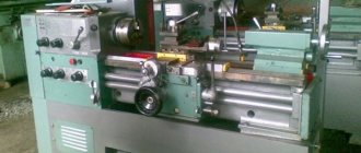
Front headstock of screw-cutting lathe model 165
Front headstock of screw-cutting lathe 165
The front headstock is installed on the left head part of the frame, fixed with pins and secured with bolts.
The following are mounted in the headstock housing:
- gearbox
- spindle unit
- eight-fold step increase link
- mechanism for changing the direction of movement of the carriage when cutting threads
- spindle speed adjustment mechanism
- Lubrication system
- electrical cabinet
The spindle is mounted on three rolling bearings, of which the front and rear are adjustable.
A description of the adjustment of spindle bearings is given in the “Adjustment” section.
Adjustment of the spindle rotation speed, as well as adjustment for cutting right or left threads of normal or increased pitch is done by moving the gears along the splined shafts using handles located on the front wall of the front headstock (see Fig. 37 and Table 22).
The shaft splines and gear teeth are hardened and ground.
Enabling the step increase link is possible only when working with brute force.
Tailstock
The rear headstock moves along the frame guides from the manual gearbox by rotating the roller 26 (see Fig. 3).
The headstock is attached to the frame using two clamps with three bolts.
For rigid fixation in the axial direction, there is a stop in the rear headstock, which can be inserted into the cast cavities of the frame using handle 27.
The headstock body moves along the bridge in the transverse direction (see subsection “Regulation”).
A rotating spindle is built into the headstock quill, the front support bearings of which are adjusted using nuts.
Rapid movement of the quill is carried out by the flywheel 29. Locking is carried out by the handle 33.
Slow movement of the quill is carried out by handles 31 through a worm gear, activated by handle 30.
For drilling, countersinking and reaming, by turning the pusher 28, it is necessary to turn on the gear coupling, which rigidly connects the spindle to the quill.
The tailstock spindle has a slot for the legs of the tail cutting tool.
When changing the center or tool, the quill must be pushed into the headstock body as far as it will go. In this case, the pusher pushes the center or tool out of the spindle.
Caliper and carriage
The cross-design support has longitudinal movement along with the carriage along the frame guides and transverse movement along the carriage guides. Both movements are carried out mechanically (with working feed and using a quick movement mechanism) and manually.
The cutting slide, carrying a four-position tool holder, is moved manually along the guides of the rotating part, which can be rotated around a vertical axis to any angle.
The nut of the screw pair for the transverse movement of the caliper is composite and separated by an adjusting wedge. The adjustment of the gaps in the guides of the carriage, the rotating part, made by wedges, in the screw pair of the transverse movement of the caliper is given in subsection 2.4. "Regulation".
Machine apron
The apron is a closed type with a removable front wall (lid).
The movement of the caliper group is transmitted by the apron mechanism from the drive shaft or lead screw.
Due to the presence of four electromagnetic clutches in the apron, control of the mechanical movement of the support group is concentrated in one handle 23 for controlling the mechanical strokes of the carriage and support (see Fig. 3), and the direction of activation of the handle coincides with the direction of feed.
By additionally pressing button 24 (see Fig. 3), built into handle 23, you can turn on the rapid movement of the caliper in the direction of tilting the control handle (23).
Thanks to the overrunning clutch built into the feed box, high speed can be activated when the feed is on.
The lead screw nut is split and is activated by handle 21 through a cam device.
To prevent simultaneous activation of the lead screw nut and the feed, there is an electromechanical lock.
A safety clutch mechanism is mounted in the apron, which prevents the machine from breaking due to overload. Its adjustment is given in subsection 2.4. "Regulation".
Gearbox
The feed box is a closed type with a removable front wall (lid).
The feed box mechanism allows you to get all the feeds and threads cut on the machine without having to change the settings of the replacement gears.
Set up the feed box for feeding or threading in accordance with table. 23 and 24 in the following order (see Fig. 3 and Fig. 38):
- move handle 10 to the “off” position
- move handle 14 to the “lead screw” position for cutting threads or to the “lead roller” position - to work with feed
- move handle 7 to one of three positions - “inch thread”, “modular thread”, “metric thread or feed”
- install handles 9, 12, 13 according to the table of feeds and threads on the required thread or feed, and to install handle 9 in the desired position, place the corresponding number on its disk under the pointer;
- move handle 10 to the “on” position
When setting up for cutting threads with a pitch of increased precision, connect the lead screw with gear couplings directly to the receiving shaft of the feed box in accordance with Table. 25 (see Fig. 39).
Replacement gears
A set of replaceable gears with icm = 2/3, which makes it possible to obtain on the machine all the threads and feeds specified in the “Passport” section, is installed on the wall of the front headstock.
The design of the interchangeable gear mechanism provides for the possibility of installing other sets of gears.
Ammo
The machine includes a four-jaw non-self-centering chuck with a diameter of 1000 mm.
Lunettes
For processing non-rigid parts, the machine is equipped with two steady rests - movable and fixed.
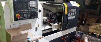
Screw-cutting lathe DIP-500 (1M65)
The DIP-500 screw-cutting lathe began to be produced instead of the 165th line lathe. With its help, it became possible to process large-sized workpieces in small-scale and individual production. Due to its high reliability and quality of manufacture, the machine was exported.
Today, these models are not produced, but you can choose their modern analogues.
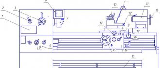
Kinematic diagram of a screw-cutting lathe model 165
Block diagram of lathe 165 (with kinematic diagram 2)
Kinematic diagram of screw-cutting lathe 165
Bearing layout for screw-cutting lathe 165
The main movement is driven by an electric motor through a V-belt drive.
The gearbox provides the spindle with 24 different speeds of both forward and reverse rotation through kinematic chains according to table. 4.
The spindle is reversed by an electric motor.
Rotation is transmitted to shaft IX of the gearbox from the spindle through gears 21-22, 26-27 or from shaft V (when the step increase link is turned on eight times) through gears 16-24, 23-22, 26-27. Ball IX receives one or eight revolutions per spindle revolution, respectively.
The block of gears 25 and 28 is designed to change the direction of movement of the carriage when cutting threads.
The movement is transmitted to the feed box from shaft IX through replaceable gears 30-32-31.
The feed box communicates to the caliper through the overrunning clutch, the XXIII running shaft and the apron mechanism 32 longitudinal and transverse feeds.
The kinematic chain of longitudinal and transverse feeds is calculated using the formula
i = icm * ik.p * if
Where:
icm is the gear ratio of replaceable gears;
ik.p - gear ratio of the feed box;
if is the gear ratio of the apron.
The kinematic chains through which feeds are carried out are given in table. 5 for the feed box and in the table. 6 for the apron.
Threading is carried out through the kinematic chains of the feed box, given in table. 7. In addition, threading can be done by directly connecting the lead screw with replaceable gears, selecting the appropriate icm (see Table 24). The range of feeds and threads is expanded when using an eight-fold pitch increase link.
The list of elements of the kinematic scheme (see Fig. 4) is given in table. 8, and the corrected gears - in Table 9.
Model designation
In the marking of the screw-cutting lathe DIP-500: DIP means the above slogan, and 500 is the value of the height of the centers above the bed - 500 millimeters.
Download the passport of the lathe 1M65 (DIP-500)
In the marking of ENIMS (Experimental Research Institute of Metal-Cutting Machine Tools), model 1M65 stands for:
1 is the designation of the group number of lathes;
M is a designation for the modernization of the base model;
6 is the designation of the machine type;
5 is a designation of the main characteristic of the machine model - the height of the centers above the bed is 500 millimeters.
Lathes
Purpose
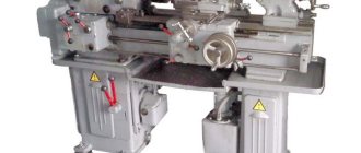
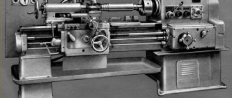
Screw-cutting lathe 165 is designed for processing cylindrical, conical and complex surfaces - both internal and external, as well as for cutting threads. To process the end surfaces of workpieces, a variety of cutters, reamers, drills, countersinks, as well as dies and taps are used.
Designation
The alphanumeric index of the screw-cutting lathe 165 means the following: number 1 is a lathe; number 6 – indicates a screw-cutting lathe, number 5 – height of the centers (500 mm).
| Technical characteristics of the machine 165 | Options |
| Largest processing diameter above the bed, mm | 1 000 |
| Machining diameter above the support, mm | 650 |
| Distance between centers | 3 000 — 10 000 |
| Headstock spindle end size according to DIN | 2-15M |
| Diameter of cylindrical hole in spindle, mm | 128 |
| Number of spindle speed steps | 24 |
| Spindle speed limits, rpm | 5 — 500 |
| Accelerated longitudinal movement of the caliper, m/min | 3 |
| Accelerated lateral movement of the caliper, m/min | 1 |
| Main drive motor power | 22 kW |
| Maximum weight of the workpiece in centers, kg | 8 000 (10 000) |
| Overall dimensions of the machine (L x W x H), mm | 6,140 - ... x 2,200 x 1,770 |
| Machine weight, kg | 12 800 — … |
mzorinvest.ru
Description
The DIP-500 machine is a turning equipment that is universal; it can be used in various fields of industry for turning operations for manufacturing products. With its help, it is possible to perform the above work with normal accuracy (H) and high productivity. Over the entire period of operation, the machine has proven itself to be highly reliable due to the quality of manufacture and ease of maintenance, and also did not require high attention or special conditions during operation.
Kinematic diagram of machine 165
A sketch of one sheet “ Kinematic diagram of machine 165 ” is shown in the following figure:
download the kinematic diagram of the screw-cutting lathe 165 in good quality from the link below.
Kinematic diagram of machine 165. Download for free.
You can view additional information on “Machine 165” using the link below:
Search the site on the topic “Machine 165”
Design of sectional horizontal pump CNS 60-165
The main structural units of the pump are the casing and the rotor.
The housing includes suction and discharge line covers, guide vanes, front and rear brackets. The housings of the guide vanes, suction and discharge covers are tightened with coupling bolts.
The guide vane, ring (with sealing rings) and impeller form the pump section. The joints of the guide vane housings are sealed with rubber rings made of oil- and petrol-resistant rubber.
Due to the fact that the pump body consists of separate sections, it is possible, without changing the flow, to change the pressure by installing the required number of impellers and guide vanes with housings. In this case, only the length of the shaft and tie rods changes.
The pump rotor consists of a shaft on which impellers, a ring, a shaft jacket, a spacer sleeve, adjusting rings and a relief disk are installed. All parts on the shaft are tightened with a rotor nut.
The rotor is supported by two radial spherical bearings installed in the front and rear brackets in a sliding fit, allowing the rotor to move in the axial direction by the amount of the rotor “run-up”.
The bearing chambers are sealed with cuffs installed in the bearing caps.
The bracket is closed from the outside with a cover in which a rotor displacement control device is mounted.
Design Features
Any machine includes some standard components. They determine what functionality a particular type of equipment has.
bed
The bed acts as a load-bearing element. The remaining parts are attached to this part. Structurally, this part looks like two walls that connect to each other. Rigidity to a certain extent is given to it by the transverse elements that organize the connection. The machine is equipped with separate parts that move along the bed.
To solve this issue, special guides are provided.
- Three of the guides have a prism-shaped cross-section.
- One part is flat.
Headstock
The headstock is needed to simultaneously perform two functions:
- The workpiece is fully supported while processing is in progress.
- So that the part rotates in a certain way.
The front part of this equipment also contains handles responsible for controlling speeds. Thanks to this, the spindle can rotate at a certain frequency.
A special diagram is usually placed next to the handle. It is enough to study it once to understand when and what part is turned on.
The headstock in front houses a high-speed box, complemented by a rotating spindle assembly. Inside this part of the structure, special bearings can be used for rolling or sliding. The chuck of the device is fixed at the end of the spindle; a connection with threads is necessarily used in the process. This unit ensures that the part rotates in a certain way while processing is in progress.
To move the carriage on the machine, bed guides with a prismatic cross-section are used. This part must maintain certain properties such as accuracy and straightness. Neglecting such conditions will not allow you to get quality work in the end.
Operating principle of the sectional horizontal pump CNS 60-165
The operation of the pump is based on the interaction of the rotating impeller blades and the pumped liquid.
Rotating, the impeller imparts a circular motion to the fluid located between the blades. Due to the resulting centrifugal force, the liquid from the center of the wheel moves to the external outlet, and the vacated space is again filled with liquid coming from the suction pipe under the influence of the created vacuum.
Having left the impeller of the first section, the liquid enters the channels of the guide vane and then into the second impeller with the pressure created in the first section, from where it enters the third impeller with increased pressure created in the second section, etc.
The liquid released from the last impeller flows through the guide vane into the discharge cover and from it into the discharge pipeline.
During pump operation, due to water pressure on the unequal area lateral surfaces of the impellers, an axial force arises, which tends to displace the pump rotor towards the suction side.
To balance the axial force, the pump is equipped with an unloading device, consisting of an unloading disk, an unloading ring and bushing, and a spacer bushing.
The liquid from the last stage passes through the annular gap between the unloading bushing and the spacer bushing and presses on the unloading disk with a force equal to the sum of the forces acting on the impellers, but directed towards the discharge. The pump rotor is balanced, and equal forces are established automatically.
The liquid leaving the unloading chamber cools the oil seal on the pressure side.
The suction side seal is flushed with liquid supplied under pressure from the suction line. The liquid, passing through the shaft jacket through the stuffing box, prevents air from being sucked into the pump and at the same time cools the stuffing box. Most of the liquid passes through the gap between the shaft jacket and the hydraulic seal sleeve into the suction cavity, some passes between the shaft jacket and the oil seal on the suction side, cooling it, the rest comes out through the fitting.
The tightening of the stuffing box should allow the pumped liquid to leak out between the shaft and the stuffing box packing in an amount of 5-15 l/h. A smaller number indicates that the oil seal is over-tightened, which increases friction losses and accelerates wear of the shaft jacket and rotor nut.
The pump rotor is driven by an electric motor connected to the pump through an elastic sleeve-finger coupling, consisting of two coupling halves (pump and electric motor) and fingers with rubber bushings.
The direction of rotation of the pump rotor is clockwise when viewed from the electric motor.
The pump and electric motor are installed on a common foundation plate so that there is a gap of 10 mm between the coupling halves when the pump rotor is shifted completely towards the suction side.
The unit's electric motor must be grounded before operation.
The CNS pump has self-priming capabilities. This condition is achieved by installing a valve inside the pump.
As part of the central nervous system pumping unit, as a rule, general industrial asynchronous electric motors are installed on the pump. Most often, a three-phase asynchronous motor with a squirrel-cage rotor is used for these purposes.
Pumps are manufactured with both stuffing box and mechanical seals. Leaks through mechanical seals - according to the technical documentation for mechanical seals.
The pump support brackets are made of cast iron, the material of the flow part of the pumps is TsNS SCh-20, Steel 35L, the shaft is steel 40x, the guide vane, ring and body of the guide vane, the oil seal bushing is made of press material AG-4V. The pump shaft is sealed using an stuffing box packing with a cross-section of 10 mm.
CNS pumps operate stably and for a long time with a headwater of 2-6 m. In the absence of headwater at the inlet, cavitation quickly destroys these high-speed pumps. When installing them to pump water with a temperature of more than 45°C, it is necessary to increase the pressure at the inlet to the pump.
Rice. Graphic Characteristics of pumps CNS 60-165
tested in water, density 997 kg/m3
at a rotation speed of 2950 rpm
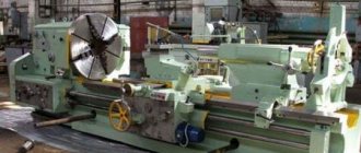
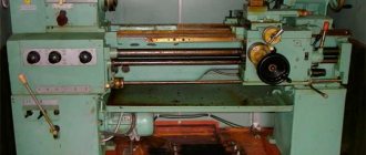
Universal screw-cutting lathe 165 (RMC 5000)
Price as of January 28, 2018 - request price
| Buy | Add to comparison |
The 1N65-5 screw-cutting lathe is designed to perform a variety of turning operations, including turning cones and cutting threads: metric, inch, modular, pitch.
High drive power and rigidity of the machine, a wide range of spindle speeds and feeds allow you to fully utilize the capabilities of advanced tools when processing various materials.
Design Features
- rigidity, vibration resistance and temperature stability of the structure allow obtaining the necessary processing accuracy;
- 2-prism guides of the frame in combination with the high reliability of other components ensure a long service life of the machine while maintaining the original accuracy;
- the frequency of reverse spindle rotation is 1.3 times higher than direct rotation, which reduces the thread processing time;
- turning long cones is carried out by simultaneous longitudinal feed of the support and feed of the cutting slide with their corresponding rotation;
- The feed box has a high rigidity of the kinematic chain, has 2 electromagnetic clutches for remote switching of feeds without stopping the machine;
- all power gears of the kinematic chain are made of alloy steel, hardened and ground;
- guards for the cutting area and chuck, electrical and mechanical interlocks guarantee safe operation of the machine.
Technical characteristics of screw-cutting lathe mod. 1N65-5 Characteristic Meaning
| The largest diameter of the workpiece to be installed and processed, mm: | |
| above the caliper, mm | 650 |
| above the recess in the frame, mm | 1400* |
| Maximum length of workpiece processed, mm | 5000 |
| Length of the recess in the frame from the chuck mirror, mm | 390 |
| Headstock spindle end size according to DIN | 2-15M |
| Number of spindle speed steps | 24 |
| Diameter of cylindrical hole in spindle, mm | 128 |
| Spindle speed limits, rpm | 5 — 500 |
| Limits of working feeds, mm/rev.: | |
| longitudinal, mm/rev | 0,06 — 2,42 (0,6 — 19,36***) |
| transverse, mm/rev | 0,022 — 0,88 (0,022 — 7,04***) |
| cutting slide, mm/rev | 0,022 — 0,88 (0,022 — 7,04***) |
| Limits of pitches of cut threads: | |
| metric, mm | 1 — 96 |
| inch, threads/inch | 24 — 0,25 |
| modular, module | 0,5 — 24 |
| pitch, pitch dia. | 96 — 1 |
| Accelerated movement of the caliper, m/min: | |
| longitudinal | 3 |
| transverse | 1 |
| Main drive power, kW | 15 |
| Maximum weight of the workpiece in centers, kg | 10000,8000* |
| Main drive power, kW | 22 |
| Weight 165 (RMTs 5000) 1N65-5, kg | 15750 |
| Dimensions: | |
| length, mm | 8180 |
| width, mm | 2200 |
| height, mm | 1770, 1880 |
rustan.ru