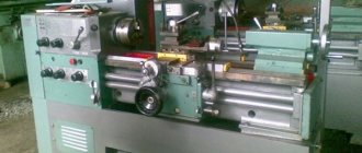
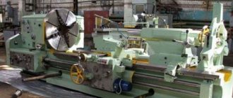
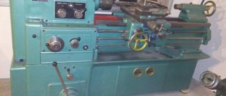
The rooms equipped for labor training classes in the country's secondary schools, vocational and technical schools and colleges are equipped with a metal-cutting lathe - TV-7.
Its direct purpose is to provide qualified training to future personnel of manufacturing enterprises in the working profession - turner.
Specifications
The new device was obtained as a result of the modernization of the TV-6 machine. It differs from the previous one in the presence of a gearbox, a shaft that serves to transmit force from the electric motor to the workpiece. The device allows you to check the alignment of the part with its axis of rotation.
Description of the main distinguishing features:
- classification according to the accuracy of thread manufacturing - “N”;
- weight – 40 kg;
- dimensions – 105x53.5 cm and 105x120 cm;
- distance from the frame to the central part – 120 mm;
- the length of the blank fixed in the central part is 330 mm, the same in the cartridge - 310 mm;
- blank grooving distance – 300 mm;
- length of movement of the cutter slide – 85 mm;
- the chord of clearance of the main shaft passing through the inside of the part is 18 mm;
- the period of rotation of the part around the axis is 8;
- the degree of repetition of torsion of the main shaft head is 60-1000 rpm;
- the diameter of the blank, which is fixed above the device body – 220 mm, the tool holder – 100 mm;
- height of the device holding the cutter – 16x16 mm;
- tool holder movement distance – 260 mm;
- longitudinal and transverse adjustment of the tool holder according to the limb layout - 0.025 mm;
- the value of the tool holder approach period is 8;
- The rotation angle of the slide where the cutter is installed is +/- 45.
The equipment is equipped with elements that protect against damage from chips - a shield, a transparent screen.
The first is installed above the chuck, and the second is on the caliper. It is lowered over the area in which the part is being processed.
Exploitation
The operating instructions draw attention, first of all, to the need to comply with safety measures. Basic Rules:
- Install the equipment on a rigid foundation; check the level of the installation with a level. The accuracy of the work largely depends on correct installation;
- reliably ground the machine in accordance with the requirements;
- use a wooden lattice as a stand;
- fasten the workpieces securely;
- use cutters with proper sharpening;
- secure the part in the chuck so that the cams grip it to the maximum possible extent;
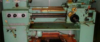
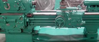
Cartridge, the guides are clearly visible in the photo
- do not screw the cartridge by sudden braking;
- fasten in the chuck without emphasis on the center of the rear centered parts no more than two diameters long. For longer lengths, use the center;
- Having installed the parts in the centers, check the fixation of the tailstock;
- remove shavings in a timely manner using a crochet hook.
Machine care
For reliable and durable operation, the following rules must be followed:
- Before making switches, the machine must be completely stopped. If the gear pair does not engage or the gear clutch does not engage, turn the chuck by hand until the gears or clutch engage. Switching when the machine is not completely stopped leads to impacts, which causes rapid wear and breakage of gears and couplings.
- When installing the cartridge, clean the threads. Contaminated threads lead to chuck jamming and spindle breakage.
- Caliper seals require maintenance. Chips gradually accumulate in them, which damages the guides.
- Make sure that after the caliper there is no dirty mark on the guides. If a dirty mark becomes noticeable, it is washed off and the guides are lubricated with clean oil.
- The machine should not be overloaded. Overload causes increased noise, belts slip, bearings and the electric motor overheat.
- If the part is machined in the centers, the quill is extended to the smallest amount: the fastening will be secured more firmly, and the quill will last longer.
Lubrication
Timely lubrication guarantees trouble-free, long-lasting operation. Rubbing parts, screws, shafts, gears, bearings are subject to lubrication. The following components are lubricated:
- Headstock through the top cover. An oil level indicator is used to control the level.
- Reducing box through a plug. An oil level indicator is used to control the level.
- Feed box through the tray at the top. From there it is fed through wicks to the rubbing surfaces and gears. There should always be some oil in the trough. The accumulated oil is drained through the plug from below.
- Guitar: Grease is used to lubricate the gears and bushing.
- On the bed, all mechanisms, bearings, and guides are lubricated manually before starting work.
- Everything in the apron is lubricated through the hole at the bottom of the caliper. Lubrication is carried out every time before starting work.
- Everything in the caliper is lubricated by hand before work.
- Tailstock. Lubricate the quill and the screw support before work.
Types of work performed on the machine
On the TV-7, 7m machine the following is produced:
- cutting alternating protrusions and depressions on the surface of parts located along a helical line;
- complete separation of a certain part of the workpiece along an open contour;
- expansion of gaps in large and small metal objects with preliminary shapes in accordance with given dimensions;
- grinding surfaces to give the shape of a cone or cylinder;
- drilling through or blind cylindrical holes;
- trimming the end parts of future parts.
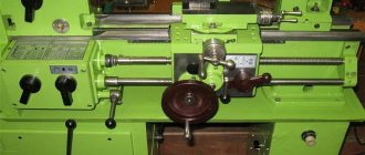
Operating principle and basics of proper operation
Making something on such a machine is very simple. Due to its small dimensions, relatively simple design and meager list of work that can be performed, compared with more expensive devices. You can learn to work with them in literally 5 minutes.
The diagram of their actions is as follows: there are holes in the tailstock, tools that are needed for a specific task are attached there. Thanks to the guides, it is always movable, depending on the length of the parts, it is installed in different positions.
And the carriage itself is responsible for the mobility of the working tool; it is installed on guides:
Working with a machine may be easy, but very dangerous.
And before using it, you need to follow some rules. All body movements should be smooth, without sudden manipulations. Before turning it on, you need to check that all parts are covered with factory protection, and that there are no various objects lying on the machine elements. Be sure to make sure that the switches and handles are in the neutral position. Pay special attention to how the workpieces and cutting tools are secured so that they do not fly out at high speed. Under no circumstances should you remove chips with your hands, but rather with brushes, hooks or chip breakers. Make sure that your work cannot harm someone or yourself.. A school lathe is a very necessary thing on the farm.
It is simple in design, reliable and small. And purchasing such a device will certainly bring a lot of benefits.
A school lathe is a very necessary thing on the farm. It is simple in design, reliable and small. And purchasing such a device will certainly bring a lot of benefits.
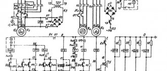
Electrical equipment
The electric motor and reduction gearbox are mounted in a cabinet located on the left side. Their shafts are equipped with 4 pulleys, which have different diameters. They are arranged in ascending order from smallest to largest - at the engine, and vice versa at the box body.
Electrical equipment consists of:
- asynchronous motor with a power of 1.1 kW, which is mounted in the left pipe;
- shield installed in the cabinet on the right side. Mounted on it are a switch, a starter, a fuse and an emergency switch;
- a cam switch located at the rear of the frame;
- power buttons and lighting devices installed on the side.
Tailstock and guitar
The tailstock is an important part of the lathe, which is used to support one of the ends of the workpiece. It is also necessary for securing certain tools - drills, taps, reamers and many others.
The tailstock has a housing. It is capable of moving in several directions, depending on the assigned tasks. The design of this element includes a conical mounting hole. It is designed to secure a chuck or conical center.
There is also a guitar in the design of the lathe. It is capable of transmitting rotational motion from the spindle to the gearbox.
Analogs
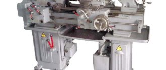
An analogue of the TV-7 machine is its improved model - TV-7m, manufactured by the above-mentioned plant in a desktop version.
Features:
- main dimensions of the model – 1120x640 mm, 1120x680 mm;
- electric motor performance – 750 W;
- the maximum distance for moving the headstock quill located at the rear is 65 mm;
- The diameter of the manufactured parts when they are fixed above the device body is 220 mm. The same above the caliper – 100 mm;
- length of the processed element installed in the central part – 275 mm;
- processing length of the part installed in the chuck – 250 mm;
- the height of the device serving as a holder for the cutter is 16x16 mm;
- maximum weight of parts to be processed – 5 kg;
- spindle head clearance diameter – 18 mm;
- the number of stages of rotation of the workpiece around the axis of the main shaft is 6.
In order to simplify the design, the TV-7m machine is equipped with several pairs of gears with different gear ratios. They, together with the shafts, convert the torque to a given parameter.
The following operations are performed on it:
- boring and grooving of surfaces of various shapes;
- cutting, drilling, trimming parts;
- trimming, cutting external and internal threads;
- grinding of manufactured parts.
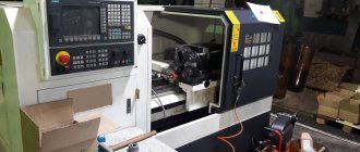
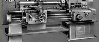
TV-4 (TV4) Training screw-cutting lathe. Purpose, scope
The TV-4 screw-cutting lathe replaced in production the obsolete first school screw-cutting lathes TVSh-2 and TVSh-3 (TV-3) and was produced in the 70s of the last century. The TV-4 machine was replaced by a more advanced model TV-6.
The TV-4 lathe is an educational universal screw-cutting lathe and is intended for all kinds of turning work in workshops of schools for polytechnic training and cold metal cutting.
The educational screw-cutting lathe TV-4, despite its simplified design, has all the components of an “adult” screw-cutting lathe: spindle speed box, guitar, feed box, drive shaft and lead screw, caliper with mechanical feed.
The machine allows you to perform the following types of turning work:
- Grooving and boring of cylindrical and conical surfaces
- End trimming
- segment
- Metric thread cutting
- Drilling and a number of other works
Operating principle and design features of the machine
The front end of the spindle of the TV-4 machine has an M36x4 thread for installing an intermediate flange with a chuck (see the article Lathe chucks). The standard chuck for the TV-4 machine is Ø100 mm.
The spindle of the TV-4 lathe receives 6 stages of rotation (120, 160, 230, 375, 500, 710 rpm) from the gearbox in the headstock.
The gearbox, by switching gears, allows you to reduce the spindle speed required for tapping, as well as for heavy work that requires increased torque. Higher spindle speed is used for finishing work.
The machine is driven by an asynchronous electric motor ~220 V. Through a V-belt transmission and single-stage pulleys, the movement is transmitted to the input shaft of the gearbox. Inside the gearbox, movement is transmitted through gears to the spindle. The spindle, depending on the position of the handles on the headstock, rotates at one of 6 speeds. The direction of spindle rotation is determined by the motor.
From the spindle, the movement is transmitted to the output shaft of the gearbox, then to the guitar, and from it to the input shaft of the gearbox.
The feed box provides 3 caliper feed speeds and can cut 3 metric threads without rearranging gears in the guitar.
At the output of the feed box there is a lead shaft and a lead screw, which rotate alternately at one of 3 speeds.
The lead screw is turned on when threading. The speed of the lead screw is set by the handles on the feed box and determines one of the 3 metric threads (the lead screw can be used in longitudinal feed mode, but is not used so as not to wear it out). The direction of rotation of the lead screw is set by the left handle on the headstock.
The running shaft makes it possible to obtain one of 3 longitudinal feeds of the caliper. The feed speed is set by the handles on the front wall of the feed box.
The lead screw and lead shaft pass through the caliper apron, which converts the rotational movement of the lead screw or lead shaft into forward longitudinal movement of the caliper. Transverse mechanical movement of the support in the TV-4 machine is not provided.
Gearbox lubrication by spraying oil from the oil bath at the bottom of the headstock onto the gears. The feed box is lubricated with a wick from a tray, which is filled with oil once per shift. The apron, caliper, guitar, tailstock and bed are lubricated by hand once per shift.
Main technical characteristics of the school screw-cutting lathe TV-4
Manufacturer - Rostov-on-Don. The main parameters of the machine are in accordance with GOST 18097-93. Screw-cutting and turning machines. Basic dimensions. Accuracy standards.
- The largest diameter of a Disk-type workpiece processed above the bed is Ø 200, mm
- The largest diameter of the Shaft type workpiece processed above the upper part of the support is Ø 125 mm
- Distance between centers - 350 mm
- The longest turning length is 300 mm
- Electric motor power - 0.6 kW
- Full machine weight - 280 kg
Spindle of screw-cutting lathe TV-4
- Threaded spindle end - M36x4
- Spindle hole diameter - Ø 16 mm
- The largest diameter of the processed rod is Ø 15 mm
- Spindle speed limits per minute - (6 steps) 120, 160, 230, 375, 500, 710 rpm
- Standard chuck diameter - Ø 100 mm
Machine care
TV-7, TV-7m machines must be regularly inspected before performing functional duties, and metal shavings must be removed from the parts that determine the direction of movement, installed on the body and support. They are lubricated with oil upon completion of work. The accuracy of manufactured parts and the period of operation of the machines are determined by their care.
All movably connected parts and devices are subject to timely lubrication. The procedure is carried out by a gear immersed in oil, which transfers drops to other elements. The gearbox and feeds are subjected to this procedure.
It is monitored through a peephole located on the headstock. Oil drains from the rear.
Features of installation of the TV-7M machine and its first launch
Installation of the TV-7M educational turning and screw-cutting unit should be carried out on a table or a manufactured stand with a height of no less than 660 mm and no higher than 680 mm from the floor level. The height must be maintained in accordance with the relevant ergonomic requirements.
The cabinet can be made of wood, but to ensure sufficient rigidity of the base, metal corners and sheet metal are best suited. Before fixing the screw-cutting machine, it must be leveled in two planes.
Before using this machine for the first time, you must complete the following mandatory steps:
- carefully read the operating manual of the machine, study its design and safety rules during operation;
- clean non-paintable surfaces of the unit with napkins or rags soaked in solvent to remove the anti-corrosion coating;
- check the presence of grounding; if it is missing, then it must be done in accordance with the rules;
- fill the lubrication and oil filling points;
- check the position of all handles of the lathe control system (they must be in the neutral position);
- connect the power cable to the terminals of the terminal block.
At the initial stage, within 30–40 hours of operation of screw-cutting turning equipment, it is not recommended to perform turning operations at maximum spindle speed.
Safety precautions
Basic operating rules:
- issuing permission to work only if you have special clothing;
- installation of equipment on a rigid foundation;
- grounding device in accordance with the requirements;
- checking the serviceability of moving parts, cutters, and the presence of protective guards;
- using a wooden lattice as a stand;
- properly securing the part to be processed;
- use of cutters with proper sharpening;
- checking the fixation of the tailstock after installing the part in the central part;
- timely removal of metal shavings.
Equipment management
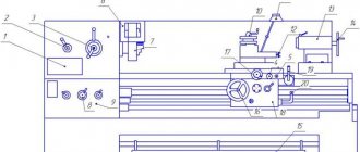
Since TV-7 was created for use as school or educational equipment, managing its operation does not present any great difficulties. Even from the photo of the device it is clear that it is not difficult to master the operation of such a unit.
TV-7 controls (click to enlarge)
The design of the turning TV-7 has several package-type switches; a button responsible for emergency stop of the work process; a button that starts the rack and pinion gear; flywheel to control the longitudinal movement of the carriage; a second flywheel, with which the tailstock is moved; as well as a number of management bodies responsible for carrying out such operations as:
- turning on the reverse mode of operation of the main engine;
- tension of the belt connecting the electric motor to the gearbox;
- starting the feed of the machine support in the longitudinal direction;
- fixing the tailstock on the bed guides;
- moving the slide in the transverse direction;
- change in feed direction;
- activation of the lead screw and the lead roller;
- changing the rotation speed of the spindle assembly;
- selecting the feed rate and pitch of the thread being cut.
The main purpose of TV-7 is to train young specialists
A review of the design of the unit will be incomplete without mentioning the three handles responsible for:
- turning on the lead screw nut;
- quill fastening;
- fixing the cutting head in the required position.
All of these controls allow you to effectively perform simple turning operations on metal workpieces.
Even from a brief overview of the TV-7 model lathe, it is clear that with the help of this device you can quickly master the basics of turning and the principles of managing metalworking technological operations.
Key Features
The TV-7 lathe works with metal workpieces by rotating them. An additional option is cutting on a machine. For this purpose, preheating of the workpiece is not required. Changing the operating mode is carried out by throwing the belt of the driven and drive shafts.
This process is performed when downshifting. This feature provides high functionality and the presence of three additional feeds. The TV-7 lathe is also a screw-cutting machine. With its help, you can get three options for metric threads.