Author: Yuriy Fedorovich Kolesnikov, thermal power engineer
Our time has never been called: the age of the atom, space, plastics, electronics, composites, etc., etc. In fact, our age is still iron - its alloys still form the core of technology; the rest, although very powerful, is periphery. The path of iron into structures, products and structures begins with the smelting of cast iron from ore in a blast furnace.
Note: there are almost no rich iron ores left in the world that are suitable for smelting immediately after extraction. Current blast furnaces operate on enriched sinter and pellets. Further in the text, ore means just such a raw material for ferrous metallurgy.
A modern blast furnace (blast furnace) is a grandiose structure with a height of up to 40 m, a weight of up to 35,000 tons and a working volume of up to 5,500 cubic meters. m, producing up to 6000 tons of cast iron per melt. The blast furnace ensures the operation of a host of systems and units covering an area of tens and hundreds of hectares. This whole facility looks impressive even when stopped with the blast furnace extinguished on a cloudy day, but in operation it is simply enchanting. The release of cast iron from a blast furnace is also an exciting spectacle, although in modern blast furnaces it no longer resembles a picture from Dante’s Inferno.
Giant blast furnace in shutdown and in operation
Release of pig iron from a blast furnace
The basic principle
The operating principle of the blast furnace is the continuity of the metallurgical process for the entire life of the furnace until the next overhaul, which is carried out every 3-12 years; the total service life of a blast furnace can exceed 100 years. A shaft blast furnace: from above, a charge of ore with limestone flux and coke is periodically immersed in portions (in buckets), and molten cast iron is also periodically released from below and the molten slag is drained, i.e. the column of raw materials in the blast furnace shaft gradually settles, turning into cast iron and slag, and is built up on top. However, the path of the ferrous metallurgy to this seemingly simple scheme was long and difficult.
Blast furnace maintenance and repair
Any equipment that operates 24/7 requires constant maintenance. Regulations are included in the technical passport of the equipment. Failure to comply with the maintenance schedule will result in a reduction in service life.
Maintenance work on blast furnaces is divided into periodic and major repairs. Periodic work is carried out without stopping the work process.
Major repairs are divided into three categories based on the volume of work performed. During the first discharge, all equipment is inspected, and melts are removed from the shaft. During the second discharge, the lining is repaired and failed equipment elements are replaced. With the third category, the unit is completely replaced. Typically, such repairs are combined with modernization or reconstruction of the blast furnace.
Story
The Iron Age gave way to the Bronze Age mainly due to the availability of raw materials. Raw iron was much inferior to bronze in everything else, including labor intensity and cost; the latter, however, during the time of slavery, few people worried. But bog ore, which is almost pure iron hydroxide, or high-grade iron ore, could be found everywhere in ancient times, in contrast to the deposits of copper and - especially - tin needed to obtain bronze.
The first iron from mineral raw materials was obtained, judging by archaeological data, by accident when the wrong ore was loaded into a copper smelter. When excavating ancient smelters, apparently discarded pieces of iron smelting are sometimes found near the furnaces (see below). The shortage of raw materials forced us to take a closer look at them, but the ancients, in general, thought no worse than us.
Initially, iron was obtained from ore so-called. using the cheese-blowing method in a blast furnace (not a blast furnace!). The reduction of Fe from oxides occurred due to the carbon of the fuel (charcoal). The temperature in the blast furnace did not reach the melting point of iron at 1535 degrees Celsius, and as a result of the reduction process, a mass of sponge iron supersaturated with carbon - kritsa - was established in the blast furnace. To extract the kritsa, the domnitsa had to be broken, and then the kritsa had to be compacted and the excess carbon literally knocked out of it, forging long, hard and persistently with a heavy hammer. From the point of view of that time, the advantages of the cheese-making process were the ability to produce kritsa in a very small furnace and the high quality of kritsa iron: it is stronger than cast iron and is less susceptible to rusting. How to obtain iron using the cheese-making method, see the video below.
Video: smelting iron using the cheese-blowing method
China was the first, much earlier than other countries, to move from slavery to feudalism. Slave labor ceased to be used in production there and commodity-money relations began to develop even when Ancient Rome was firmly in the West. The cheese-making process immediately became unprofitable, but it was no longer possible to return to bronze, there simply wouldn’t be enough of it. The role of flux in facilitating the smelting of metal from ore was known back in the Bronze Age; to smelt iron it was only necessary to increase the pressure, and the Chinese, through trial and error, by the 4th century. n. e. learned to build blast furnaces with supercharged bellows driven by a water wheel, on the left in Fig.
Antique blast furnaces
To an identical design in the second half of the 15th century. The Germans arrived, on the right in the figure. Quite independently: historians trace a continuous series of improvements from the blast furnace through the stukofen and blauofen to the blast furnace. The main thing that German metallurgists contributed to ferrous metallurgy was the combustion of high-quality coal into coke, which greatly reduced the cost of fuel for a blast furnace.
The terrible enemy of the original blast furnace process was the so-called. frosting, when, due to a violation of the blast regime or a lack of carbon in the charge, a “goat sat down” in the furnace, i.e. the charge was sintered into a solid mass. To remove the goat, the blast furnace had to be broken. This historical example is illustrative.
The Ural factory workers, the Demidovs, are known to be famous for their cruelty and inhumane treatment of workers, especially since there were many of them “unpatched,” runaway serfs and deserters. The “workers” were once completely fed up, and they presented their demands to the clerk, which, it must be said, were quite modest. According to Demidov’s custom, he literally sent them in Russian. Then the workers threatened: “Come on, come here yourself, otherwise we’ll put the goat in the oven!” The clerk stretched out, turned pale, mounted his horse and galloped away. Less than an hour passed (in the days of horse-drawn transport - instantly), the lathered “himself” galloped up on a lathered horse, and immediately said: “Brothers, what are you doing? What do you want me to do?” The workers repeated their demands. The owner, figuratively speaking, sat down and said “Koo!” and immediately ordered the clerk to do everything thoroughly.
Until the 19th century The blast furnaces were actually raw materials: unheated and not oxygen-enriched atmospheric air was blown into them. In 1829, the Englishman J.B. Neilson tried to heat the blown air to just 150 degrees (having previously patented his air heater in 1828). The consumption of expensive coke immediately dropped by 36%. In 1857, also an Englishman, E. A. Cowper, invented regenerative air heaters, later named Cowpers in his honor. In the cowpers, the air was heated to 1100-1200 degrees due to the afterburning of exhaust blast furnace gases. Coke consumption decreased by another 1.3-1.4 times and, what is also very important, the blast furnace with cowpers turned out to be not susceptible to fouling: when signs of fouling appeared, which happened extremely rarely with very serious violations of the technical process, there was always time to inflate the furnace. In addition, in cowpers, due to the partial disintegration of water vapor, the intake air was enriched with oxygen to 23-24% versus 21% in the atmosphere. With the introduction of the Cowper blast furnace, the processes in the blast furnace from the point of view of thermochemistry reached perfection.
Blast furnace gas immediately became a valuable secondary raw material; They didn’t think about ecology back then. In order not to waste it, the blast furnace was soon supplemented with a blast furnace apparatus (see below), which made it possible to load charge and coke without releasing blast furnace gas into the atmosphere. This is where the evolution of the blast furnace basically ended; its further development followed the path of important, but partial improvements, improvement of technical and economic, and then environmental indicators.
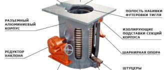
Installation features
Such a stove can be lined with brick, but if it is located in a separate or utility room, then this is not necessary.
- The parts of the chimney must be connected in the direction opposite to the movement of smoke.
- No flammable objects should be placed near the stove; there should be free space around it.
- The chimney must be made collapsible so that it can be cleaned periodically.
- You can attach a pipeline to the barrel in the form of a loop through which the liquid will pass into the heating system. This way it will be possible to heat not just one room, but the whole house.
- To be able to regulate the heating intensity, a tap is installed in the system near the boiler, with which it will be possible to limit the flow of hot liquid.
A homemade long-burning stove is an excellent solution for heating a summer house, garage or greenhouse when there is no centralized or gas heating and no money to buy expensive equipment.
Domain process
The general diagram of a blast furnace with service systems is shown in Fig. The foundry yard is an accessory to small blast furnaces that produce mainly foundry pig iron. Large blast furnaces produce over 80% of converting pig iron, which the iron truck immediately takes from the casting site to the converter, open-hearth or electric smelting shops for conversion into steel. Foundry cast iron is cast into earthen molds, usually into ingots - ingots - which are sent to manufacturers of metal products, where they are melted down for casting into products and parts in cupola furnaces. Cast iron and slag are traditionally discharged through separate openings - tapholes, but new blast furnaces are increasingly equipped with a common taphole, divided into cast iron and slag by a heat-resistant plate.
General diagram of a blast furnace
Note: blanks of raw iron without excess carbon, obtained from cast iron and intended for processing into high-quality structural or special steel (second to fourth stages) are called slabs. In metallurgy, professional terminology is developed in no less detail and precision than in maritime affairs.
At present, it seems that there are no reserves of coal and coke ovens left at blast furnaces. A modern blast furnace runs on imported coke. Coke oven gas is a deadly poisonous environmental killer, but it is also a valuable chemical raw material that must be used immediately, while still hot. Therefore, coke production has long been separated into a separate industry, and coke is supplied to metallurgists by transport. Which, by the way, guarantees the stability of its quality.
How does a blast furnace work?
An indispensable condition for the successful operation of a blast furnace is an excess of carbon in it during the entire blast furnace process. For the thermochemical (highlighted in red) and technical and economic diagram of the blast furnace process, see Fig. Iron smelting in a blast furnace takes place as follows. way. A new blast furnace or one reconstructed after a 3rd category overhaul (see below) is filled with materials and ignited with gas; also heat one of the cowpers (see below). Then they start blowing air. The combustion of coke immediately intensifies, increasing the temperature in the blast furnace, and the decomposition of the flux begins with the release of carbon dioxide. Its excess in the furnace atmosphere with sufficient blown air does not allow the coke to burn out completely, and carbon monoxide - carbon monoxide - is formed in large quantities. In this case, it is not a poison, but an energetic reducing agent, greedily taking oxygen away from the iron oxides that make up the ore. The reduction of iron with gaseous monoxide, instead of less active solid free carbon, is the fundamental difference between a blast furnace and a blast furnace.
Chemical processes and temperature in different zones of a blast furnace
As the coke burns and the flux breaks down, the column of materials in the blast furnace settles. In general, a blast furnace consists of two truncated cones formed by the bases, see below. The upper, high one is the blast furnace shaft, in which iron from various oxides and hydroxides is reduced to iron monoxide FeO. The widest part of the blast furnace (the place where the bases of the cones meet) is called raspar (raspar, raspar - incorrectly). In steam, the settling of the charge slows down, and iron is reduced from FeO to pure Fe, which is released in drops and flows into the blast furnace. The ore seems to be steaming, sweating molten iron, hence the name.
Note: the time it takes for the next batch of charge in a blast furnace to travel from the top of the shaft to the melt in the forge ranges from 3 to 20 or more days, depending on the size of the blast furnace.
The temperature in a blast furnace within the loading column increases from 200-250 degrees under the throat to 1850-2000 degrees in steam. Reduced iron, flowing down, comes into contact with free carbon and at such temperatures becomes highly saturated with it. The carbon content in cast iron exceeds 1.7%, but it is impossible to knock it out of cast iron. Therefore, the cast iron obtained from the blast furnace is immediately taken away liquid for the first processing into ordinary structural steel or slabs, so as not to waste money and resources on its remelting, and the blast furnace, as a rule (large and extra-large blast furnaces - exclusively), operates as part of a metallurgical plant .
Foundation and chimney
Since the metal part of the structure will become very hot during operation, the stove must be installed on a foundation. Its weight is light, and it is not necessary to make a recess for the foundation; a simple slab is made, which can consist of a layer of brick covered with mortar.
To remove combustion products, it is necessary to make a chimney. You can take a pipe with a diameter of 15 cm or more. For it to work effectively, the straight part must be larger than the diameter of the barrel. It is better not to bend the chimney, and if this is necessary, then the bending angle should be more than 45 degrees.
Related article: Choice of thrifty housewives: Veles curtains from a Belarusian manufacturer
As for the reflector, it can be installed or not installed. If there is a reflector, such a stove will work even more efficiently, since it allows you to redistribute heat flows.
Blast furnace design
The design of a blast furnace as a structure is shown in Fig:
Blast furnace design
The entire blast furnace is assembled in a steel case with a wall thickness of 40 mm. The bottom (under) of the cylindrical furnace is walled up in the heat-resistant stump of the blast furnace (base, head, top of the underground foundation). The lining of the hearth reaches a thickness of 1.3-1.8 m and is heterogeneous: the axial zone of the flange is lined with high-alumina brick, which conducts heat poorly, and the sides are lined with graphite materials, which have a fairly high thermal conductivity. This is necessary, since the thermochemistry of the melt in the furnace has not yet “calmed down” and some excess heat is released there against losses due to cooling. If it is not moved to the side, onto a heat-resistant stump, the structure of the blast furnace will require another repair of a higher level (see below).
The part of the blast furnace that expands upward - the shoulders - is lined with already graphitized blocks with a thickness of approx. 800 mm; The fireclay lining of the shaft is of the same thickness. Fireclay, like the lining of a hearth with shoulders, is not wetted by molten slag, but is closer to the latter in chemical composition. That is, during operation, the blast furnace is minimally overgrown with soot and holds the internal profile better, which simplifies and reduces the cost of regular repairs.
The furnace and shoulders work in the most difficult conditions, excess weight loads are dangerous for them, so the blast furnace shaft rests with its shoulders (ring-shaped extension) on a strong steel ring - the marator - resting on steel columns, walled up in a stump. Thus, the weight loads of the hearth with shoulders and the shaft are transferred to the base of the blast furnace separately. Hot air from the cowpers is blown into the blast furnace from a ring-shaped tubular collector with thermal insulation through special devices - tuyeres, see below. There are from 4 to 36 tuyeres in a blast furnace (in giant blast furnaces for 8,000-10,000 tons of charge and 5-6 thousand tons of cast iron per day).
Repair ranks
The current state of the blast furnace is determined by the chemical composition of the cast iron and slag. If the content of impurities reaches the limit, repair of a 1st category blast furnace is prescribed. Melts are released from the forge, the cowpers are jammed (see below) and the blast furnace is left at low pressure, with a temperature inside the forge of 600-800 degrees. Level 1 repairs include visual inspection, mechanical inspection, furnace profile measurements, and lining sampling for chemical analysis. Once upon a time, a blast furnace was inspected at low breaths by people in special protective suits with self-contained breathing devices; now this is done remotely. After repairing the 1st category, the blast furnace can be restarted without ignition.
The result of the 1st category repair most often (unless bad ore, flux and/or defective coke was missed) is a 2nd category repair, during which the lining is corrected. Its partial or complete re-laying, straightening or replacement of the top apparatus is carried out in the order of repair of the 3rd category. As a rule, it is timed to coincide with the technical reconstruction of the enterprise, because requires a complete stop, cooling the oven, and then rebooting it, igniting it and restarting it.
Furnace lining
The refractory lining (masonry) of a blast furnace is designed to reduce heat losses and protect the casing from exposure to high temperatures and from contact with liquid metal and slag.
Refractories used . For the lining of a blast furnace, high-quality fireclay bricks, high-alumina bricks, carbon blocks, and sometimes silicon carbide bricks are used. The basis of fireclay is SiO2 and Al2O3.
For blast furnaces, the standard provides for three types of fireclay products with an Al2O3 content of at least 42, 41 and 39%, respectively; they are characterized by increased density and strength, high fire resistance (> 1750 ° C), low Fe2O3 content (
Bricks with a higher Al2O3 content are used for laying the bottom of the furnace, and with a lower content - for laying the top. In addition, for laying furnaces with a volume of ≤1033 m3, the standard provides for a grade of fireclay with a lower (> 37%) Al2O3 content, lower fire resistance (> 1730°C), strength and density. The brick can be 230 mm (normal) and 345 mm (one and a half) long. The use of bricks of different lengths ensures good interlacing of masonry seams.
High-alumina mullite brick used for laying the flange contains > 63% Al2O3 with fire resistance > 1800 °C. Blast-furnace silicon carbide brick contains > 72% SiC and > 7% nitrogen and differs from refractories based on Al2O3 and SiO2 in significantly greater strength and thermal conductivity.
Carbon blocks are made from coke and burnt anthracite with the addition of a small amount of coal tar pitch as a binder. The length of the blocks reaches 3...4 m, they are rectangular in section 400×400 and 550×550 mm. Blocks in combination with large-sized high-alumina bricks (400×200×100 mm) are used for laying the lowest part of the furnace - the flange.
The seams between refractory bricks are filled with mortar made from mortars corresponding to the class of brick. Mortar is a powder consisting of crushed fireclay and refractory clay. For critical types of masonry, mortars are used with the addition of small amounts of surfactants and adhesives (soda, sulfite-alcohol stillage), which makes it possible to prepare solutions with lower humidity while simultaneously increasing their plasticity.
To fill the seams between carbon blocks, a carbon paste consisting of coke and resin is used. The gap between the blocks is allowed no more than 0.5 mm for vertical and no more than 1.5 mm for horizontal seams.
Leschad . Previously, the flanks of blast furnaces were laid out of high-quality fireclay bricks. However, the increase in the volume of furnaces and the intensification of smelting caused the rapid destruction of such masonry. Therefore, at present, flakes are made either all-carbon or combined from carbon and high-alumina refractories. The use of carbon refractories is due to the fact that, due to their high thermal conductivity, overheating is reduced and, as a result, the destruction of the masonry of the flange is reduced.
Horn . The lining of the hearth up to the level of the tuyeres is made of carbon blocks, and in the areas of the tuyeres and cast iron and slag tapholes from fireclay (> 42% Al2O3) bricks, since carbon here can be oxidized by blast oxygen, carbon dioxide (CO2), as well as water vapor from the refractory masses . When working on anhydrous tapping masses, the cast iron taphole area is made of carbon blocks. To prevent oxidation of carbon blocks during the furnace blowing period, they are protected by masonry in one row of fireclay bricks.
The thickness of the lining at the bottom of the hearth reaches 1600 mm. From the outside, the furnace masonry is cooled with smooth stove-top refrigerators.
Shoulders . The masonry of the shoulders is most often made of thin-walled (thickness 230 or 345 mm) from fireclay (> 42% Al2O3) bricks in one row, with the brick adjacent to the peripheral slab refrigerators with poured brick. Sometimes silicon carbide bricks are used instead of fireclay. The masonry of the shoulders quickly wears out and instead of it, a layer of scavenge (frozen slag and small pieces of charge) is formed on the surface of the refrigerators.
Mine and steam . The masonry of the steam chamber and the cooled part of the shaft (~2/3 of its height from below) is made of fireclay (> 41...42% Al2O3) or silicon carbide brick, and the masonry of the upper uncooled part of the shaft is made of fireclay containing > 39% Al2O3. The bricks are laid in two to three rows in a bandage.
The masonry of the shaft with steam can be thick-, medium- and thin-walled. In previous years, thick-walled masonry was widely used (the thickness of the top of the shaft is 800...900 mm and up to 1300 mm in the area of \u200b\u200bthe rasp) with horizontal refrigerators buried in the masonry and serving as its support. However, due to the fact that the refrigerators are located at a distance from each other, the casing is poorly cooled, and after wear of the lining, local overheating occurs, causing thermal deformation and the possibility of cracks.
In addition, cutouts in the casing for installing horizontal refrigerators reduce its strength and make the casing less airtight. In connection with this, thin- and medium-walled shafts have been made in recent years. The thin-walled shaft (and steam) has a masonry thickness of 230...345 mm in the cooled part and 575...690 mm in the upper uncooled part with cooling by vertical finned refrigerators, and some of the refrigerators have horizontal protrusions that serve as support for the masonry and help hold the scull.
The middle-wall shaft has a masonry thickness of 575...900 mm in the cooled part and 700 mm in the uncooled part; cooling is either combined from vertical finned refrigerators in combination with horizontal ones, or from vertical finned refrigerators having horizontal projections.
In the steam and cooled part of the shaft, as the brick wears out, a layer of skull is formed. In order to reduce the pressure from the masonry expanding during heating on the furnace casing and to prevent its rupture, a gap of 70...200 mm is provided between the lining and vertical refrigerators along the entire height of the furnace (except for steam), filled with chamoto-asbestos or plastic carbon mass.
Koloshnik . The fire pit lining itself consists of one row of fireclay bricks laid out near the casing. Behind it there is a “beam protection”, which absorbs the impacts of pieces of charge falling from above during the loading process. Its widespread variety consists of steel segments - cast hollow boxes filled with fireclay bricks. The segments are arranged in several annular rows along the height of the top; adjacent segments around the circumference are connected to each other by bolts.
The entire flue protection is attached to the casing using several hangers, in each of which the segments are attached to a vertical plate connected to an earring, which is freely suspended on a pin inserted into the hole of the bracket; the latter is bolted to the casing. This suspension allows all segments to move upward if the shaft masonry grows in the vertical direction as a result of its heating.
Systems and equipment
The design of a modern blast furnace includes dozens of auxiliary systems controlled by powerful computers. Today's steelworkers still wear hard hats and sunglasses, but they sit in air-conditioned cubicles at consoles with displays. However, the operating principles of the basic systems and devices that ensure the operation of a blast furnace remain the same.
Cowpers
The Cowper air heater (see figure) is a cyclic device. First, the regenerator nozzle, made of heat-intensive, heat-resistant material, is heated by the burning blast furnace gases. When the nozzle temperature reaches approx. 1200 degrees, the cowper switches to blast: the outside air is driven through it into the blast furnace in a countercurrent manner. The nozzle has cooled down to 800-900 degrees - the cowper is switched again but warmed up.
Appearance and structure of blast furnace cowpers
Since the blast furnace must be blown continuously, there must be at least 2 cowpers, but at least 3 of them are built, with a reserve for accidents and repairs. For large, extra-large and giant blast furnaces, cowper batteries of 4-6 sections are built.
Top apparatus
Design of the blast furnace top apparatus
This is the most critical part of the blast furnace, especially in light of current environmental requirements. The structure of the blast furnace blast furnace is shown in Fig. on right; it consists of 3 coordinated gas valves. Its work cycle is as follows:
- initial state – the upper cone is raised, blocking the exit into the atmosphere. The windows at the bottom of the rotating funnel are located on a horizontal partition and are blocked. The lower cone is lowered, allowing blast furnace gases to escape to the smoke exhauster and then into the cyclone;
- the skip (see below) tips over and dumps the flue of materials into the receiving funnel;
- a rotating funnel with windows in the bottom turns and passes the load onto a small cone;
- the rotating funnel returns to its original state (the windows are closed with a partition);
- a large cone rises, cutting off blast furnace gases;
- the small cone lowers, allowing the load to pass into the intercone space;
- a small cone rises, further blocking the exit to the atmosphere;
- the large cone lowers to its original state, releasing the charge into the blast furnace shaft.
Thus, the materials in the furnace shaft are laid out in layers, convex at the bottom and concave at the top. This is absolutely necessary for the normal operation of the blast furnace, so the lower (large) valve is always reverse-conical. The upper ones may be of a different design.
Skip
Skip, from English. - ladle, scoop, gaping mouth. Kolosha (from French) – a handful, a ladle, a ladle. By the way, this is where galoshes come from. Blast furnaces are supplied primarily with skip material lifts. The blast furnace skip (on the right in the figure) scoops up a bucket of material from the skip pit, is lifted by a special mechanism along an inclined trestle (on the left in the figure), overturns into the blast furnace apparatus and returns back.
Skip material hoist and blast furnace skip
Tuyeres and tapholes
The structure of a blast furnace tuyere is shown on the left in the figure, the cast iron taphole is in the center, and the slag taphole is on the right:
Construction of a tuyere and tap hole for a blast furnace
The tuyere nozzle is aimed at the very heart of the blast furnace process; through it it is convenient to visually control its progress, for which purpose a peephole with heat-resistant glass is installed on the air duct of the tuyere. The air pressure at the tuyere nozzle exit is 2-2.5 ati (2.1-2.625 MPa above atmospheric pressure). After releasing the melt, the tapholes are sealed with a lump of heat-resistant clay. Previously, they were shot at with a plastic clay ball from a special cannon for this purpose. Nowadays, the tapholes are sealed with a remotely controlled electric gun (the name is a tribute to tradition), which approaches the taphole closely. This greatly reduced the accident rate, injury risk and environmental friendliness of the blast furnace process.