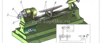
Let's look in detail at the principle of operation of a metal screw-cutting lathe, what types of machines there are and what they are for, what is needed in general, what useful things can be done with them.
Let's not forget about the description of the main components of the lathe, what it consists of, its structure, we will give, as an example, electrical and kinetic diagrams of the machines.
Design and operating principle
Most lathes are similar in design and have the same features. They differ only in size and location of some parts.
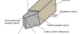
On lathes, parts are processed using a cutting tool as a result of rotation. With the forward movement of the cutter, a layer of metal is removed from the surface of the workpiece, and it is given the desired appearance and shape. Modern machines are highly accurate; threads can be cut to any profile.
The operating principle of a lathe is as follows:
- the tool for work is inserted into the tailstock quill;
- the tailstock must be installed in accordance with the dimensions of the part; it moves along the guides of the frame;
- a caliper is located between the front and tailstocks; during operation, it moves along the guides using a carriage;
- Tool holders are selected depending on the size of the part; they can be either single or intended for several cutters.
This is interesting: Metal cutters for drills: types, design, selection rules
Some maintenance tips
Knowing how to maintain the machine, you can extend its service life. Adviсe:
- After processing the workpieces, it is necessary to clean the equipment from residual material.
- Work only with solid and sharp incisors.
- Check the functionality of individual elements of the machine before starting it.
- Use coolant during long-term operation.
We must not forget about the use of safety glasses, which will help protect your eyes from metal shavings.
Lathes are used to carry out various technological operations. Knowing the structure of this equipment, you can repair breakdowns, properly care for the mechanisms, and clean them.
Types of lathes
The classification is quite complicated, since it is made according to several parameters (type of work, degree of automation, weight, etc.). Therefore, only a general overview of the most famous varieties.
- Semi- and automatic machines.
- Single or multi-spindle.
- Revolving.
- Screw-cutting.
Multi-incisor
Carousel
Backing
Marking of lathes
It is alphanumeric. The explanation of positions (from left to right) in the product designation is as follows.
- 1st (digit). For lathes – always “1”.
- 2nd (number or letter). Type of equipment. For example, for a rotary machine it is “5”, a frontal machine – “6”, a screw cutter – “I”.
- 3rd (number). Main parameter (in dm). This is usually taken to be the height of the centers.
- 4th (letter). It is not always indicated. Indicates features of a lathe. For example, the letter “T” indicates that it is modified; “P” – increased accuracy, and so on.
Main characteristics
Each lathe has its own capabilities. What should you pay attention to first?
- The maximum cross-section of a metal workpiece that can be clamped in the spindle.
- The distance between the centers of the headstocks in their extreme position. The maximum length of the sample that can be processed depends on this.
- Limit thickness of a metal part. It is determined by the distance from the spindle - tailstock axis to the caliper.
There are quite a few modifications of lathes, but if you look into their design, there are no fundamental differences. The main difference is in the layout of the machines, the location of some components and their design (shape, dimensions, etc.). For each product, the manufacturer must include a set of documentation, according to which, having a general understanding of the structure of a lathe, it will not be difficult to understand the nuances.
How to choose the right one
When choosing a suitable tool, you need to “try on” the necessary queries against the listed parameters. The following recommendations will help you make the right decision:
- The home version usually weighs no more than fifty kilograms, and the power of the unit varies from 0.15 to 3 kW.
- It is better to decide in advance on the scope of work to be performed so as not to overpay for unnecessary functions and capabilities.
- Make sure that the machine elements are polished.
- Calculate the frequency of use (for frequent work it is better to choose semi-professional models).
- Pay attention to the manufacturer (Swiss is considered the best).
- Choose a device with a CNC system.
Varieties and design features
There are actually a lot of machines and they perform all kinds of metal processing operations, but we will highlight the most famous types
Multi-incisor
Designed for processing complex parts made from pipes, shaped profiles or rods of different sections. Multi-cutter or multi-spindle machines are mainly used in batch production.
Performed operations:
- drilling;
- thread;
- turning;
- pruning;
- boring;
- countersinking;
- deployment.
Multi-cutting machines have high productivity due to the large area of the drive mechanism, rigidity of the structure, and the ability to perform several operations simultaneously.
Carousel
A group of machines for working with large-sized parts and workpieces. The parts processed on them are short in length, but have significant weight and diameter.
Features of carousel models:
- used for processing conical or cylindrical surfaces;
- grooves of various configurations are made;
- You can also do grinding, milling, trimming ends;
- thread cutting.
In addition to the basic elements of any lathe, this type has additional equipment:
- table with faceplate;
- racks for moving the traverse.
Backing
The machines are designed for processing the back surfaces of tool teeth. It can also be used to perform other turning operations. The backing machine is distinguished by its special support design. The part is backed up as follows:
- rotational movement of the part;
- reciprocating movement of the cutting tool towards the part.
Screw-cutting
The most common group of machines. Widely used in serial and individual production. Screw-cutting models can be found in workshops, schools, and in any industry. They are easy to operate and maintain.
REFERENCE! The screw-cutting lathe is a universal model for all kinds of processing of metal workpieces. It can be used to make various types of threads: modular, inch, metric.
Structural elements:
- bed;
- front and rear stock;
- caliper;
- apron;
- gearbox.
Revolver
Revolver group machines are designed for processing parts from calibrated rods. Operations that can be performed on this equipment:
- turning;
- boring;
- shaped turning;
- countersinking;
- drilling;
- thread formation;
- deployment.
REFERENCE! The name of the machines in this group comes from a special holder. It can be driven or static. The drive type gives more possibilities for carrying out various operations.
Universal
Universal lathes include screw-cutting machines, since they can perform almost any metal operation.
Main technical characteristics of the universal machine:
- rotation speed (number of revolutions); accuracy class; it is indicated in the product labeling with the letters S, B, N, A, P;
- number of gears;
- what sizes of parts can be installed;
- weight and dimensions of the machine;
- the amount of feed and maximum movement along the axis.
Options and explanation of modification options
The marking of equipment shows what features it has and its scope of application.
Lathes have a letter and a number name. Letter designations characterize its design features: level of automation, degree of processing accuracy, modification, type of CNC.
Meaning of letters in device markings:
- C – special accuracy.
- B – high accuracy.
- N – normal accuracy.
- A – particularly high accuracy.
- P – increased accuracy.
The numbers indicate:
- the first digit 1 indicates that it is a lathe;
- the second digit indicates the device type;
- the third and fourth show the processing features.
For example, 16K20T means:
- 1 – lathe;
- 6 – frontal type;
- 20 – 200 mm main parameter;
- T – modified.
Safety precautions
Before starting work you need:
- Make sure that the workpiece is installed correctly and that the cutter is securely fixed;
- Check that all tools and foreign objects have been removed;
- Wear safety glasses and lower the protective glass.
During operation:
- Do not touch rotating parts;
- Take off your glasses and remove the protective glass;
- Stop the spindle by hand.
After completing the work, it is necessary to turn off the power to the machine and additional equipment.
This is interesting: Ballerina on tiles: types and use of drills for large holes
Rules for executing schemes
The execution of graphic images of kinematic diagrams is carried out using the following rules:
- choosing the correct designation for the design used;
- precise indication of the location of a separate part;
- the sequence of their interaction;
- line width (set by existing standards);
- correct display of footnotes;
- applying the necessary inscriptions and symbols.
The rules for executing kinematic diagrams consist in describing the following structural units:
- individual elements;
- lines of kinematic connections;
- links;
- kinematic pairs (combine two or more elements).
The developer has the right to choose the scale at his own discretion. This is permitted by approved standards. The drawing may not comply with the actual arrangement of structural components in the unit body.
A block (device, unit) is considered a separate component of the circuit. It is designed to perform certain functions. Its peculiarity is that it cannot be divided into smaller parts without losing its functionality. Such elements are: a set of gears, one or more shafts, installed bearings, and an electric motor used.
The connection line between parts is indicated by a segment of a given length and thickness. It indicates the presence of a communication mechanism between individual products or devices. If this connection is made rigidly enough, the structure is combined into a link. The combined parts and links into a single whole is called an installation.
For a more detailed description of the interacting elements or links, transmission of the direction of movement, it is possible to combine them into so-called kinematic pairs. The features and order of execution of graphic images depend on their purpose.
Functional diagrams display individual design parts that are involved in the main process of motion transmission. For convenience (if possible), several parts are combined into separate functional groups. The drawing must show their functional connections. Each of them has its own graphic symbol. It is established by existing standards and rules for the design of drawings. For a better understanding of the ongoing technological process, it is recommended to plot the technical characteristics of the components used. In addition to explanatory notes, it is allowed to place a sheet of tables or diagrams on a free space.
Schematic diagrams show parts or their groups. These could be shafts, transmission mechanisms or a finished engine. They give an idea and understanding of the operating principles of the entire unit used. Each part or node is depicted in a disabled state (without indicating the order of interaction with other parts). They are compiled to carry out adjustments and debugging of the assembled unit. For this purpose, all basic kinematic connections are depicted: mechanical and non-mechanical. These connections are drawn between individual elements, kinematic pairs or groups of elements. Graphically, they are located within the boundaries of the contour indicating the body of the unit. The drawing of each mechanism, consisting of several components, can be executed in a separate document. A corresponding link is made on the main sheet. If several identical parts are used as part of a separate unit or a whole device, one drawing is allowed. The rest are depicted with acceptable simplifications. The position of the components can be selected based on the most optimal interaction process. If this is not enough, you can depict the final position of the part with dotted lines.
For better understanding, it is allowed to transfer elements over the surface of the sheet. A prerequisite is the preservation of kinematic and functional connections. If there is not enough space on the drawing field within the boundaries of the unit body, it is allowed to move a separate part outside the boundaries. In this case, explanations for references must be provided. They must ensure the preservation of kinematic connections.
The circuit diagram must indicate:
- the maximum permissible number of revolutions of rotating shafts and transmission links;
- permissible deviation of the part from the original state;
- reference tables;
- graphs and diagrams;
- characteristics obtained by calculation at the design stage;
- inscriptions to explain the specifics of individual products or kinematic pairs.
The diagram, developed to explain the ongoing dynamic processes, includes the dimensions of each product indicating the permissible values of mechanical loads. The characteristics of the shafts, location, and supports used are detailed on it. When crossing various parts, it is necessary to maintain the continuity of the drawn lines. When superimposing images of various structures, the distant one is depicted as invisible. All lines and figures are executed according to the rules of drawing graphics.
The kinematic diagrams show:
- solid lines of the established thickness indicate rotating parts;
- lines thinner by half indicate structures that are indicated with simplifications, for example, worm gears or gears;
- the relationships between individual components, especially kinematic pairs, are drawn with dotted lines;
- indication of the relationship between the engine and transmission mechanisms - double dotted lines;
- all connections obtained by calculation at the design stage are drawn with triple dotted lines during finalization.
Kinematic groups are given names. It explains the type and functionality. Features of the feed drive or the specifics of the worm gear may be indicated. All these explanations are made as written inscriptions on a specially depicted shelf. All these inscriptions can be combined into a separate list. It contains special notes indicating the characteristics known from reference books and standards, obtained by calculation, and the characteristics obtained in the process of debugging and adjusting the entire mechanism. In this case, such parameters are marked with a special inscription, which indicates that they are selected during regulation.
Regulatory documents
The procedure and rules for designating all the parts that make up the mechanism on all types of diagrams are established by accepted state standards. These rules regulate the order of design of graphic elements (figures, inscriptions, symbols) on kinematic diagrams. They are mandatory for drawing drawings for any mechanisms and assemblies.
This list includes:
- standard defining the list of main types of explanatory inscriptions - GOST 104-68;
- GOST 2.701-84, includes an explanation of the main types and types of schemes being developed;
- list of established symbols permitted for use by GOST 2.721–74;
- list of symbols: conventional graphic and general purpose GOST 2.747–68;
Download GOST 104-68
Download GOST 2.747-68
Download GOST 2.701-84
Download GOST 2.721-74
They determine the location and rules of the graphic image (choice of line thickness, icon shape, image of footnotes).
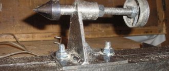
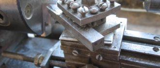
Caliper structure
A lathe support is a unit that ensures the fixation of the cutting tool, as well as its movement in the inclined, longitudinal and transverse directions. It is on the support that the tool holder is located, moving with it due to a manual or mechanical drive.
Support with carriage for machine Optimum D140x250
The movement of this unit is ensured by its structure, which is characteristic of all lathes.
- The longitudinal movement, for which the lead screw is responsible, is performed by the caliper carriage, while it moves along the longitudinal guides of the frame.
- Transverse movement is performed by the upper - rotating - part of the support, on which the tool holder is installed (such movement, due to which the depth of processing can be adjusted, is carried out along the transverse guides of the support itself, which are shaped like a dovetail).
Quick-change tool holder MULTIFIX cartridge type
The tool holder, also called the cutting head, is installed on the top of the support. The latter can be fixed at different angles using special nuts. Depending on the need, single or multiple tool holders can be installed on lathes. The body of a typical cutting head has a cylindrical shape, and the tool is inserted into a special side slot in it and secured with bolts. There is a protrusion on the bottom of the cutting head that fits into a corresponding slot on the support. This is the most typical tool holder mounting scheme, used primarily on machines designed to perform simple turning work.
Let's talk about engines
Commutator motor
Commutator and asynchronous motors are installed on the end devices. What is the difference? The commutator motor has a high torque, but is inferior to an asynchronous motor in ease of maintenance (replacing brushes). The second motor has a long service life and lower noise levels.
The engine drives the cutting element. The torque of the disk is provided by two types of transmission - through belts or teeth. Each type of transmission has a number of advantages and disadvantages: for example, a gear transmission eliminates the possibility of slipping (idling) during extreme loads. The belt type of torque transmission puts less load on the engine and contributes to its longevity. However, belts often break at the wrong moment, stopping work.
Asynchronous motor
The cross-cutting machine has a large cutting width, which is further limited when working at an angle. The cutting angle is increased by installing the bar along the cutting line.
History of the device
The history of a lathe with a caliper begins in 1712, when Andrey Konstantinovich Nartov, a mechanic from Russia, was the first to invent this mechanism. This significantly simplified the work with the device, because the turner no longer needed to hold the cutting tools with his own hands while processing the desired element.
This invention gave a powerful impetus, followed by the rapid development of metal and wood lathes.
Although the creation of the turning device and caliper is attributed to the Englishman Maudsley, the Russian mechanic was still more than seventy years ahead of him.
Functional range
Let's move on to consider functions and types. The cross-cutting machine can be professional or amateur. Note that the set of functions of professional and amateur models differs slightly. The difference between the models lies in the quality of the materials from which the device is made and the strength level of the individual elements. In our case, this is a motor, a saw blade and a gearbox.
Cross-cutting machine diagram
The central problem with cross-cutting machines is the engine. Manufacturers often skimp on quality materials and install powerful engines without an additional cooling system. Intensive use of the machine leads to rapid engine breakdown. The described problem occurs mainly in amateur models.
A professional tool is distinguished not only by the quality of processing of the metal product, but also by its long service life, which is why it is used mainly in industry. An expensive cross-cutting machine can work more than 8 hours a day without breaks.