Feed mechanism
The feed mechanism tells the caliper the required direction of movement.
The direction is set with a bit. The bit itself is located in the headstock housing. It is controlled via external handles. In addition to the direction, you can also change the amplitude of movement of the caliper using interchangeable gears of different numbers of teeth or a feed box. In the scheme of machines with automatic feed, there is a lead screw and a roller. When carrying out high-precision work, a lead screw is used. In other cases, a roller is used, which allows you to keep the screw in ideal condition longer for performing complex elements.
DIY CNC machine assembly
Rating: 3/5
Many people believe that assembling a CNC machine with their own hands is quite problematic. But that's not true. Having the necessary knowledge, the device can be assembled at home, although not quickly, like in a factory.
What you will need for assembly:
- CNC machine drawings;
- fasteners and parts;
- drilling and lathe;
- set of tools.
There are two ways to make a home CNC machine: buy a set of parts necessary for its operation, or find the components of the device yourself and assemble them. In today's article we will look at the second option.
First you need to choose a suitable scheme according to which the equipment will operate. Its choice depends on the desired characteristics of the machine, in particular size and design.
It is necessary to buy lead screws and other parts; or they can be made on a lathe and drilling machine. The material used is plywood or aluminum.
It is also advisable to make a working surface from plywood. The optimal thickness is 18 – 20 mm.
Features of working with the bed
The frame provides the device with the necessary rigidity. The motor, Z axis, rail guides, work table (surface), and also the spindle are mounted on it.
It is best to install the frame without welds, as they do not tolerate vibrations well. Fastening is best done using T-shaped nuts. You also need 2 bearings: spindle and sliding.
As the basis of a CNC machine, you can use a regular used drilling machine. Its head needs to be replaced only with a milling one. In order for this tool to move in all three planes, a special mechanism is created using the carriages of a conventional (MFP) printer. When the above assembly is ready, the correct software control must be connected to the equipment.
A CNC machine assembled according to this principle for a home workshop will be able to work with plastic, wood and thin metal sheets without any problems. Since the carriages are not rigid enough, it will not work with stone or thick sheets of metal. A powerful CNC machine requires high-quality electronics and a high-power motor.
Features of CNC machine assembly
Details
Let's look at the features of assembling a CNC machine for wood for a home workshop.
The first two stepper motors are mounted on the housing. They are mounted behind the vertical axis. They provide vertical and horizontal movement of the milling head.
In order to install Z-axis stepper motors, you need to use the back, front, and top plates. Make a backing for the milling spindle.
Use the rubber wrap of a thick electric cable to secure the electric motor shaft. Fasteners can be durable screws with nylon bushings.
Operating principle
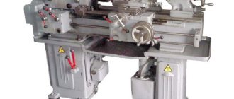
Metalworking machines 1A616 operate according to the following principle:
- Before processing, the part is fixed in the equipment chuck or between centers.
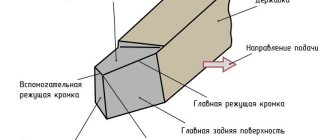
- The cutters are mounted in their holder on the support. No more than four cutting elements can be installed at the same time.
- To carry out the manipulation of drilling or cutting internal threads, a suitable tool is fixed in the tailstock quill.
- The main processing of the workpiece is carried out through a combination of translational-rotational movement of the cutter and rotation of the part. This design allows the processing of cylindrical, conical and shaped parts, including screw and end parts.
On the 1A616 metal lathe, the transmission of torque to the spindle and the workpiece is carried out using a belt pulley, which is placed between the supports. If necessary, the V-belt can be replaced without removing the spindle. The design of this equipment provides for the principle of separate transmission to the caliper. It can be moved using a lead screw or a roller. A DC starter is used in the motor winding, providing effective braking of the drive.
Caliper structure
A lathe support is a unit that ensures the fixation of the cutting tool, as well as its movement in the inclined, longitudinal and transverse directions. It is on the support that the tool holder is located, moving with it due to a manual or mechanical drive.
Support with carriage for machine Optimum D140x250
The movement of this unit is ensured by its structure, which is characteristic of all lathes.
- The longitudinal movement, for which the lead screw is responsible, is performed by the caliper carriage, while it moves along the longitudinal guides of the frame.
- Transverse movement is performed by the upper - rotating - part of the support, on which the tool holder is installed (such movement, due to which the depth of processing can be adjusted, is carried out along the transverse guides of the support itself, which are shaped like a dovetail).
Quick-change tool holder MULTIFIX cartridge type
The tool holder, also called the cutting head, is installed on the top of the support. The latter can be fixed at different angles using special nuts. Depending on the need, single or multiple tool holders can be installed on lathes. The body of a typical cutting head has a cylindrical shape, and the tool is inserted into a special side slot in it and secured with bolts. There is a protrusion on the bottom of the cutting head that fits into a corresponding slot on the support. This is the most typical tool holder mounting scheme, used primarily on machines designed to perform simple turning work.
Lathe spindle 16K20. Lathe spindle repair
The spindle is one of the critical parts of the machine, the accuracy and rigidity of which determines the quality of the operations performed on the machine. Deviations from the shape and dimensions of the spindle surfaces are allowed within a very narrow range, therefore increased requirements are placed on the repair of spindles. The specifics of repairing the ends of spindles that have a conical hole and thread, a landing journal or a cone for mounting technological equipment have been determined. If during repairs the dimensions of the surfaces of the spindle end are changed, then the technological equipment supplied with the machine will need to be changed or altered. Therefore, during repairs, they strive to restore it to its original dimensions, especially for the surfaces of the spindle ends.
The choice of method for restoring the main surfaces of the spindle is made depending on the amount of wear.
When the spindle surfaces are worn down to 0.05 mm per side, preliminary grinding is first performed to restore the geometric shape of the surfaces and chrome plating, after which they are finally ground, removing a layer up to 0.03 mm per side.
The surfaces of the spindles, which have wear of more than 0.05 mm per side, are subjected to metal build-up using one of the known methods, and then to mechanical processing.
During restoration, the conical hole at the end of the spindle is usually ground, then the end of the spindle is trimmed to a conical gauge. The end of the spindle flange is also trimmed after restoration by grinding the conical journal at the end of the spindle.
During repairs, the threads of spindles are usually cut to a full profile, and non-standard nuts for them are made anew.
When restoring spindles, it is necessary to choose repair methods that, in parallel with restoring the original dimensions, would ensure an increase in the wear resistance of the surfaces.
A repair drawing of a lathe spindle is shown in Fig. 27. In table. 14 shows the technological route for repairing the spindle.
Recommendations for choosing a cutting mode
Let's consider a few more common cases and those standard and practice-tested solutions that are acceptable and rational to use in these situations.
Lathe spindle speed is too high
Even the minimum amount for equipment can be excessive. Most often this is observed when they try to process some material of increased strength with a large-diameter blade. You can do the following:
- Replace the tool with one that is made of carbide metal and has a coating that protects it from heating at elevated temperatures.
- Adopt HSM technology, according to which the first pass is performed along the entire length of the edge, and subsequent passes only a quarter; This will speed up the production process without increasing wear or the likelihood of breakdowns.
- Reduce the diameter of the cutter, which will slow down the dynamics of the circumferential movement.
Feed speed is too slow
If the drive consistently does not provide the required labor productivity, you can take one of the following solutions:
- Take a cutter with a larger cross-section - the advice seems banal, but in practice, many beginners neglect such a seemingly simple solution.
- Reduce the number of shaft revolutions until the power reaches the lower tolerance limit, that is, follow the “slow but sure” principle.
- Taking a tool with fewer teeth is important for viscous materials, as it makes it easier to remove chips; Instead of three passes, give preference to one, and thereby triple the feed to the cutter.
Waste build-up when milling aluminum parts
This metal has a low melting point and therefore remains in significant quantities on the surface of the heated edge. Beginners often solve this issue by slowing down the technical process, but this significantly reduces labor productivity, and the production of blanks is more expensive.
Therefore, you need to do something differently, namely, review the composition of the cutting fluid, and if it is normal, then use it in a larger volume. If the equipment, in principle, does not consume coolant, it is necessary to implement one of the alternative solutions, for example, removing chips using a vacuum method or periodically blowing the contact area with compressed air.
Deep Hole Machining
This category includes those whose depth is 6 times greater than the diameter. In this situation, it is not so much the number of spindle revolutions that is important (the formula for calculating it has not changed), but rather the specifics of the operation. To prevent the blade from breaking or moving off the axis, you should:
- use a drill with parabolic flutes, not a milling cutter;
- supply coolant constantly and under pressure - the lubricant can effectively flush out chips;
- periodically remove the tool - just to remove the removed material;
- solve the problem sequentially, using two cutters of different diameters - go through the first half with the narrower one, the second with the wider one;
- speed up the process so that the waste flows in a continuous spiral.
How to mill grooves
To do this, it is necessary to correctly correlate the depth and width of the chips with the productivity of the equipment. You already know how to calculate spindle speeds, which means you can easily calculate the speed if you have data on the diameter of the cutter.
Therefore, let's focus on other patterns. For example, based on the fact that immersion into a part contributes to a more uniform distribution of loads, but it also increases the bending of the edge and impairs waste removal. Well, increasing the width leads to slower processing, which means production losses.
The optimal combination in this case is found experimentally: it is necessary to test the equipment in a variety of modes and find the one that can best meet the release conditions. An important point: the test workpiece must be identical to the “real” one in everything, including the material used. Only this approach will ensure the necessary accuracy of the results.
Now that you know everything about the issue, down to the unit of measurement of spindle rotation speed (rpm), you can calculate in advance what speed is needed to perform current technological operations and select the appropriate equipment. Responsible manufacturing plants design their machines taking into account the current needs of enterprises, including in the basic package a variety of tools, solutions and technologies for processing a wide variety of workpieces made of metal, plastic, and wood. This is exactly the approach professed by Izhevsk “Sarmat”, in whose catalog you will find a number of worthy models - reliable, easy to use, high-performance, economical.
Specifications
The parameters given in the technical data sheet help determine whether this is the device you need for work. We invite you to consider the information provided.
Main settings
- Type - screw-cutting, universal.
- Series - 1A616.
- Accuracy - N (normal).
- The height of the centers is 165 mm.
- The distance between centers is 710 mm.
Spindle
Shaft for securing the workpiece in the chuck:
- Speed limits (forward and reverse rotations) 9–1800 rpm (if necessary, can be ordered with speeds from 11 to 2240 rpm).
- Hole diameter 35 mm.
- Internal Morse taper N5.
- The spindle is braked and the handles are locked.
Caliper and feed
Caliper (support) - a movable element, a unit for securing cutting tools or workpieces:
- Tool holder - 4 cutters.
- Cutter holder (largest dimensions 20x25).
- From the supporting surface to the center line 25 mm.
- From the center axis to the edge of the tool holder 170 mm.
- One front caliper with one cutting head.
- Longitudinal max 670 mm (same values by hand, by roller and by screw).
- Transverse max 195 mm (by hand and with a screw, with a roller this is not possible).
For one dial division:
- Longitudinal 1 mm.
- Transverse 0.05 mm.
For 1 revolution of the dial:
- Longitudinal 110 mm.
- Transverse 5 mm.
Feeds - movement of a cutting element or workpiece in one revolution or working stroke:
In the machines of this series, the limits of longitudinal and transverse feed are set in the range of 0.065 - 0.91 mm/spindle revolution.
Cutting slide
One of the caliper elements. A holder for cutters is attached to it. It can be moved manually along the rotating part of the caliper.
- Maximum rotation angle 90°.
- Scale division, price 1°.
- Maximum movement 120 mm.
- One dial division, price 0.05 mm.
- One revolution of the dial provokes a movement of 3 mm.
Tailstock and frontstock
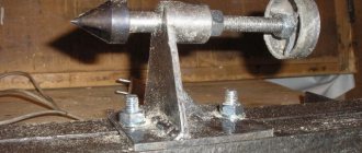
Tailstock is a unit that helps in supporting the part being manufactured. You can also attach a tool for external processing of the product in it. Under difficult working conditions, it is possible to secure the structure using a tightening bolt and nut.
- Internal Morse cone 4.
- The quill moves a maximum of 120 mm.
- One division of the quill movement scale = 1 mm.
- Lateral displacement 10 mm (forward and backward).
The headstock is a mechanism that moves, receiving impulse from the gearbox through belts and a relieved take-up pulley. Thanks to him it is possible:
- increase eightfold the transmission of motion between the feed and the spindle when cutting threads;
- cut right and left hand threads.
Electrical equipment
The machine operates with a main motion electric motor:
- Power 4 kW.
- 1450 rpm at 50 Hz.
- Power 0.125 kW.
- RPM 2800 at a frequency of 50 Hz.
Homemade spindle for CNC machine
Usually, Dremenl or its Chinese analogues are used as a spindle for a homemade CNC machine made by hand.
However, such milling cutters quickly become unusable, since they usually only have one thrust bearing and are not designed for large and prolonged lateral loads. But for a CNC router, such loads are a common occurrence, but what’s more, in fact, all milling is done with the help of lateral loads.
Purchased milling spindles use commutator motors. However, the commutators only work well at high rpm, while they have poor power at low rpm.
All this can be changed by installing a brushless motor!
- The photo above shows what a homemade CNC milling machine assembled with your own hands looks like, based on a budget CNC machine for a modeler, see the article, there are drawings of the CNC machine and recommendations for assembly.
- So, to make a homemade spindle for a CNC machine you will need:
- Brushless motor NTM series 50-50 580KV / 2000W Extended shaft Motor BC controller Servo tester
- However, you can use the cheapest servo tester - its task is to set the rotation speed of the motor, so its use is determined only by aesthetic taste and the convenience of attaching the servo tester to the CNC machine.
- On a CNC machine it all looks similar.
As you can see, the load is not transferred to the motor shaft, you can drive the router for as long as you like, but the motor will remain intact.
However, the long shaft allows you to use the cutter directly on the motor shaft using a collet clamp. Two bearings are installed on the motor shaft, mounted using a holder on the Z axis, the motor itself also has 2 built-in rolling bearings and mounting holes. This design will easily withstand the lateral loads that arise when milling the workpiece.
The spindle turns out to be very powerful, 2000 watts! It easily gnaws 8-piece plywood in two passes at a feed rate of 800; glued Kevlar with a thickness of up to 8 mm is cut with a 1.5 mm corn cutter at a feed rate of 200; at a higher feed rate, the cutter breaks. Easily handles aluminum and acrylic workpieces.
I saw how such a machine makes wooden dishes from birch, a souvenir of course, not Risoli branded, but plates for decorating walls or a sideboard (after painting and varnishing) are simply a sight for sore eyes!
It is worth adding that this controller has a built-in mode for holding speed regardless of the load, this is very useful for finishing.
As a result of this modification, you get the modernization of a homemade CNC machine at a low price. The rotation speed can be adjusted using a servo tester, the engine speed is maintained automatically by the controller. The quality of workmanship improves by an order of magnitude.
The cost of components for modifying a homemade CNC machine is 3.5 thousand rubles. This price is comparable to a new Dremel, but there is no way it can handle 8mm plywood, even at a feed of 100!
DIY CNC machine
Source: https://homecnc.ru/mech/68-samodelnii-shpindel-dlya-chpu-stanka
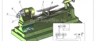
Machine gearbox design
The gearbox in this lathe model includes:
- 3 cylinders located one behind the other with 3 bearings;
- 3 single gears that form two active gears.
These units provide rotation of the axis, through the shaft, gear-type working transmissions. If it is necessary to set an increased speed of the axle, it is connected directly to the shaft using a claw coupling.
Regulation requires sequential manual actions:
- Determining the cutter holder into the desired position;
- Adjusting the position of the tailstock of the unit;
- Caliper control (main module).
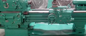
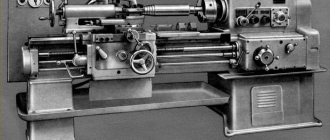
How the bed and headstock of the machine are arranged
The frame is a supporting element on which all other structural elements of the unit are installed and fixed. Structurally, the frame consists of two walls connected to each other by transverse elements that give it the required level of rigidity. Individual parts of the machine must move along the bed; for this purpose, it is equipped with special guides, three of which have a prismatic section, and one has a flat section. The tailstock of the machine is located on the right side of the bed, along which it moves thanks to internal guides.
The cast lathe bed is reinforced with stiffening ribs and has ground and hardened guides
The headstock simultaneously performs two functions: it gives the workpiece rotation and supports it during processing. On the front part of this part of the lathe (it is also called the “spindle head”) there are gearbox control handles. With the help of such handles, the machine spindle is given the required rotation speed.
In order to simplify the control of the gearbox, next to the shift knob there is a plate with a diagram that indicates how to position the handle so that the spindle rotates at the required frequency.
Speed selection lever for BF20 Yario machine
In addition to the gearbox, the headstock of the machine also contains a spindle rotation unit, in which rolling or sliding bearings can be used. The device chuck (cam or drive type) is fixed at the end of the spindle using a threaded connection. It is this unit of the lathe that is responsible for transmitting rotation to the workpiece during its processing.
The frame guides along which the machine carriage moves (the lower part of the support) have a prismatic cross-section. They are subject to high demands on parallelism and straightness. If these requirements are neglected, it will be impossible to ensure high quality processing.
Tailstock
The support unit designed to support the workpiece in alignment with the spindle head is called the tailstock. The tailstock includes a quill - a movable device that is moved along the axis of the workpiece using a screw driven by the feed flywheel.
The numbers indicate:
- Feed handwheel.
- Body fixing eccentric lever.
- Quill lock.
- Tailstock housing.
- Pinol.
- Center.
- Technological holes.
- Body base.
- Body transverse movement bolt.
Before starting work, it is recommended to move the tailstock towards the spindle and check their alignment visually. In case of doubt, one end of the test rod (workpiece) is clamped in the spindle head, and the second end is supported with the center of the tailstock moved into place. Then a rigidly fixed micrometer is moved along the frame guides along the entire length of the rod. The probe of the device must touch the rod - this is how the axial runout of the workpiece is checked. If runout exists, then thin adjustment plates are placed under the base of the tailstock, trying to reduce the axial runout to minimum values or to zero.
The tailstock can serve not only as a supporting element, but also as a holder for some types of tools. Drill, tap, internal cutter - many of these items can be mounted in a quill.
The inside of the quill is machined to a Morse taper, so the tool shanks must also have this taper. The design of the tailstock is made in such a way that when rotated back, the quill is retracted into the body to a certain depth. At this time, the end of the screw moving it rests against the end of the tool inserted into the quill. In this way the tool is pushed out of the quill.
The simplicity of the tailstock design does not eliminate the need for its adjustment, tuning or repair.
After long-term operation or as necessary, the tailstock is inspected. In the case of repairs, after completing all the necessary work or replacing parts, the tailstock is adjusted, which is called adjustment.
When performing any work on adjusting and tuning metal-cutting machines, adjustment plates made of wood are not used because of their softness.
Design features
Milling machines are installed in private workshops and industrial buildings. Nowadays, CNC options have become extremely popular, since the supplied control unit automates the processing process and significantly increases accuracy. The design of the spindle of a machine for milling work differs slightly from the corresponding unit of turning equipment, since in the first version the purpose is to secure a tool, in the other - a cylindrical workpiece. In addition, the chuck for the CNC spindle is made with greater accuracy, since a slight deviation will cause a loss of accuracy.
When analyzing what a spindle is and how it works, you need to pay attention to the following points:
- The base is provided by an iron shaft with very high axial load resistance.
- The specialized design that is designed to hold the cutter is provided by the combination of a mandrel and a collet.
- The possibility of a good fit of the mandrel can be eliminated by making the spindle in the shape of a cone.
- The modern design of a machine for milling work takes into account the location of the spindle on a specialized carriage, which can move in three coordinates at once. This ensures greater functionality and productivity. In this case, the drawing can be very complex.
- The circular motion is applied directly to the cutter. Many precision equipment does not have intermediate components, which significantly reduce the efficiency criterion and may cause rotational distortion.
- The most basic parameters are power and rotation speed.
The design features determine that the spindle structure of the machine for milling work makes it possible to install very different attachments. This moment significantly expands the scope of use of the device.
Main parameters of VMS
The main parameters: engine power and torque, rotation speeds, permissible cutting forces, were assigned based on an analysis of the processing modes of steel and aluminum workpieces with face, long-edge, end, disk cutters, as well as boring, drilling and thread-processing tools (drills, reamers, cutters and etc.). Hard alloy and ceramics were used as tool materials. When choosing processing modes, we took into account the fact that when accelerating the above-determined rotation speeds, a gap may arise in the conical connection of the mandrel and spindle, which must be eliminated. The main parameters of the VMS developed within the framework of the state contract are presented in the table.
Fig.5. VMS HSK 100 (longitudinal section)
In Fig. Figure 5 shows the design of a VMS with a HSK-A100 cone. The rotor 1 of the electric motor is installed with interference to transmit torque to the spindle 2. The influence of the electromagnetic fields of the motor is reduced by rings 3 made of non-magnetic material, which can also be used for balancing. Spindle 2, together with the electric motor rotor and other rotating parts, is balanced until a residual imbalance is achieved, at which the center of gravity of the spindle shifts by no more than 1...2 µm. The stator 4 with a cooling jacket 7 is installed in the VMS housing 5 and is cooled when liquid is supplied to the cavity 6 of this jacket. The same system is used to cool the bearings. The front support of the spindle is double angular contact ball bearings 8 and 9, the tension in which is provided by springs 10 (at high rotation speeds) and pneumatic cylinder 11 (at lower frequencies and higher loads). The tool is installed in a mandrel 12, which is secured using a clamping mechanism 13 on the spindle, based in a connection 14 of the HSK-A type. The release of the mandrel 12 is carried out by supplying oil under pressure into the right cavity 15 of the hydraulic cylinder 16, the movable body of which is connected to the spindle 2 through the clamp 17. Thus, when the mandrel 12 is released, the axial force of the spring release is perceived only partially by the spindle supports. The angular position of the spindle is monitored by a sensor, which consists of a magnetized disk 18 mounted on the spindle and a reading head 19 mounted on the housing flange. The vibration sensors 20 and the movement of the front end 22 are located in the VMS housing. Temperature sensors are located in close proximity to the outer rings of the supports and in Fig. 5 are not shown. The coolant supply is carried out through the nozzles 23 or through the hole in the rod 24 of the clamping mechanism 13.
Common mistakes when choosing cutting modes
Very often, novice turners and millers do not coordinate speeds - this results in stress concentration on the edge, which means it increases the likelihood of tool breakage at such “critical” points and causes other problems.
There are two classic situations:
- Maximum speed with slow feed - this seriously reduces the quality of processing. In addition, the cutter will not remove the chips, but will only press on the surface, first only grinding it, and then causing burns; at the same time, not only acting idle, but even losing strength, because bending of the edge will be observed.
- The opposite situation results in the blade removing too much material and at the same time experiencing excessive stress, resulting in chipping and leaving scratches and other defects on what should be a smooth plane.
Therefore, in practice, it is necessary to calculate the spindle speed for each technological operation and, based on the results obtained, to correlate the feed rate in order to ensure not only speed, but also accuracy and safety of the process. Moreover, all values can be taken within a certain range - there is always room for tolerances. Remember that long-term use of the tool is a consequence of the correct approach, while unexpected breakdown is the result of mistakes made.
And universal advice - carry out processing in several stages: first rough, removing as much unnecessary metal as possible, then finishing, more slowly, and finally finishing - to polish the smallest irregularities.
Making the front (back) headstock
For a homemade machine, you can make a headstock with your own hands. Suitable:
- wooden board;
- thick plywood (10 mm);
- a metal sheet of small thickness that can be cut with metal scissors.
It is easier to make a headstock if a drill is chosen as the basis for the lathe. You need to make a stand with your own hands, where the drill will be fixed rigidly and its axis will be strictly horizontal.
Both centers of the headstocks must be firmly attached; this is an important condition. The tailstock should be able to move along the axis of rotation and be firmly fixed in the right place
Read also: Do-it-yourself workbench for a miter saw
The type of electric drive and its power are selected with your own hands, depending on the future purpose of the lathe. But the engine power should not be less than 250 W, otherwise nothing sensible can be turned on the machine.
Detailed video about the design of the headstock:
Selecting a spindle for a CNC milling machine
25.04.2019
The spindle is an important part of technological machines, in particular milling machines. This is the name given to a motor with a self-clamping chuck in which the cutting tool is fixed. The latter can be a milling cutter, drill, sharpening stone, etc.
The milling machine transmits torque to the spindle at high speeds. Therefore, the engine must be durable. However, this is, of course, not the only requirement. How to choose the right spindle for a CNC machine? Let's find out in this article.
Theory of the issue
A spindle is a shaft that serves as an intermediary between the processing machine and the workpiece in metal processing. The cutting element is attached to it using a Morse cone. In boring machines, drilling machines and milling machines, the shaft has an adjustable length and is driven manually or automatically.
Conventionally, spindles are divided into two groups depending on their power:
The first include small drills, drills, and hammer drills. Their design is simple, their service life is relatively short, and management is not difficult. They are used for working on home desktop machines.
Industrial spindles are necessary for long-term operation and are designed to withstand impressive loads. They are equipped with cooling systems and lubricant supply to areas with high levels of friction or heating.
Low-power household spindles are absolutely not suitable for production units. The reason is that they are designed only for tension and compression, but not for lateral loads. As the spindle speed increases, the motor windings heat up, which causes a decrease in power. As a result, the element burns out, requiring immediate replacement.
Selection criteria
Let's take a closer look at exactly what factors you should pay attention to when choosing.
Power
Selecting a spindle for a CNC machine begins with studying the power characteristics. There's no need to skimp here; We recommend following the rule: “The more, the better.” The power reserve is the key to proper operation of the spindle beyond the specified resource.
Please note the following selection tips:
- Drilling or engraving is possible using a spindle with a power of less than 600 W;
- work on wood or sheet metal is performed with a device with a power of 800 to 1400 W;
- For a CNC machine that requires daily operation, choose a spindle with a power of over 1500W.
The quality of engine operation also depends on the reliability of the machine itself. If your CNC router is worn out, chances are a new spindle will do little good.
Surface to be processed
Spindle power is selected depending on the type of material being processed. For plywood, chipboard, MDF, a shaft with a power of up to 3000 W is recommended, for wood and soft alloys (aluminum, bronze) - up to 6000 W.
Type of milling
The next criterion for choosing a spindle is the milling method. There are two of them:
In the first case, the shaft feeds slowly, but the cutter rotates very quickly. The high-speed method involves slow rotation and fast feeding. Power milling is used when you need to quickly remove a certain amount of material. High-speed - if the quality of part processing is more important.
The characteristics of the cutter are indicated in the technical documentation for the product. Parameters are set on a CNC machine before starting work. It is important to pay attention to them so as not to overload the shaft and get maximum equipment performance.
Cooling system
The presence and type of cooling system is another important selection criterion. It depends on it how long the machine can work without interruption.
Air cooling means blowing the spindle windings through an impeller provided on the housing. It has more disadvantages than advantages, for example:
- air cooling is ineffective when operating at low speeds;
- Along with the air, chips, dust, and dirt are sucked under the housing, causing the motor to become clogged.
A water (liquid) cooling system does not have such disadvantages, but it complicates the design of a CNC milling machine. It requires a reservoir of liquid, which is mounted on the body of the device. The tubes that supply and discharge water are not always easy to install in a machine with two spindles.
Water cooling is preferable because the liquid is supplied to the spindle evenly, at the same speed. It is prohibited to start the router engine until the pump is activated. Ignoring the rule will cause overheating of the windings and failure of the entire system.
Manufacturer
You can determine whether an element was made in the West or the East by its appearance. For example, Chinese models have a solid, closed body in the shape of a cylinder. The design is quite rigid, vibrations during metalworking are minimal. There are no impellers or other similar holes, making the shaft impervious to chips and dust. Among the disadvantages of Chinese products:
- high percentage of fakes and defects,
- the tendency of internal elements to corrosion (due to a primitive cooling system),
- Difficulty replacing bearings.
European spindles are of higher quality and more expensive. Characteristic features: reliable bearings, minimal radial runout. They are usually air-cooled, so they are almost not subject to corrosion and operate smoothly.
Inverter type
An inverter is a frequency converter that transmits torque from an electric motor to a shaft. Should have the same power as the motor and slightly higher output current (rated).
Spindle for CNC router: suitable models
For a unit assembled at home, you should not buy an expensive shaft. A spindle, which used to be, say, part of a screwdriver, is not suitable for an industrial machine. Below is a list of possible solutions that will facilitate the selection of a spindle for a CNC machine for metal or other material:
- Engraver / drill / drill.
Suitable option for soft materials - wood, plastic, bronze, copper. The power of the devices starts from 100 W.
Advantages: minimum noise, high-quality chuck clamping, minimal loss of torque at low speeds. During installation, it is important to align the part at the required level and correctly measure the runout of the cutter. Such a spindle will cost 1000-3000 rubles.
- DC motors.
More powerful, advanced devices for desktop work. Power – from 400 W, speed – up to 12000 rpm.
Pros:
- low beat,
minimum noise,
- standard chuck (collet ER11A).
- additional power source required;
- power allows you to use only cutters up to 4 mm;
- compatible only with soft materials;
- require good ventilation, cooling, blowing.
- Straight grinder.
These are professional milling cutters that process most known materials. They are noisy, maintaining speed is unstable, which complicates the processing of plastic; has low quality bearings. The operating mode without breaks is limited to 1.5-2 hours.
- Professional liquid cooling spindles.
A technique almost completely free of drawbacks. It works quietly because the device does not have an impeller. Often used for equipment located in unventilated or heavily dusty areas. The cost of such spindles starts from 10,000 rubles. Keep in mind that the inverter will cost you about the same price. Advantages of liquid-cooled spindles include:
- precise positioning on a CNC machine,
powerful torque,
- reliability,
- double the number of bearings,
- minimal runout.
Minuses:
- If you are in doubt about your choice of spindle for a CNC machine, contact our managers by phone or email: company employees will answer questions and help you decide on the most suitable element for your equipment.
Classification of spindles by type, size and diameter
There are various bases for classification. The first, and perhaps the main one, is what equipment the unit is intended for. Of course, different machines and electrical equipment require different instruments.
The second principle of differentiation is size. The devices come in different sizes, designed for industrial use and private use. In this regard, a variety of consumable parts are needed - larger and smaller. If you want to replace the spindle on your own machine, then when purchasing you must indicate the number of your equipment, name and year of manufacture (there may be different modifications).
Well, the last, but not intended, classification is by type. Shafts can be:
- Collector. This is a device that includes a high-speed collet roller. The main areas of use are milling machines, as well as engraving operations.
- Specialized for high speeds. They allow you to achieve significant metal processing speeds, therefore increasing productivity. But since good quality can only be achieved with great precision, high-speed models are used mainly only on CNC equipment. You can buy such machines on the website.
- Design with built-in cooling. The cooling system can be supplied through a part or liquid, or cold air. This increases the cutting speed and the degree of surface roughness, and friction becomes less, so wear also comes later.
There is another classification - by manufacturer. Of course, European production is more preferable than Chinese. In Europe, porcelain bearings are often used, which provide very positive performance.
Spindle type selection
Now let’s introduce specific varieties, note their advantages and characteristic features. They should be taken into account when selecting parts.
With built-in electric motor (electric spindles)
They:
- Contributes to the development of very high speeds. With standard 18,000 - 24,000 rpm, some models can also support operating speeds of 120 thousand rpm.
- They cut very well at high speeds.
- They have limitations in loads - it is dictated by the use of small ball bearings.
- Not suitable for reverse. The absence of such a function makes it very difficult to create some elements, for example, cutting threads.
- Cones or collet clamps are most often used as clamps.
Mechanical with external drive
They:
- Deal with much lower speeds. The standard can be considered from 300 to 8,000 rpm. This is due to the fact that it is quite difficult to set in motion all the bearings, gears and other elements transmitting movement
- Rigidity and load capacity are greater. Why? because you can use not only ball bearings, but also more stable ones - roller bearings. So such equipment can even be used for power milling of titanium or other strong metals.
- There is feedback - provided that a motor with an encoder is installed.
- Tool cones are used instead of collets - the latter do not meet the requirements for fixation rigidity.
DIY lathe headstock
The headstock for a lathe can be made independently without any problems.
For this purpose you will need:
- Wooden plank.
- Plywood, ten millimeters thick.
- A thin sheet of metal that is cut with special scissors.
It is much easier to make a headstock with your own hands if the basis of this device is an ordinary unnecessary drill. After this, it will only be necessary to make a stand, which will subsequently be the mounting platform for the drill, which has a strict horizontal axis.
The middle of the front and middle of the tailstock must be securely fastened, this is extremely necessary. For the tailstock, it is necessary to establish in advance the limits of the possibilities of wrapping along the axis and rigidly securing it in place.
The power of the electric motor should be selected independently, based on the purpose of the turning device. Although the engine power does not need to be less than 250 W. Otherwise, it will not be possible to turn out any necessary parts.
How to choose a spindle for a CNC machine
The milling spindle is the main element of any CNC machine. Its main task is to quickly and efficiently process workpieces. At the same time, it must be able to perform a wide range of processing operations and uninterruptedly perform its functions throughout its entire service life.
When choosing a CNC machine for the production of MDF facades, it is first of all important to determine the power of the electric motor of the milling spindle. Low-power motors with power up to 2 kW are also suitable for processing MDF or wood.
However, the time of the milling process will be proportional to the power of the milling spindle of the CNC machine. The feasibility of using such CNC machines on an industrial scale is questionable.
In order to cut an MDF panel in one pass, or perform profile milling of a facade, you will need a power unit with a power of about 5 kW. To use automatic tool change, expand the range of tools used, and be able to connect additional units, you will need a spindle with a power of 10 kW or more.
The spindle rotation speed when operating a CNC machine with milling and engraving tools for processing wood materials varies from 12 to 24 thousand revolutions per minute. If you plan to use additional units, then the spindle electric motor must withstand the load and operate without loss of power at speeds of 3-8 thousand revolutions per minute.
When selecting a milling spindle for a CNC machine, one should not forget about such parameters as reliability and durability. Some CNC machine operations can take several hours, and if in the middle of the process you need to replace the brushes of the commutator motor of the milling spindle, you can not only waste precious time, but also lose the cutter and damage the workpiece.
Modern milling spindles for CNC machines with an asynchronous motor on ceramic bearings (including their Chinese counterparts), with air or water cooling, have a margin of reliability and ease of maintenance throughout their entire service life. In addition, a set of additional options will help protect equipment from overheating, sudden overloads, and power surges in the network.
Application of CNC
Modern lathes, especially foreign ones, are numerically controlled. This allows for high processing accuracy.
The features of such machines are the following nuances:
- All moving parts of the machine are controlled by a mini control unit. The machine has a complex electrical circuit.
- All parameters of the CNC machine exactly comply with GOST and are also described in the equipment passport. Accuracy indicators, dimensions, and speed are indicated here.
- Machines of this kind can be used at home because they are small in size, but can withstand surprisingly high loads for their size.
- The equipment has an indication, as well as a display for entering information.
- Benchtop CNC machines are used for high-precision machining of small parts. At the same time, home production has a high profitability rate.
Important! Most of these machines are produced abroad, and therefore they do not comply with Russian GOST.
Where are CNC machines used?
Such equipment is distinguished by its versatility in use, which has a positive effect on its demand and popularity in the market. Such devices can be used to work with the following materials:
- Tree.
- Plastic.
- Composites and polymers.
- Thin metal.
- Rubber.
- Other materials.
The most popular today are CNC machines, which are fully automated and provide maximum precision in wood processing. Using such woodworking machines you can perform the following work:
- Sawing a tree.
- Cut the plywood.
- Perform precision grinding.
- Perform complex three-dimensional and shaped wood cuts.
- Make various building materials from wood.
In each specific case, depending on the functionality of such a device, its design and the components used will differ. That is why you need to first decide on the functionality of such equipment and, depending on this, choose one or another type and design for the independent production of a CNC machine.
Equipment advantages
If we talk about the advantages of self-made CNC machines, we note the following:
- Efficiency at work.
- Versatility of use.
- Possibility of simplified reconfiguration of equipment.
- Reliability.
- Affordable price.
Assembly instructions
We offer you fairly simple instructions for assembling a CNC milling machine, which will allow you to independently create such equipment for wood processing. This scheme involves the use of ready-made sets of components, which include specially selected elements for the manufacture of such equipment. However, nothing prevents you from finding or making all the components yourself, and subsequently you will not only be able to save significantly, but also make a machine that will fully meet your requirements.
Preparatory work
- First of all, you need to decide on the scheme according to which the equipment you have made will subsequently operate. The easiest way to start is to use an old milling or drilling machine. In such equipment, the working head with an installed drill is replaced with a milling attachment.
- Next, you will need to make your own or use a ready-made mechanism from a kit that allows the milling tool to move in three planes. If you are assembling such a mechanism yourself, it can be made from carriages from an old non-working laser printer. Such carriages will allow the movement of the working tool in two planes.
Subsequently, it will be possible to easily connect a computer or control unit with software to the completed mechanism, which allows you to completely set the trajectory of the milling working head. At the same time, we note that if you use a carriage from an old filter, then you can only use such a CNC machine for processing wood, plastic or thin sheet metal.
If you need a CNC machine capable of performing full milling of workpieces from various materials, then a powerful stepper motor must be responsible for moving the working tool used. It can be done from a conventional electric motor or purchased ready-made low-power models.
The use of such motors will avoid the need to use a screw drive, which complicates the entire design. At the same time, the characteristics of such homemade equipment and its functionality are significantly expanded.
If for some reason you cannot or do not want to use a powerful stepper motor, then we recommend choosing carriages from printers of powerful top models, which will ensure the maximum possible amplitude of movement of the milling working head.
Scheme and drawings of the machine
The basis of a self-made CNC machine will be the milling mechanism. In the event that you use ready-made kits for performing such equipment, then you can select a mechanism that will fully correspond to the engine power and the subsequent work performed with wood and other materials.
On the Internet you can find numerous schemes for the implementation of such milling mechanisms for CNC machines.
In each case, the mechanism used will vary depending on the installed motors and carriages.
When choosing one or another design of such a milling machine, you need to give preference to equipment that combines simplicity of design and at the same time fully meets your requirements.
Assembling a CNC machine
First of all, it is necessary to construct the base of the equipment, to which the milling cutter, carriage and electric motor will subsequently be fixed. Such a base can be made from rectangular beams to which metal guides are welded or bolted.
The completed base for the machine must be rigid, which is necessary for accurate positioning of the milling head. Experts recommend connecting all metal elements of such a supporting structure using screws, which allows you not only to ensure the required strength, but also to easily upgrade your machines in the future.
The completed CNC machine must have a mechanism that allows the working tool to be moved in a vertical plane. We can recommend using a screw gear for such vertical movement of the tool, the rotation of which is transmitted using a toothed belt.
The vertical axis that every self-made CNC machine will require can be made from an aluminum plate. The dimensions of such a vertical axis should be exactly adjusted to the overall dimensions of the device you are assembling.
Having manufactured or purchased all the components for such equipment, you can begin assembling the machine. You need to mount two stepper motors that are attached to the base behind its vertical axis.
The first electric motor is responsible for moving the head in a horizontal plane , while the second ensures the movement of the cutter vertically.
The components and assemblies used are mounted, and due attention should be paid to the quality of their fixation.
During operation of such equipment, it is subject to increased load with vibration, and if the fastening is poor, problems with the accuracy of positioning of the heads may soon begin. The drive of all moving elements and working milling heads must be carried out exclusively using belt drives.
Selection of stepper motors
Most models of self-made CNC machines are equipped with stepper motors that allow you to move the working tool in three planes. Depending on the design, such equipment can be equipped with two or three stepper motors, and can also be additionally equipped with electric motors from computer printers.
When choosing the stepper motors to use, you need to pay attention to the number of control channels. The best models have five control channels, which increases the functionality of the manufactured mini-machine.
Also, when choosing specific models of such motors, you should familiarize yourself with their specifications and clarify by how many degrees the position of the head on the coordinate table changes in one step of the motor.
The positioning accuracy of the cutting tool will directly depend on this characteristic.
Electronic equipment
Today on sale you can find various ready-made microcircuits for controlling the operation of propulsion engines. It will also not be difficult to find appropriate software that will supply control signals to the motors, and, accordingly, they will lower and raise the working tool by changing their position.
An important point in choosing software is that it must support the drivers for the arduino controllers installed on your mini-machine. The control board is connected directly to a homemade CNC machine via the LPT or CNC port.
Headstock device
The main component of the front tank is the spindle. The spindle head is fixed to the left edge of the bed. This is the most important detail of the entire structure.
Various necessary fixtures, tools, and mandrels are fixed in the inner conical hole of the spindle.
How does it work
The movement of the spindle is transmitted from the V-belt pulley. All shafts and the spindle itself are mounted on rolling bearings.
When the machine rotates in a forward direction, large torques are required. This occurs due to the large number of discs that are located on the left side of the friction clutch.
If the gearbox is fixed in the bed frame, then it is connected to the spindle by a belt drive. Such equipment models are called split-drive machines.
Design and principle of operation
A desktop router with numerical control is a complex of mechanical equipment and an electronic subsystem. The part is processed by a rotating cutter that cuts off a layer of material. It is mounted in a chuck on the spindle shaft. The cutting part has a shape and size appropriate for the task. Rotational movements are created by a spindle electric motor located on a movable portal. The CNC controller sets commands for moving the portal along three coordinate axes, fixing the cutter at a point, and performing a processing operation.
The electronic component of desktop milling machines includes an operator panel, display, controller, and memory devices. The computer creates a program from G-codes based on a three-dimensional model of the product; the controller, reading the description, gives commands to the equipment.
Control is possible from a personal computer or laptop with an expansion card. The operator has the ability to set modes and control the machine manually.
Work on the equipment consists of securing the part, installing the cutting tool, installing the desired program, starting and monitoring the work process. Debugging can be done using a virtual run of the program to avoid errors during workpiece processing.
The following CNC machine software is used:
- Positional. The program specifies the coordinates of the points to be processed and is used for drilling and boring.
- Outline. The cutter moves within a given path.
- Combined. Combines positional and contour programs, significantly expanding processing capabilities.
- Multi-circuit. The most complex software designed for large-format machines.