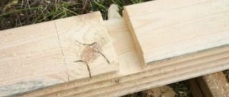
Key material
For the manufacture of keyed joints, calibrated rolled metal is used.
The most commonly used steel is grade 45. It is a regular type of carbon steel, which is often used to produce high-strength parts. The steel is used in the form of a 1 m long bar. In some cases, grade 50 carbon steel can be used. It is necessary when increased strength properties of the resulting keys are required. Less commonly used are alloy steels, for example, grade 40x, which is characterized by a high hardness index achieved by heat treatment.
Steel blanks are processed using cutters, drilling machines, chopping machines, grinders and other tools. The machines used have a control unit that allows, using numerical programs, to produce a part with the required parameters.
The price of the resulting key is quite low, so purchasing the necessary part is quite easy. But in some cases, when there is an urgent need to obtain a key, you can make it yourself. Most often, such a need arises in agriculture, where during seasonal work breakdowns often occur that need to be repaired. At the same time, the nearest points of sale of the necessary parts are located at a distance of several tens of kilometers.
With a small amount of tools on hand and a blank made of the appropriate material, you can quickly make a temporary replacement. If the technical specifications are observed, the resulting part can fully replace the factory one, but it is best to purchase a key of the required strength and geometric parameters at the first opportunity. This is necessary to avoid premature wear of the mechanisms.
It is better to use different types of wood as a material; for a dowel, a softer material than the main one is suitable. This will protect the main structure from damage in case of increased load. It is easier to replace a key than a large structural unit.
To prevent moisture from penetrating into reinforced concrete structures, special dowels called waterstop are used. They are made from high quality rubber and PVC. This allows you to achieve the required degree of waterproofness and resistance to solutions of aggressive chemicals.
Application
The main application of keyed connections is mounting on a shaft using a grooved connection. In most cases, the keyway resembles a wedge. This type of connection of parts allows the shaft and hub not to rotate relative to each other’s axis. The fixed position of the hub to the shaft with a key allows for high efficiency when transmitting force.
Most often, keyed connections can be found in mechanical engineering, during the construction of machine tools. It is often used in the production of cars and other mechanisms, where increased reliability of fixing machine parts is required. High reliability is achieved thanks to the function of the shaft safety unit with keyway.
The key acts as a fuse in cases where the maximum torque level is exceeded. In such cases, the key is sheared, absorbing the excessive load and removing it from the shaft and hub.
Due to its properties, it has become widespread in mechanical engineering; it is characterized by high efficiency, ease of manufacture and installation, and low cost. Such characteristics are especially important in industrial production, especially in agriculture. At the height of the season, there are often cases of breakdowns of individual components that need to be replaced as quickly as possible. Most often found in baler units.
Considering all of the above, the main positions for which a key is needed are highlighted:
- Ensuring the safety of connected nodes under increased loads.
- Achieving a high degree of fixation of individual elements of a mechanical assembly.
- Performs the function of preventing rotation of the unit and hub.
- The reliability of such a connection exceeds the reliability of analogues when fixing the shaft with parts.
In general, you can find a keyed connection in almost any complex mechanism, which is due to its technical characteristics.
Assembling keyed joints
Parallel keys must be replaced when:
- crushing of the side faces;
- weakening of the landing;
- collapse of the keyway.
Disassembly of a keyed connection can be done in various ways, depending on the design of the connection. To disassemble, make a threaded hole in the middle part of the key and screw a screw into it. When adjusting and assembling parallel keys, it is recommended to make a bevel on the surface of the key from the shaft side, to a length not exceeding the height of the key, and make a mark on the reverse side. An indispensable condition for the process of disassembling the key joint is maintaining the cleanliness and accuracy of the seats.
If the groove wall is slightly worn out, it is necessary to level the walls of the keyway until the correct shape is obtained and make a new key with an increased cross-section. Expansion of the keyway is allowed by an amount not exceeding 10-15% of the original size. When making a new key and repairing a keyway, processing should be carried out with the appropriate tool. Drilling of keyways must be done with a milling cutter.
Before assembly, the parts are cleaned and the fit dimensions are checked, the presence of nicks, burrs and other defects on the mating surfaces. Measuring the depth of the grooves, the height and correct installation of the keys is carried out using probes, templates, dial-type movement indicators and special stands.
The key is seated in the shaft groove with light blows of a copper hammer (or a soft metal hammer), under a press or using clamps. Skewing the key and cutting into the body of the groove is not allowed. The absence of lateral clearance between the key and the groove is checked with a feeler gauge, then the covering part (wheel, pulley) is installed and the presence of radial clearance is checked.
When assembling wedge keys, it is necessary to ensure that the key fits tightly to the bottom of the groove of the shaft and bushing and has gaps along its side walls. The upper edge of the wedge keys must be made with a slope along the length of 1:100. The slopes on the working surface of the key and in the groove of the bushing must coincide, otherwise the part will sit on the shaft with a skew. The accuracy of the key fit is checked with a feeler gauge on both sides of the bushing. During assembly, the grooves of the shaft or the surface of the key are sawed or scraped to prevent distortion and displacement. In the assembled connection, the head of the taper key should not reach the end of the hub by an amount equal to the height of the key. To prevent the wedge and tangential keys from falling out (when they are loosened), stops are installed on the screws at the heads. It should be noted the uncertainty of the forces that arise when pressing the wedge keys. This may damage the hubs of the male parts.
Dowels with a cross-sectional size of more than 28×16 mm must be checked for paint on the seats until five or more prints are obtained per square centimeter of surface. Before installing the key, the key and keyway must be cleaned and oiled. It is not allowed to install any pads in all types of keyed joints to achieve a tight fit of the keys.
Segmental keys are less susceptible to misalignment and do not require manual fitting (since the keyway is produced with a cutter corresponding to the size of the key); the groove for the segment key is deeper, which weakens the cross-section of the shaft.
In the assembled connection between the upper edge of the parallel key and the base of the hub groove (), the radial clearance must correspond to those given in the data. In connections with a wedge key (), the lateral clearance between the groove and the key should not exceed the values specified in.
Figure 4.1 – Gap when installing parallel keys
| Shaft diameter, mm | Radial clearance, mm |
| from 25 to 90 | 0,3 |
| from 90 to 170 | 0,4 |
| over 170 | 0,5 |
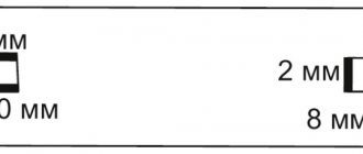
Figure 4.2 – Gaps when installing wedge keys
Table 4.2 – Lateral clearance values for wedge keys depending on the key size
| Normal dimensions of keys, mm | Side clearance, mm |
| b = 12…18; h = 5…11 | 0,35 |
| b = 20...28; h = 8…16 | 0,4 |
| b = 32…50; h = 11…28 | 0,5 |
| b = 60...100; h = 32…50 | 0,6 |
The guide keys are installed with additional fastening in the groove with screws; a looser fit is made in the groove of the moving parts.
How to make a dowel
But how to make a dowel from improvised materials? After all, factory products are made on high-precision equipment. Many enterprises for the manufacture of keys use drilling, grinding, grinding and many other types of CNC machines, the presence of which allows them to achieve the most accurate tolerances. It's actually not that difficult! Of course, it will not be possible to make a key as it came from the factory - one way or another, it will probably have slight deviations. However, for an emergency replacement, such a solution is fully suitable. In addition, for these purposes you can hire an experienced craftsman who already knows how to make a key. You will only need to provide him with payment, the required dimensions and raw materials for the blanks. True, many craftsmen always have their own keyed steel for such cases.
Since the keyed connection as a connecting link can have a variety of types of keys, when manufacturing the product it will be very important to take into account both what material can best withstand the given loads and what its configuration should be. Thus, it is possible to make a key exactly like the previous one, but use the most high-strength alloys in order to significantly extend its life and avoid premature failures
To make a key, you will need clean-drawn steel with the required dimensions: width, thickness, length
Please note that the bars can be rectangular or square. In this case, the length of the workpiece can vary from several meters to several centimeters
In addition to this, you will also need to prepare:
Please note - making a key requires compliance with safety regulations! First, you must make sure that the keyed steel is firmly secured in the vise. The degree of reliability of fixation must be checked periodically as all stages of work progress.
Secondly, under no circumstances should you use files that already have cracks and chips on the handle. Also, files without handles cannot be used. Thirdly, when filing workpieces with sharp edges, it is strictly forbidden to press your fingers under the file. In addition, it is strictly forbidden to remove chip dust with bare hands without gloves, since you can cut the skin or drive in a metal splinter. In addition, dust should not be blown off with your mouth, as it can easily get into the respiratory tract.
Key material
For the manufacture of keyed joints, calibrated rolled metal is used. The most commonly used steel is grade 45. It is a regular type of carbon steel, which is often used to produce high-strength parts. The steel is used in the form of a 1 m long bar.
In some cases, carbon steel grade 50 can be used. It is necessary when increased strength properties of the resulting keys are required. Less commonly used are alloy steels, for example, grade 40x, which is characterized by a high hardness index achieved by heat treatment.
Steel blanks are processed using cutters, drilling machines, chopping machines, grinders and other tools. The machines used have a control unit that allows, using numerical programs, to produce a part with the required parameters.
The price of the resulting key is quite low, so purchasing the necessary part is quite easy. But in some cases, when there is an urgent need to obtain a key, you can make it yourself. Most often, such a need arises in agriculture, where during seasonal work breakdowns often occur that need to be repaired. At the same time, the nearest points of sale of the necessary parts are located at a distance of several tens of kilometers.
With a small amount of tools on hand and a blank made of the appropriate material, you can quickly make a temporary replacement. If the technical specifications are observed, the resulting part can fully replace the factory one, but it is best to purchase a key of the required strength and geometric parameters at the first opportunity. This is necessary to avoid premature wear of the mechanisms.
It is better to use different types of wood as a material; for a dowel, a softer material than the main one is suitable. This will protect the main structure from damage in case of increased load. It is easier to replace a key than a large structural unit.
To prevent moisture from penetrating into reinforced concrete structures, special dowels called waterstop are used. They are made from high quality rubber and PVC. This allows you to achieve the required degree of waterproofness and resistance to solutions of aggressive chemicals.
Material
Steels with a carbon content of over 0.4% are most suitable for keys. It is this composition that provides the necessary values of wear resistance, strength and hardness. This includes structural steel grades 45 and 50, as well as ordinary quality steel St.6.
The use of more expensive analogues of steel alloys does not make sense, since the increased rigidity of the key increases the likelihood of shaft and hub grooves. To improve the conditions for transmission of rotation, it is much more profitable to use other more optimal ones.
Key. Keyway. Types, sizes and maximum deviations.
Parallel keys according to GOST 23360-78.
Fig. 1. Basic designations of parallel keys and keyways.
Table 1. Dimensions and maximum deviations of parallel keys and keyways according to GOST 23360-78.
| Shaft diameter d | Key section bхh | Keyway | Length l mm | ||||||||||
| Width b | Depth | Rounding radius r or chamfer s1 x 45° | |||||||||||
| Free connection | Nominal connection | Tight connection | Shaft t1 | Bushing t2 | |||||||||
| Shaft (H9) | Bushing (D10) | Shaft (N9) | Bushing (JS9) | Shaft and bushing (P9) | Nom.. | Nom. | Prev. off | no more | no less | ||||
| From 12 to 17 » 17 » 22 | 5×5 6×6 | +0,030 | +0,078 +0,030 | 0 -0,030 | ±0,015 | -0,012 -0,042 | 3,0 3,5 | +0,1 | 2,3 2,8 | +0,1 | 0,25 0,25 | 0,16 0,16 | 10-56 14-70 |
| St. 22 to 30 » 30 » 38 | 8×7 | +0,036 | +0,098 +0,040 | 0 -0,036 | ±0,018 | -0,015 -0,051 | 4,0 5,0 | +0,2 | 3,3 3,3 | +0,2 | 0,25 0,4 | 0,16 0,25 | 18-90 |
| 10×8 | 22-110 | ||||||||||||
| St. 38 to 44 » 44 » 50 » 50 » 58 » 58 » 65 | 12×8 | +0,043 | +0,120 +0,050 | 0 -0,043 | ±0,021 | -0,018 -0,061 | 5,0 | 3,3 | 0,4 | 0,25 | 28-140 | ||
| 14×9 | 5,5 | 3,8 | 36-160 | ||||||||||
| 16×10 | 6,0 | 4,3 | 45-180 | ||||||||||
| 18×11 | 7,0 | 4,4 | 50-200 | ||||||||||
| St. 65 to 75 » 75 » 85 » 85 » 95 | 20×12 | +0,052 | +0,149 +0,065 | 0 -0,052 | ±0,026 | -0,022 -0,074 | 7,5 | 4,9 | 0,6 | 0,4 | 56-220 | ||
| 22×14 | 9,0 | 5,4 | 63-250 | ||||||||||
| 24×14 | 9,0 | 5,4 | 70-280 |
Table 2. Limit deviations of dimensions (d + t1) and (d + t2).
| Height of keys | Maximum dimensional deviation | |
| d+t1 | d+t2 | |
| From 2 to 6 | 0 -0,1 | +0,1 0 |
| St. 6 to 18 | 0 -0,2 | +0,2 0 |
| St. 18 to 50 | 0 -0,3 | +0,3 0 |
Parallel keys with mounting on the shaft in accordance with GOST 8790-79.
Fig. 2. Basic designations of parallel keys with mounting on the shaft and keyways.
Table 3. Dimensions of parallel keys with mounting on the shaft according to GOST 8790-79.
| Width b (h9) | Height h (h11) | Rounding radius r or chamfer s1 x 45° | Diameter d0 | Length l2 | Length l (h14) | Screws according to GOST 1491-80 | ||
| no less | no more | from | before | |||||
| 8 | 7 | 0 25 | 0,40 | M3 | 7 | 25 | 90 | M3×8 |
| 10 | 8 | 0,40 | 0,60 | 8 | 25 | 110 | M3×10 | |
| 12 | M4 | 10 | 28 | 140 | M4×10 | |||
| 14 | 9 | M5 | 36 | 160 | M5×12 | |||
| 16 | 10 | M6 | 11 | 45 | 180 | M6×14 | ||
| 18 | 11 | 50 | 200 | |||||
| 20 | 12 | 0,60 | 0,80 | 56 | 220 | |||
| 22 | 14 | M8 | 16 | 63 | 250 | M8×20 | ||
| 25 | 70 | 280 | ||||||
| 28 | 16 | 80 | 320 | |||||
| 32 | 18 | M10 | 18 | 90 | 360 | M10×25 | ||
| 36 | 20 | 1,00 | 1,20 | 100 | 400 | |||
| 40 | 22 | M12 | 22 | 100 | 400 | M12×30 | ||
| 45 | 25 | 125 | 450 |
Segment keys according to GOST 8786-68.
Fig. 3. Basic designations of segmental keys and keyways.
Table 4. Dimensions and maximum deviations of segment keys and keyways according to GOST 8786-68.
| Shaft diameter d | Key dimensions b×h×D | Keyway | |||||||
| Transmitting torque | Fixing elements | Width b | Depth | Rounding radius r or chamfer s1 x 45° | |||||
| Shaft t1 | Bushing t2 | ||||||||
| Nom. | Prev. off | Nom. | Prev. off | no less | no more | ||||
| From 3 to 4 St. 4 » 5 | From 3 to 4 St. 4 » 6 | 1×1,4×4 1,5×2,6×7 | 1,0 1,5 | 1,0 2,0 | +0,1 0 | 0,6 0,8 | +0,1 | 0,08 | 0,16 |
| St. 5 » 6 » 6 » 7 | St. 6 » 8 » 8 » 10 | 2×2,6×7 2×3,7×10 | 2,0 | 1,8 2,9 | 1,0 1,0 | ||||
| St. 7 to 8 | St. 10 to 12 | 2,5×3,7×10 | 2,5 | 2,7 | 1,2 | ||||
| St. 8 to 10 » 10 » 12 | St. 12 to 15 » 15 » 18 | 3×5×13 3×6,5×16 | 3,0 | 3,8 5,3 | +0,2 0 | 1,4 1,4 | |||
| St. 12 to 14 » 14 » 16 | St. 18 to 20 » 20 » 22 | 4×6,5×16 4×7,5×19 | 4,0 | 5,0 6,0 | 1,8 1,8 | 0,16 | 0,25 | ||
| St. 16 to 18 » 18 » 20 | St. 22 to 25 » 25 » 28 | 5×6,5×16 5×7,5×19 | 5,0 | 4,5 5,5 | 2,3 2,3 | ||||
| St. 20 to 22 | St. 28 to 32 | 5×9×22 | 7,0 | +0,3 | 2,3 | ||||
| St. 22 to 25 » 25 » 28 | St. 32 to 36 » 36 » 40 | 6×9×22 6×10×25 | 6,0 | 6,5 7,5 | 2,8 2,8 | ||||
| St. 28 to 32 | St. 40 | 8×11×28 | 8,0 | 8,0 | 3,3 | +0,2 | 0,25 | 0,40 | |
| St. 32 to 38 | St. 40 | 10×13×32 | 10,0 | 10,0 | 3,3 |
Wedge keys according to GOST 24068-80.
Fig. 4. Basic designations of wedge keys and keyways.
Table 5.1 Dimensions and maximum deviations of wedge keys and keyways according to GOST 24068-80.
| Width b (h9) | Height h (h11) | Rounding radius r or chamfer s1 x 45° | Length l (h14) | Key head height | ||
| no less* | no more | from | before | |||
| 2 | 2 | 0,16 | 0,25 | 6 | 20 | — |
| 3 | 3 | 6 | 36 | — | ||
| 4 | 4 | 8 | 45 | 7 | ||
| 5 | 5 | 0,25 | 0,40 | 10 | 56 | 8 |
| 6 | 6 | 14 | 70 | 10 | ||
| 8 | 7 | 18 | 90 | 11 | ||
| 10 | 8 | 0,40 | 0,60 | 22 | 110 | 12 |
| 12 | 8 | 28 | 140 | 12 | ||
| 14 | 9 | 36 | 160 | 14 | ||
| 16 | 10 | 45 | 180 | 16 | ||
| 18 | 11 | 50 | 200 | 18 | ||
| 20 | 12 | 0,60 | 0,80 | 56 | 220 | 20 |
| 22 | 14 | 63 | 250 | 22 | ||
| 25 | 14 | 70 | 280 | 22 | ||
| 28 | 16 | 80 | 320 | 25 | ||
| 32 | 18 | 90 | 360 | 28 | ||
| 36 | 20 | 1,00 | 1,20 | 100 | 400 | 32 |
| 40 | 22 | 100 | 400 | 36 | ||
| 45 | 25 | 110 | 450 | 40 | ||
| 50 | 28 | 125 | 500 | 45 | ||
| 56 | 32 | 1,60 | 2,00 | 140 | 500 | 50 |
| 63 | 32 | 160 | 500 | 50 | ||
| 70 | 36 | 180 | 500 | 56 | ||
| 80 | 40 | 2,50 | 3,00 | 200 | 500 | 63 |
| 90 | 45 | 220 | 500 | 70 | ||
| 100 | 50 | 250 | 500 | 80 |
Continuation.
Table 5.2 Dimensions and maximum deviations of wedge keys and keyways according to GOST 24068-80.
| Shaft diameter | Key section bхh | Keyway | ||||||
| Width b | Depth | Rounding radius r or chamfer s1 x 45° | ||||||
| Shaft and sleeve (D10) | Shaft t1 | Bushing t2 | ||||||
| Nom. | Prev. off | Nom. | Prev. off | no less | no more | |||
| From 6 to 8 | 2x2 | 2 | 1,2 | +0,1 0 | 0,5 | +0,1 0 | 0,08 | 0,16 |
| St. 8 to 10 | 3x3 | 3 | 1,8 | 0,9 | ||||
| St. 10 to 12 | 4x4 | 4 | 2,5 | 1,2 | ||||
| St. 12 to 17 | 5x5 | 5 | 3,0 | 1,7 | 0,16 | 0,25 | ||
| St. 17 to 22 | 6x6 | 6 | 3,5 | 2,2 | ||||
| St. 22 to 30 | 8x7 | 8 | 4,0 | +0,2 0 | 2,4 | +0,2 0 | ||
| St. 30 to 38 | 10x8 | 10 | 5,0 | 2,4 | 0,25 | 0,40 | ||
| St. 38 to 44 | 12x8 | 12 | 5,0 | 2,4 | ||||
| St. 44 to 50 | 14x9 | 14 | 5,5 | 2,9 | ||||
| St. 50 to 58 | 16x10 | 16 | 6 | 3,4 | ||||
| St. 58 to 65 | 18x11 | 18 | 7 | 3,4 | ||||
| St. 65 to 75 | 20x12 | 20 | 7,5 | 3,9 | 0,40 | 0,60 | ||
| St. 75 to 85 | 22x14 | 22 | 9 | 4,4 | ||||
| St. 85 to 95 | 25x14 | 25 | 9 | 4,4 | ||||
| St. 95 to 110 | 28x16 | 28 | 10 | 5,4 | ||||
| St. 110 to 130 | 32x18 | 32 | 11 | 6,4 | ||||
| St. 130 to 150 | 36x20 | 36 | 12 | +0,3 0 | 7,1 | +0,3 0 | 0,70 | 1,00 |
| St. 150 to 170 | 40x22 | 40 | 13 | 8,1 | ||||
| St. 170 to 200 | 45x25 | 45 | 15 | 9,1 | ||||
| St. 200 to 230 | 50x28 | 50 | 17 | 10,1 | ||||
| St. 230 to 260 | 56x32 | 56 | 20 | 11,1 | 1,20 | 1,60 | ||
| St. 260 to 290 | 63x32 | 63 | 20 | 11,1 | ||||
| St. 290 to 330 | 70x36 | 70 | 22 | 13,1 | ||||
| St. 330 to 380 | 80x40 | 80 | 25 | 14,1 | 2,00 | 2,50 | ||
| St. 380 to 440 | 90x45 | 90 | 28 | 16,1 | ||||
| St. 440 to 500 | 100x50 | 100 | 31 | 18,1 |
MACHINING KEYWAYS ON SHAFTS
The most widely used in mechanical engineering are prismatic and segment keys.
Keyways for parallel keys can be through (Fig. 1.26, a),
closed on one side (Fig. 1.26,
b),
closed on both sides, i.e. blind (Fig. 1.27,
c).
Least technological
Rice. 1.26. Types of keyways:
a - through; b —
closed on one side (/—with a radius exit;
II—with
an exit under the end mill)
These are blind keyways. It is preferable to use through grooves and grooves closed on one side, but with a radius exit.
Technological tasks when processing keyways include requirements for the accuracy of groove width (according to IT9), groove depth (with a number of deviations: + 0.1; + 0.2; + 0.3), length (according to IT15). It is also necessary to ensure the symmetry of the location of the groove relative to the axis of the neck on which it is located.
The installation of shafts when processing grooves is usually done on a prism or in centers (Fig. 1.27).
When designing a technical route, the operation “milling the keyway” is located after turning the journal, before grinding it, since due to the removal of part of the material, the shaft seat is sometimes deformed.
Keyways are made in various ways, depending on the configuration of the groove and the type of tool used; they are performed on horizontal milling or vertical milling machines of general purpose or special ones.
Rice. 1.27. Keyway milling methods:
a - disk cutter with longitudinal feed; b—
end mill with longitudinal feed;
c
— key cutter with pendulum feed;
g
- disk cutter with vertical feed
Through keyways and closed on one side are made by milling with disk cutters (Fig. 1.27, a).
Milling of grooves is carried out in one or two working strokes. This method is the most productive and provides sufficient accuracy of the groove width.
The use of this method is limited by the configuration of the grooves: closed grooves with rounded ends cannot be made in this way; they are produced by end mills in one or several working strokes (Fig. 1.27, b).
Milling with an end mill in one working stroke is carried out in such a way that first, with a vertical feed, the cutter passes through the full depth of the groove, and then the longitudinal feed is turned on, with which the keyway is milled to its full length. This method requires a powerful machine, strong attachment of the cutter and abundant cooling. Due to the fact that the cutter works mainly with its peripheral part, the diameter of which decreases somewhat after sharpening, depending on the number of resharpenings, the cutter gives an inaccurate groove size in width.
To obtain precise groove widths, special key-milling machines with pendulum feed are used, working with double-spiral end mills with end cutting edges. With this method, the cutter cuts in 0.1...0.3 mm and mills the groove along its entire length, then cuts again to the same depth as in the previous case, and mills the groove again along its entire length, but in a different direction (Fig. 1.27, c).
This is where the definition of the method comes from - “pendulum feed”. This method is the most rational for the manufacture of keyways in serial and mass production, as it produces a completely accurate groove, ensuring complete interchangeability in the keyway connection. In addition, since the cutter works with the end part, it will be more durable, since it is not the peripheral part that wears out, but the end part. The disadvantage of this method is that it takes a significantly longer time to make a groove compared to milling in one working stroke, and even more so with milling with a disk cutter. This implies the following: 1) the pendulum feed method should be used in the manufacture of grooves that require interchangeability; 2) it is necessary to mill grooves in one working stroke in cases where it is possible to fit the keys along the grooves.
Through keyways of shafts can be processed on planing machines. Grooves on long shafts, for example, on the running shaft of a lathe, are planed on a longitudinal planer. Grooves on short shafts are planed on a cross-planing machine - mainly in single and small-scale production.
Keyways for segmental keys are made by milling using disk cutters (Fig. 1.27, d).
Keyways in the holes of the bushings of gear wheels, pulleys and other parts fitted onto a shaft with a key are processed in single and small-scale production on slotting machines, and in large-scale and mass production - on broaching machines. In Fig. Figure 1.28 shows the drawing of a keyway in a gear blank.
Rice. 1.28. Pulling a keyway through a hole
sa on a horizontal broaching machine. Blank 1
is placed on the guide pin
4,
inside of which there is a groove for guiding broaching
2.
When the groove is pulled in 2-3 working strokes, then a lining is placed under the broaching
3.
PROCESSING ON SPLINE SHAFT
Spline connections are widely used in mechanical engineering (machine tool building, automobile and tractor manufacturing and other industries) for fixed and movable landings.
There are spline connections of rectangular, involute and triangular profiles.
In the most commonly used spline joints of a rectangular profile, the mating parts are centered in three ways (Fig. 1.29):
- centering the bushing (or gear) along the outer diameter (D)
splined shaft protrusions;
— centering the bushing (or gear) along the internal diameter (d)
shaft splines (i.e. along the bottom of the cavity);
- centering the bushing (or gear) along the sides (b)
splines
D centering
the most technologically advanced, but its use is limited mainly to fixed spline connections
Rice. 1.29. Types of centering spline connections
concepts that do not require increased hardness. Centering at (d)
used in cases where spline connection elements are used for movable joints subjected to hardening.
applicable in the case of transmitting large torques with rotation reversal.
The technological process for manufacturing shaft splines depends on the method adopted for centering the shaft and bushing, i.e. whether the surfaces of the splines are heat-treated or not.
Let us give as an example the routes for processing splines on shafts, respectively, not subjected to and subject to heat treatment:
— rough turning, finishing turning and grinding of cylindrical surfaces for cutting splines, cutting splines, deburring and washing;
— rough turning, finishing turning, cutting splines with an allowance for grinding, milling grooves for the wheel to come out when grinding the centering surface of the inner diameter (if a cutter without whiskers is used in the first operation), heat treatment, grinding spline surfaces , deburring and washing.
Splines on shafts and other parts are made in various ways, which include: milling, planing (spline planing), broaching (spline pulling), rolling (spline rolling), grinding.
Milling of splines on shafts of small diameters (up to 100 mm) is usually carried out in one working stroke, and for large diameters - in two working strokes. Rough milling of splines, especially large diameters, is sometimes carried out with cutters on horizontal milling machines with dividing mechanisms.
You can mill splines using the method shown in Fig. 1.30, b,
allowing the use of cheaper cutters than the cutter shown in Fig.
1.30, a.
Rice. 1.30. Spline milling methods
A more productive method is to simultaneously mill two spline grooves with two special-profile disk cutters (Fig. 1.30, c).
Finish milling of splines with disk cutters is carried out only in the absence of a special machine or tool, since it does not provide sufficient accuracy in the pitch and width of the splines.
More precise milling of splines is carried out using the rolling method using a spline hob cutter (Fig. 1.30, d). Milling cutter
In addition to the rotational movement, it has longitudinal movement along the axis of the shaft being cut. This method is the most accurate and most productive.
The final processing of splines using the rolling method is carried out by finishing milling with worm spline cutters of a high accuracy class (AA and A).
When centering the bushing (or gear) on the inside diameter of the shaft splines, both the hob and the disc cutter should have "antennae" cutting grooves at the base of the spline to avoid galling at the inside corners; These grooves are also necessary when grinding on the sides and inside diameters.
Splining is carried out, as a rule, on special semi-automatic machines, which can work either separately or being built into an automatic line. This method most often processes through splines or splines that have an exit for cutters.
All splines are cut at the same time. In this case, processing is carried out by a set of shaped cutters installed with the ability to move in the radial direction. The number of cutters is equal to the number of grooves of the shaft being cut. The workpiece being processed is located vertically and is subjected to reciprocating movement along the axis. Before each upward movement of the workpiece, the cutters move towards the workpiece axis by the amount of the transverse feed. The working movement is to move the workpiece upward. When it moves downward, the cutters are retracted from the surface being processed to avoid friction with the workpiece. This process is highly productive and is used in high volume and mass production.
Spline planing provides surface roughness Ra
= 3.2…0.8 µm.
Spline broaching of through splines is carried out using chain broaches, the profile of which corresponds to the profile of the spline groove. Each groove is drawn separately, and a dividing device is used to process all grooves.
To process non-through splines, block broaches are used with independent installation and movement of the cutters in the radial direction (Fig. 1.31).
It is also possible to process splines using so-called female broaches. However, due to the complexity of the tool, this process is used relatively rarely.
Spline drawing provides a surface roughness of Ra= 1.6…0.8 µm.
Spline rolling without heating the part is carried out by rollers having a profile corresponding to the cross-sectional shape of the splines. Rollers rotating on axes (100 mm in diameter), one for each slot, are located radially in the segments of the massive knurling head housing (Fig. 1.32).
As the head moved, freely rotating rollers flew, pressing into the surface of the shaft, forming slots on it that corresponded to the profile of the roller. All splines are rolled simultaneously, without rotating the part.
On special machines for rolling splines, the rolling head is placed on a slide, for which shafts connecting two massive racks serve as guides. The slide is driven by a hydraulic cylinder located in the rear pillar. The front post contains a hydraulic chuck in which the workpiece is secured. Each roller is independently adjustable to the required height. The head as an independent unit is removed from the machine without disturbing the location of the rollers. It takes 5-10 minutes to change rollers, and about 30 minutes to set up the machine.
On such machines, the largest number of rolled splines reaches 18, the smallest is 8...10 (on shafts with a diameter of 16 mm). Longitudinal feed - up to 15 mm/s. The resulting pitch accuracy of the splines is 0.04 mm, non-straightness does not exceed 0.04 mm per 100 mm of length.
The rolling process is very productive, since all splines are rolled simultaneously, with little time, and with fairly high accuracy.
Grinding of splines is carried out in the following cases.
When centering spline shafts along the outer diameter, only the outer cylindrical surface of the shaft is ground on conventional cylindrical grinding machines; Grinding of the cavity (i.e. along the inner diameter of the shaft splines) and the sides of the splines is not used.
When centering spline shafts along the internal diameter of the splines, milling the latter gives processing accuracy along the internal diameter of up to 0.05...0.06 mm, which is not always sufficient for an accurate fit.
If spline shafts, after rough milling, have undergone heat treatment in the form of improvement or hardening, then after that they cannot be milled clean; they must be ground along the cavity surfaces (i.e., the inside diameter) and the sides of the splines. The most productive method of grinding with a shaped wheel (Fig. 1.33, a),
but at the same time, the grinding wheel wears unevenly due to the unequal thickness of the removed layer at the sides and the shaft cavity, so it is required
Rice. 1.33. Scheme for grinding splines on shafts: a—with a shaped wheel; b—c
two operations with one and two circles; c - three circles
frequent wheel adjustments. Despite this, this method is widely used in mechanical engineering.
You can grind the splines in two separate operations (Fig. 1.33, b); in the first, only the depressions are ground (along the inner diameter), and in the second, the sides of the splines are ground. To reduce wear on the grinding wheel, the shaft rotates after each table stroke, and thus the grinding wheel processes the depressions gradually, one after another.
Typically, the shaft rotates automatically after each double stroke of the machine table. But this method of grinding is less productive than the first.
To combine two grinding operations into one, machines are used on which the splines are grinded simultaneously with three wheels: one grinds the cavity, and the other two grind the side surfaces of the splines (Fig. 1.33, c).
In Fig. Figure 1.34 shows a diagram of dressing the shaped grinding wheel shown in Fig. with three diamond pencils. 1.33, a.
6.1.5.3. PROCESSING OF THREADED SURFACES ON SHAFTS
In mechanical engineering, cylindrical threads are used - fastening and running threads, as well as conical threads.
The main fastening thread is a metric triangular thread with a profile angle of 60°.
Running threads with rectangular and trapezoidal profiles are used; the latter are single-entry and multi-entry.
The thread can be external (on the outer surface of the part) and internal (on the inner surface of the part).
External threads can be produced with various tools: cutters, combs, dies, self-expanding thread-cutting heads, disk and group cutters, grinding wheels, rolling tools.
For the manufacture of internal threads, cutters, taps, sliding taps, group cutters, and knurling rollers are used.
One or another thread cutting method is used depending on the thread profile, the nature and type of material of the product, the volume of the production program and the required accuracy.
The main methods for shaping threaded surfaces, indicating the limits of the degrees of thread accuracy and roughness parameters, are given in Table. 1.3.
Thread cutting is carried out on thread-cutting and thread-milling machines and semi-automatic machines, nut-cutting machines, thread-rolling, thread-grinding, lathes and other machines.
Thread cutting with cutters and thread combs. External and internal threads can be processed on lathes. This is a low-productivity process, since processing is carried out in several working steps and requires highly qualified workers. The advantage of the method is the versatility of the equipment, tools and the ability to obtain high-precision threads. Lathes are used to cut precise threads on critical parts, as well as non-standard threads and large-diameter threads. To increase the accuracy of the thread, both roughing and finishing strokes are carried out using different cutters. There are two ways of cutting triangular threads: 1) radial feed movement; 2) feed movement along one of the sides of the profile.
The first method is more accurate, but less productive; therefore, it is recommended to make rough working moves using the second method, and finishing moves using the first method (Fig. 1.35, a).
To increase the productivity of thread processing, thread dies are used - round and prismatic. Usually the width of the comb is taken to be no less than six steps. When using combs, chip removal is performed by several teeth (Fig. 1.35, b) and the number of working strokes can be reduced to one.
For high-speed thread cutting, cutters equipped with a hard alloy are used, as well as sets of cutters (Fig. 1.35, c).
Rice. 1.35. Threading patterns:
a - with radial feed and with feed along one of the sides; b—location of the teeth of the threaded comb; V
- a set of cutters
Rice. 1.36. Thread cutting cutters:
a - prismatic; b
round; V -
with spring holder;
g - with a three-cutting head; d -
three-incisor plate
The designs of some types of cutters are shown in Fig. 1.36.
The cutters must be positioned strictly perpendicular to the axis of the machine, and their front surfaces must be located at the height of the centers of the machine. If they are in a different position, the thread will be cut with the wrong profile angle.
High demands placed on sharpening cutters and maintaining the correct profile led to the introduction into production of shaped thread cutters - prismatic and round (disc).
With these cutters, the dimensions of the thread profile elements are maintained more accurately than with conventional ones, since such cutters are sharpened along the front surface, and the rear surfaces obtained at the manufacturing stage remain unchanged.
The desire to relieve the workload of the finishing cutter and increase productivity led to the creation of combs. Combs, like cutters, are flat, prismatic and round and differ from cutters in that they cut simultaneously with several cutting edges. To divide the cutting work, the ends of the comb teeth are ground from one edge of the comb to the other, so that the cutting depth gradually increases.
Flat dies are used for cutting triangular threads with a small lead angle, tangential dies - with a large lead angle.
Round disc and prismatic combs, compared to flat ones, have the advantage that they are sharpened only along the front surface; allow a greater number of resharpenings and, therefore, have a longer service life.
Lathes are used for thread cutting mainly for:
— cutting threads on surfaces pre-processed on a lathe, thereby ensuring the correct position of the thread relative to other surfaces;
— cutting very precise long screws (in this case, a lathe operating with one cutter has an advantage over all other methods, including milling) when performing work suitable for a thread milling machine, when there is none or the batch size is small;
- cutting threads of large diameter, non-standard profile or pitch, as well as in general in all cases when the purchase of suitable dies and taps is not justified by the volume of production;
— cutting rectangular threads, the finishing milling of which is impossible, and the use of dies and taps, although possible, is difficult, especially when processing large workpieces.
The disadvantages of thread cutting on lathes include low productivity, which is inferior to other thread cutting methods, as well as the dependence of the accuracy of processing of the average diameter on the qualifications of the worker.
The use of combs makes it possible to slightly increase the accuracy, but even in this case it is usually lower than when cutting with dies and taps.
After cutting with a cutter, the thread is sometimes calibrated with precise dies (often manually).
Thus, thread cutting on a lathe is used mainly in single and small-scale production, and in large-scale and mass production - mainly for cutting long or precise threads.
In large-scale and mass production, thread cutting is used with rotating cutters, the so-called vortex method. In this case, the workpiece is fixed in the centers of a screw-cutting lathe or in a chuck. During operation, it rotates slowly. The cutter is fixed in a special head mounted on the machine support. The head, rotating at high speed from a special drive, is located eccentrically relative to the axis of the thread being cut. Thus, when the head rotates, the cutter fixed in it describes a circle whose diameter is greater than the outer diameter of the thread.
Periodically (once for each revolution of the head), the cutter comes into contact with the surface to be machined along an arc and for each revolution of the head cuts a crescent-shaped groove on the workpiece that has a thread profile.
For each revolution of the rotating workpiece, the head moves along the axis of the part by the amount of the thread pitch. The head is tilted relative to the axis of the part by the amount of the helix angle of the thread.
In whirlwind threading, the speed of the main cutting movement corresponding to the rotation speed of the cutter is V=
150…400 m/min, circular feed
S =
0.2…0.8 mm per revolution of the cutter.
In some head designs, four cutters are secured: two cutters cut the groove, the third forms the thread profile, and the fourth clears the burrs. The settings shown in Fig. 1.37, are calculated as follows:
where d -
outer diameter of the thread being cut; t is the depth of the thread profile.
Thread cutting with taps, dies and self-expanding threading heads is carried out on various machines. Internal threads are usually cut with machine taps on thread-cutting, drilling, revolving machines, as well as on aggregate machines, semi-automatic and automatic machines, depending on the scale of production. Machines must have fast reverse
Rice. 1.38. Threading tools:
a - die; b —
self-expanding threaded head
spindles for quickly changing the direction of the working movement to the opposite when the thread is cut.
For cutting threads with taps, various types of chucks are used: rigid, floating, self-switching when in contact with a stop, self-switching when overloaded with torque, etc.
Rigid cartridges are used on automatic and semi-automatic machines, as well as on CNC machines. If there is a large deviation from the alignment of the tap and the hole, floating ones are used.
In mass and large-scale production, prefabricated taps (threading heads) that can cut threads without reversing have become widespread.
External threads of low accuracy (7...8 degrees of accuracy) are cut with ordinary round dies. Dies with perfect cutting edges can be used to calibrate threads of the fifth degree of accuracy.
The main disadvantage of all types of dies is the need to screw them together after cutting, which reduces productivity and somewhat degrades the quality of the thread.
Dies are used to cut threads both manually and on various machines of lathe, drilling, and thread-cutting groups. Round dies (Fig. 1.38, a)
installed on machines in special chucks and secured with three to four screws. Cutting with dies is a low-productivity process.
Cutting external threads with self-opening threading heads is much more accurate, more productive and more accurate than previously discussed methods; he she-
Rice. 1.39. Thread milling schemes: a
— disk cutter;
b
- group (comb) cutter
is widely used in serial and mass production (Fig. 1.38, b).
Rotating heads are used on automatic lathes and semi-automatic machines.
Thread milling is widespread in serial and mass production and is used for cutting external and internal threads on thread milling machines (Fig. 1.39). It is carried out in two main ways: with a disk cutter (Fig. 1.39, a)
and a group (comb) cutter (Fig. 1.39,
b).
Cutting with a disk cutter is used when cutting threads with large pitches (P)
and round profile and mainly for pre-cutting trapezoidal threads in one, two or three working strokes. When cutting, the cutter rotates and makes a translational movement along the axis of the workpiece, and the movement per revolution of the workpiece must exactly correspond to the thread pitch.
A comb thread cutter is a set of several disc thread cutters. Complete cutting occurs in 1.2 revolutions of the workpiece (0.2 revolutions are required for complete cutting and covering the cutting point).
Disc milling is often used as roughing before cutting threads with a cutter.
Milling with a comb cutter is used to produce short threads with fine pitches. The length of the cutter is usually taken to be 2...5 mm greater than the length of the milled part. The group cutter is installed parallel to the axis of the part, and not at an angle, like a disk cutter. Cutting threads with a large helix angle with a comb cutter is difficult.
Thread milling is one of the most productive thread processing methods.
Grinding of threads is most often performed after heat treatment of the workpieces. Thread grinding can be external and internal, carried out on various thread grinding machines.
kah. There are the following methods for grinding threads: with a single-profile wheel; multi-profile circle with longitudinal feed movement; mortise; wide multidisciplinary circle.
Grinding with a single-profile wheel is a universal and precise method. It is used for the manufacture of taps, threaded plugs, threaded rings, etc.
Multi-profile wheels that grind threads with a longitudinal feed movement have a lead-in conical part. All threads of the grinding wheel are involved in processing, which is an advantage over plunge-cut grinding, as it increases productivity.
In mass production, a high-performance method of thread grinding is successfully used - centerless grinding.
Thread rolling (extrusion) is carried out by sequential or simultaneous copying by plastic deformation of the profile of a rolling threaded tool in a given area of the workpiece.
Rolling of external threads can be carried out using thread-rolling and special automatic machines in two ways: with flat dies (Fig. 1.40, a)
and knurling rollers (Fig. 1.40,
b - d).
In practice, thread rolling using rollers with radial longitudinal and tangential movements along the
dachas The most widespread method is rolling threads with two rollers (Fig. 1.40, c).
More productive is rolling with a tangential feed movement (Fig. 1.40,
d).
Machines operating in this way are called two- and three-cycle. The highest productivity is achieved by using multi-cycle thread rolling machines (Fig. 1.41).
Thread rolling in holes is carried out using chipless taps, rollers and rolling heads. When rolling internal threads in deep holes, a scheme with an axial movement of the roller feed is used.
Rolling can produce threads with a diameter of 0.3...150 mm on parts made of steel with hardness HB 120...340, as well as non-ferrous metals and alloys.
Varieties
The main criterion for choosing a parallel key is what type of connections it is intended for.
In the event that the connection is stationary, embedded parallel keys are used. In moving joints, guides or sliding feather keys are used. The use of guides is relevant when the hub moves along the longitudinal axis with the shaft, while it slides along the groove itself. The sliding type involves rigid fastening into a groove and movement along it.
In production, the production of keys of all types must be carried out in accordance with the relevant GOSTs. These documents contain recommended dimensions for products in accordance with standard shaft sizes.
In cases where the shaft or spindle has a non-standard diameter, detailed calculations of tolerances and fits for the groove should be carried out.
Types of keys
Modern production provides over 20 different types of items. But among them the following most used types in mechanical engineering are distinguished:
- Wedge - used on end installations and are a type of driving keys. This keyed connection is used for shaft diameters of 100 mm or more. Currently they are extremely rare. The reason for this lies in the high probability of overtightening of the unit and displacement of the alignment of the hub and shaft under the influence of one-sided force. It is also difficult to remove the keys.
- Prismatic. The groove dimensions are regulated by GOST 23360-78. They are most in demand in industry due to the optimal ratio of strength and manufacturability. There are two types of them: mortise and embedded. Mortise keys are installed with an interference fit, and embedded keys with a small gap.
- Guide keys. They are distinguished from prismatic ones by the presence of holes for fasteners on the shaft. In addition to transmitting rotation, they serve as an element for guiding parts.
- Segmental keys stand out from the rest due to their increased technology for cutting grooves. The grooves are made using disc cutters, which provides them with greater precision and productivity. The fastening of keys to shafts is also more stable due to deeper cutting into their surface. However, at the same time, all these advantages cause a significant weakening of the shaft. This circumstance, along with the short length of the groove, leads to the appearance of increased stresses, which limit the use of keys to lightly loaded products.
It is worth noting that keyways are made by milling and broaching. The most common way to produce them is with a finger cutter, since this method provides relatively favorable stress distribution and acceptable manufacturability.
Designations on the drawings
In the drawings, the designation of parallel keys is based on the GOST regulatory document. They are divided into keyways: high, normal height and guides. Their working faces are the lateral ones.
In the assembly drawing, the designation is made taking into account the shaft diameter, torque, cross-section and length.
For example:
Key 3–20Х12Х120 GOST 23360-78; Where 3 is the design, 20X12 is the section, 120 is the length.
Download GOST 23360-78
The designation of other types of keys in the images is carried out in the same way, based on the corresponding GOSTs developed for each individual model. The specified designation must clearly characterize the part, which is very important for obtaining a reliable connection. After all, even the slightest gap can cause rapid wear of working units and loss of efficiency during operation.
§ 33. Drawings of key and pin connections
GOST 29175-91
33.1. Image of keyed joints. One of the most common detachable connections of parts is keyed (see Fig. 209).
The key is designed to connect the shaft with the part mounted on it: a pulley, a gear wheel, a flywheel, etc.
In order for the pulley to rotate with the shaft, grooves (keyways) are cut into them, into which the key is placed.
Rice. 222. Keyed connection details
Figure 222 shows visual images of the keyed connection parts. The arrows show how they connect. In the visual illustration of a parallel key connection (Fig. 223), the bushing is shown in section so that the key is clearly visible. There are numbers on the shelves of leader lines. They correspond to the numbers assigned to the parts.
Rice. 223. Connection with a key
Drawings of the parts included in the connection are shown in Figure 224, and the assembly drawing is shown in Figure 225. Note that in the assembly drawing the key is shown uncut. As you know, this is done in the case when the cutting plane passes along a solid (non-hollow) part.
Rice. 224. Drawings of keyed connection parts
The drawing of parallel key connections shows a small gap - the gap between the top plane of the key and the bottom of the groove in the bushing.
Rice. 225. Assembly drawing of a keyed connection: 1 - shaft; 2 bushings; 3 - key
Each key on the assembly drawing has a symbol. For example, the entry Key 12x8x60 means that the parallel key has the following dimensions: width 12 mm, height 8 mm, length 60 mm. Recording key segm. 8×15 is read as follows: segmental key, thickness 8 mm, height 15 mm. Since the dimensions of the keys are standardized, therefore, the shape and dimensions of the keyways (grooves) on the shaft and in the bushing are standardized. These dimensions are selected depending on the diameter of the shaft included in the connection.
Table 4 (extracts from GOST 23360-78) shows the diameter D of the shaft, the corresponding dimensions of the keys (width b, height h) and the depth of the keyways (t for the shaft, t1 for the bushing).
Table 4. Prismatic keys (in mm)
For example, the shaft diameter is 18 mm. Using the table, we find the dimensions of the key. Its width b = 6 mm, height h = 6 mm. The length of the key l is chosen within the required limits. Let's take it equal to 30 mm. The depth of the groove on the shaft is t = 3.5 mm, the depth of the groove in the bushing is t1 = 2.8 mm.
Rice. 226. Reading drawing
- Using Table 4, write down the dimensions of the key and slots of the parallel key connection if the shaft diameter is 42 mm.
- Figure 226 shows the connection of the lever (part 1) with the shaft (part 2) using a key (part 3). Answer the questions: What do the two concentric circles indicated by the number 1 (circled) mean?
- What do the two horizontal lines mean, between which the arrow of the number 3 (in the circle) passes?
- What parts does the surface marked with number 2 (circled) belong to?
- Why are the surfaces marked 4 and 5 (in circles) not shaded? What details do they refer to?
- What part does the surface marked with number 6 (circled) belong to?
33.2. Picture of pin connections. Figure 209 shows a pin H that prevents the parts fastened with a screw from moving.
Drawings of cylindrical and conical pins are shown in Figure 227.
Rice. 227. Pin drawings
Figure 228 shows a visual representation, and Figure 229 shows an assembly drawing of a pin connection. The pin (item 3) is located in a hole drilled simultaneously in the housing (item 1) and in the shaft (item 2).
Rice. 228. Visual representation of a pin connection
Note that in assembly drawings, sectional pins are shown, like other non-hollow parts, to be uncut if the cutting plane runs along their axis.
Rice. 229. Assembly drawing of connection
The pin designation includes its name, dimensions and standard number, for example: Cylindrical pin 5×30. This means that the cylindrical pin has the following dimensions: diameter 5 mm, length 30 mm.
The entry Conical pin 10x70 means that the conical pin has a smaller diameter of 10 mm and a length of 70 mm.
A pin connection is sometimes used to prevent longitudinal movement of parts connected by a key (Fig. 230).
Rice. 230. Reading drawing
Look at the drawing (Fig. 230) and answer the questions:
- How many parts are included in the connection?
- Why are parts 3 and 4 not shaded?
- What are the dimensions of part 3, if it has the following designation: “Key 14x9x35”. Complete its drawing and technical drawing (see Fig. 224).
6.4.1. General information
A keyed connection is one of the common means of transmitting torque from a shaft to a bushing.
These connections are used in cases where there are no special requirements for the accuracy of centering of the parts being connected. Keyed connections can provide both a fixed and movable connection along the axis. According to their shape, keys are divided into prismatic, wedge, segment and tangential. More often than others, parallel keys with rounded ends are used, the so-called version 1 according to GOST 23360-78 (Fig. 6.19, a).
A groove is made on the shaft with a length equal to the length of the key (Fig. 6.19, b). To facilitate assembly operations, it is allowed to make the length of the keyway 0.5-1.0 mm longer than the length of the key. The keyways do not extend to the shaft end by a distance of L = 3.5 mm for shaft diameter Db ≤ 30 mm and L = 5.7 mm for Db > 30 mm. If there are several keyways on a stepped shaft, it is recommended to place them in different planes.
A keyway is drilled into the bushing (as a rule, along the entire length of the bushing) (Fig. 6.19, c).
The key is inserted into the groove on the shaft (Fig. 6.19, d). Then the bushing is put on the shaft so that the protruding part of the key fits into the keyway (Fig. 6.19, d). The depth of the groove should provide a gap K between the surface of the key and the groove (Fig. 6.20).
The transverse dimensions of the key b×h are linked to the diameter size Db of the shaft. The reference tables of GOST 23360-78 define the ranges of diameters (above Dmin to Dmax) of the shaft, for which the corresponding sections of the keys are established. The length of the keys l is also standardized. When working with the KOMPAS library, there is no need to look for this information in reference literature - all the data for construction is available in the library dialog boxes.
When depicting dowels on assembly drawings, they are shown uncut in longitudinal sections and dissected in transverse sections.
Rice. 6.19. Keyed connection elements:
a - parallel key with rounded ends;
b - keyway on the shaft; c — keyway in the bushing;
g - key inserted into a groove on the shaft;
d - keyed connection assembly (the bushing is shown with a quarter cutout)
On drawings of parts with parallel keys, the dimensions of the keyway on the shaft are usually indicated as in Fig. 6.21, a, and the keyway in the bushing - as in Fig. 6.21, b.
The following dimensions are considered mandatory:
keyway length Lp;
width b of the keyway of the shaft and bushing;
groove depth: on the shaft - size t1 and in the sleeve - size Db + t2;
diameters Db of the shaft and bushing bore.
Rice. 6.20. Key connection parameters
DIN 6885 B/P Prismatic steel key
- Modifications
- Description
- Specifications
- Your discounts
Parallel keys DIN 6885 are produced in different variations. They can be square, oval, with rounded corners on only one side, with or without holes, as well as with cuts in one of the corners.
The key is manufactured according to the German standard DIN 6885, as well as according to the Russian standard GOST 23360-78 and the international standard ISO 773. The DIN 6885 key is made of steel, by default it does not have an additional coating, and also does not have increased strength classes.
Installing a key in any mechanism requires care and experience in installing such products. To correctly install the key in the mechanism, you need to align the part and the shaft so that their grooves coincide. A key according to DIN 6885 secures the flywheel/gear/pulley mounted on it to the shaft. This shaft is often designed for thousands of revolutions per minute.
The unit in which the shaft rotates at such a huge speed most often works continuously for years. And all this time, the parallel key experiences shear forces.
Purpose
The key DIN 6885 is prismatic, or otherwise it is also called “keyway”. DIN 6885 keys are very often used in manufacturing and industrial applications.
Technical characteristics of the key DIN 6885 (part 1):
| Key parameters | Key width, B (h9) | ||||||||||||||||
| 2 | 3 | 4 | 5 | 6 | 8 | 10 | 12 | 14 | 16 | 18 | 20 | 22 | 25 | 28 | 32 | ||
| Height, H (h11) | 2 | 3 | 4 | 5 | 6 | 7 | 8 | 8 | 9 | 10 | 11 | 12 | 14 | 14 | 16 | 18 | |
| Radius | min. | 0,16 | 0,25 | 0,4 | 0,6 | ||||||||||||
| Max. | 0,25 | 0,4 | 0,6 | 0,8 | |||||||||||||
| Nominal length L | min. | 6 | 6 | 8 | 10 | 14 | 18 | 22 | 28 | 36 | 45 | 50 | 56 | 63 | 70 | 80 | 90 |
| Max. | 20 | 36 | 45 | 56 | 70 | 90 | 110 | 140 | 160 | 180 | 200 | 220 | 250 | 280 | 320 | 360 |
Technical characteristics of the key DIN 6885 (part 2):
| Key parameters | Key width, B (h9) | ||||||||||
| 36 | 40 | 45 | 50 | 56 | 63 | 70 | 80 | 90 | 100 | ||
| Height, H (h11) | 20 | 22 | 25 | 28 | 32 | 32 | 36 | 40 | 45 | 50 | |
| Radius | min. | 1 | 1,6 | 2,5 | |||||||
| Max. | 1,2 | 2 | 3 | ||||||||
| Nominal length L | min. | 100 | 110 | 125 | 140 | 160 | 180 | 200 | 220 | 250 | 280 |
| Max. | 400 | 400 | 400 | 400 | 400 | 400 | 400 | 400 | 400 |
| Order price | Discount amount for each order |
| 5,000 - 20,000 rubles | Basic wholesale price |
| 20,000 - 70,000 rubles | 5% discount |
| 70,000 - 200,000 rubles | 10% discount |
| over 200,000 rubles | Discount up to 25% |
If YOU are a large wholesale supply organization, there are special conditions for YOU, notify our managers and receive personal discounts!
Flat inner retaining ring for holes
Back
6.4.2. Example 24. Modeling a keyway for a parallel key
Model the keyway for the parallel key
in the central part of the shaft from the previous section (see Fig. 6.18).
1. Open the file with the shaft model.
2. Using the Library Manager button on the Standard panel, open the KOMPAS-libraries dialog box. Expand the Calculation and Construction section and in the right part of the window, double-click on the KOMPAS-SHAFT 3D item (Fig. 6.22).
Rice. 6.22. Connecting the KOMPAS-SHAFT 3D library
3. The KOMPAS-SHAFT 3D library will open (Fig. 6.23). Scroll to find Keyway for parallel key
and also double click to activate it.
Rice. 6.23. Calling the command Keyway for parallel key
4. In the document window, click on the cylindrical surface in the central part of the shaft on which the keyway should be built. This surface will be highlighted in aquamarine color (Fig. 6.24).
Rice. 6.24. Dedicated cylindrical surface for creating a keyway
5. In the Library Message dialog box, make sure that the External switch is selected and click OK (Figure 6.25).
Rice. 6.25. Library Message Dialog Box
6. After this, the Groove for parallel key dialog box according to GOST 23360-78 will appear (Fig. 6.26). The system will automatically determine the diameter Db and length Lb of the cylindrical surface. This data will be reflected in the table at the bottom of the window. The same table contains reference information: minimum Dmin and maximum Dmax shaft diameters of the standardized range, width b and depth t1 of the keyway, radius r of the interface of the bottom of the keyway with the side faces (or chamfer S1 ×45°).
7. In the upper left part of the dialog box, in the Key list box, the designation of the key 18×11×50 (b×h×l in mm) proposed by the system will appear. In this case, the key section 18×11 is automatically selected depending on
range Dmin—Dmax, which includes the shaft diameter Db. If you need to select a different key length l, expand the Key list and specify the required standard size (Fig. 6.27). In our case, a key length of 50 mm is acceptable.
Rice. 6.26. Dialog box Groove for parallel key according to GOST 23360-78
Rice. 6.27. Expanded list Dialog box key Groove for parallel key according to GOST 23360-78
8. The length of the keyway Lp must be equal to the length of the key l. Leave the Slot length Lp, mm field unchanged. In the Distance L, mm field, set the distance L from the base face to 5 mm, and in the Alfa Angle field, deg. — the angle of rotation of the groove relative to the vertical axis is 180°. Click the Specify Face button (the dialog box will temporarily collapse). In the document window, specify the base face relative to which the keyway will be constructed - this face will be highlighted in green (Fig. 6.28).
Varieties
The main criterion for choosing a parallel key is what type of connections it is intended for.
In the event that the connection is stationary, embedded parallel keys are used. In moving joints, guides or sliding feather keys are used. The use of guides is relevant when the hub moves along the longitudinal axis with the shaft, while it slides along the groove itself. The sliding type involves rigid fastening into a groove and movement along it.
In production, the production of keys of all types must be carried out in accordance with the relevant GOSTs. These documents contain recommended dimensions for products in accordance with standard shaft sizes.
In cases where the shaft or spindle has a non-standard diameter, detailed calculations of tolerances and fits for the groove should be carried out.