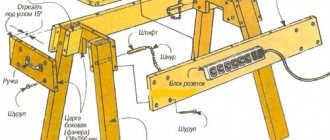
I sell wooden products online in my city. About 7 years ago I bought a good set of hand-held circular saws. There were a bunch of stops in this set; I also purchased several over the years. Now I realize that they have fallen into disrepair, and the circular itself is not in the best condition. I decided to order a new one and make the stops myself. So to speak, to check, at the same time, what I have learned over all these years. Having finished, I decided that it would be useful for you to learn about how to make stops for a circular saw.
Source ytimg.com
Do-it-yourself circular: safety of use
If you take into account how much a circular saw costs (from 16,000 rubles - the most modest model), and compare the price with the costs of making it yourself (this is 60-90% less), then the difference is significant.
But no savings will be justified if the safety of work is not ensured. Before starting to work on a circular saw, you must wear goggles and gloves.
In order to avoid traumatic situations, you should adhere to the following recommendations:
- do not use wood with metal inclusions (nails, angles, bolts, etc.) as raw materials;
- cutting boards larger than 200 cm must be done by two people;
- When using a circular saw, you should not make sudden movements;
- Before starting work, be sure to wear goggles and gloves;
- Wood waste should be removed from the surface of the circular saw, as it can cause a short circuit.
It is strictly forbidden to work on a homemade circular saw:
- if the guiding device is not made;
- no casing;
- there are no finger guards;
- the riving knife is higher than the saw blade.
To avoid hazardous situations when working with a circular saw, you should adhere to safety precautions
A good tool allows you to enjoy your work. And the result pleases with a high level of quality. Making a tool with your own hands will allow you to obtain the desired parameters and necessary performance characteristics. You cannot limit yourself to superficial knowledge in any type of activity, especially in a technical area. You should take on the task of assembling a circular saw yourself only after thorough theoretical preparation and a full understanding of the practical part of the process.
https://remoo.ru/instrumentyi/cirkulyarka-svoimi-rukami
Share the news on social networks
« Previous entry
Last checks
The previous operations performed will improve the quality of work on the circular saw, but it is also worth taking care of safety. Take a look at the riving knife, which should be in the middle of the disk and at right angles to the plane of the table. This is checked with a flat bar and the same drawing square.
The principle of adjusting the riving knife is similar for most sawing machines: loosen the nuts or screws, change the inclination of the stand and the outlet of the angle, then tighten the fasteners.
All that remains is to check the side wing extensions and, if necessary, align the parts at table level. Try to carry out such maintenance at least once a year and your “circular” will always be in good working order. And for cheap machines, such a check is recommended immediately after purchasing the equipment.
Peculiarities
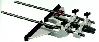
What these design solutions have in common is a rack that moves relative to the cutting blade along the plane of the saw table. When creating this rail, it is proposed to use a standard extruded profile of a rectangular unequal flange angular section of aluminum or magnesium alloys. When assembling a parallel miter gauge with your own hands, other profiles of a similar cross-section can be used in accordance with the length and width of the working plane of the table, as well as the type of circular saw.
The proposed drawing options use a corner with the following dimensions (mm):
- wide – 70x6;
- narrow – 41x10.
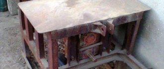
Making a circular saw
The machine consists of three main structural elements:
- base;
- sawing table;
- parallel stop.
The base and the sawing table itself are not very complex structural elements. Their design is obvious and not so complicated. Therefore, in this article we will consider the most complex element - the parallel stop.
So, the rip fence is a moving part of the machine, which is a guide for the workpiece and it is along it that the workpiece moves. Accordingly, the quality of the cut depends on the parallel stop because if the stop is not parallel, then either the workpiece or the saw blade may become jammed.
In addition, the parallel stop of a circular saw must be of a rather rigid structure, since the master makes efforts to press the workpiece against the stop, and if the stop is displaced, this will lead to non-parallelism with the consequences indicated above.
There are various designs of parallel stops depending on the methods of attaching it to the circular table. Here is a table with the characteristics of these options.
| Rip fence design | Advantages and disadvantages |
| Two-point mounting (front and rear) | Advantages: Quite rigid design, Allows you to place the stop anywhere on the circular table (to the left or right of the saw blade); Does not require the massiveness of the guide itself Disadvantage: To fasten it, the master needs to clamp one end in front of the machine, and also go around the machine and secure the opposite end of the stop. This is very inconvenient when selecting the required position of the stop and with frequent readjustment it is a significant drawback. |
| Single point mounting (front) | Advantages: Less rigid design than when attaching the stop at two points, Allows you to place the stop anywhere on the circular table (to the left or right of the saw blade); To change the position of the stop, it is enough to fix it on one side of the machine, where the master is located during the sawing process. Disadvantage: The design of the stop must be massive in order to ensure the necessary rigidity of the structure. |
| Fastening in the groove of a circular table | Advantages: Quick changeover. Disadvantages: Complexity of design, Weakening of the circular table design, Fixed position of the saw blade from the mowing line, Quite a complex design for self-production, especially from wood (made only from metal). |
In this article we will examine the option of creating a parallel stop design for a circular saw with one attachment point.
Preparation of blanks
It all starts with the fact that it is necessary to cut the workpieces to the specified dimensions.
- flat longitudinal elements are made from laminated chipboard, and not from solid pine, like other parts.
- Two blanks of clamping strips are made with “oblique” ends (not 90º, but 63.5º).
Thus, we get the following set of blanks.
First execution
A rail is taken from the above-mentioned corner with a length of 450 mm. For correct marking, this workpiece is placed on the tabletop of the circular saw so that the wide bar is parallel to the cutting saw blade. The narrow bar should be on the desktop on the side opposite the disk, as shown in the figure. In a narrow shelf (41 mm wide) of the corner, at a distance of 20 mm from the end, the centers of three through holes with a diameter of 8 mm are marked, the distances between them should be the same. From the mowing line, the location of the marked centers is marked at a distance of 268 mm by the line for the location of the centers of three more through holes with a diameter of 8 mm (with the same distance between them). This completes the marking.
After this, you can proceed directly to assembly.
- 6 marked holes with a diameter of 8 mm are drilled, and the burrs inevitably created during drilling are processed with a needle file or sandpaper.
- Two 8x18 mm pins are pressed into the outer holes of each triple.
- The resulting structure is placed on the work table in such a way that the pins fit into the grooves provided by the design of the circular saw table, on both sides of the saw blade perpendicular to its plane, the narrow angle bar is located on the plane of the work table. The entire device moves freely on the table surface parallel to the plane of the saw blade; the pins act as guides, preventing the stop from skewing and the violation of the parallelism of the planes of the circular disk and the vertical surface of the stop.
- From the bottom of the work table, M8 bolts are inserted into the grooves and middle holes between the stop pins so that their threaded part fits into the slot of the table and the holes of the rack, and the heads of the bolts rest against the lower surface of the table and are between the pins.
- On each side, over the rail, which is a parallel stop, an M8 wing nut or regular M8 nut is screwed onto an M8 bolt. In this way, rigid fastening of the entire structure to the desktop is achieved.
- both wing nuts are released;
- the rack moves to the required distance from the disk;
- fix the rail with nuts.
The rack moves parallel to the working disk, since the pins, acting as guides, prevent distortions of the rip fence relative to the saw blade.
This design can only be used if there are grooves (slots) on the work table of the circular saw on both sides of the disk perpendicular to its plane.
Making a laminate tire
This method of making a carriage for a circular saw with your own hands is the easiest to implement; it uses readily available raw materials.
Required:
- laminate sheet;
- several screws;
- A4 piece of paper.
Three blanks are made from the laminate. One of them will serve as the basis for the guide. The other two are cut in the shape of two strips, each about half a meter long. For both, the edges are aligned on one side using a milling cutter. Using self-tapping screws, the strips are attached to each other parallel to the straight edges. The width of the groove between them is checked using an A4 piece of paper, inserting it into the device and scrolling.
The tire is secured to the base of the circular saw using side support fasteners. If the warranty period of the saw has already expired, for greater reliability of fastening you can use the body of the circular saw by making an additional hole in it.
Before starting work, the homemade guide must be extended in front of the circular saw handle. In this case, it is necessary that the guide is covered by the nose of the sole by several centimeters. For perfect compatibility of the edges of the guide strips with the marks on the material, you need to carefully saw off the uneven strips with a laminate cutting disc.
From plywood
This is one of the simplest universal guide options for a hand-made circular saw, and therefore it is most common in home workshops. Let us consider in detail the process of its manufacture and the principle of operation.
Necessary materials
To make such a tire you will need three pieces of plywood 10 mm thick. Their length should be the same and is usually equal to the length of the workbench on which the work will be done. One of the segments should be 25-35 cm wide (it will serve as the base), the width of the other two will be determined during the manufacture of the tire. Also prepare 16 mm wood screws.
Drawing with dimensions:
Manufacturing instructions
When creating a guide, all dimensions must be observed very accurately. Small deviations can lead to a sharp deterioration in the result. If desired, laminate can be used instead of plywood.
The plywood guide rail is made in several steps:
- Measure the distance from the inner edge of the saw blade to the rip guide groove located on the tool support platform.
- Cut one of the plywood strips so that its width is 0.2-0.5 mm less than the distance obtained in step 1. The grains of the top layer of veneer on plywood should be directed longitudinally.
- Using self-tapping screws, screw the resulting strip to a wide piece of plywood (base), precisely aligning their ends. This will be the working edge of the tire.
- Using a caliper, measure the width of the longitudinal cut guide groove.
- Screw the remaining strip of plywood to the base parallel to the first strip. There should be a gap between them, the size of which should be 0.2-0.5 mm less than the width of the groove measured in the previous paragraph.
- To avoid damaging the material being cut, a layer of soft fabric is glued to the finished guide on the bottom side.
The homemade guide is ready, all that remains is to prepare the hand saw. To do this, saw off a narrow strip of thick plywood or other sufficiently durable material. The height of this strip should be 8-9 mm greater than the depth of the guide groove on the saw base. The width corresponds to the width of this groove. The length is several centimeters longer than the length of the sole.
The resulting limiter strip should be secured in the guide groove so that it protrudes beyond both edges of the sole.
How to use plywood tire?
To make a cut, you will need two clamps and two flat pieces of wood slightly thicker than the work piece. The guide rail is installed with its ends on these bars so that its working edge protrudes slightly beyond the edge of the workbench table top. In places where the tire rests on the bars, it is tightly fastened with clamps to the workbench.
The workpiece to be cut with a cutting line pre-marked with a pencil is placed under the tire, and the cutting line is aligned with its working edge. Finally, a circular piece with a limit strip attached to it is installed on the tire so that the limiter on the sole fits exactly into the prepared gap. Now you can saw, holding the workpiece with your free hand and lightly pressing the saw towards the workbench.
A simple carriage for a homemade circular saw
I will consider this option using the example of manufacturing a carriage for a desktop mini-circular machine J1F-DS100, which was previously converted. About this in this article
Considering that most craftsmen will make similar devices for other saws, in this case the manufacturing process itself and the design of the device (it is typical and common), and not the dimensions indicated in the attached drawing, are of interest.
Manufacturing sequence
So, in the manufactured machine we have a tabletop made of ordinary plywood.
(Don’t be confused by some difference in the size of the table top in further photos - I simply replaced the plywood with a slightly larger one, because I realized that the dimensions of this one were somewhat small)
Marking guides
In order to obtain a more or less usable tool in the future, it is necessary to accurately mark and mill the parallel grooves into which the carriage slides will be installed. The first necessary condition here is that they are parallel to the plane of the saw blade. To do this, you need to “beat off this line” on the surface of the tabletop as accurately as possible. If there is no play or wobble in the disk fit, then it is enough to firmly attach a metal ruler to the disk and draw the desired line.
Milling grooves for runners
Now, parallel to this line, you need to mill two grooves on either side of the saw blade.
To ensure a more or less stable position of the carriage, I approximately divided the tabletop into three equal parts and drew the required two lines. Parallelism is the most important condition here. You need to mill along the stop using any router. For this micro-machine I used an edge router.
Making runners
The runners can be made from hardwood, such as maple. I had oak on hand and sawed the slats from it. In general, if an aluminum U-shaped profile is inserted into the grooves, then the wear of the slides will be much less. I did without a profile due to the fact that I plan to buy a Proxon machine and the resource of this homemade product, provided that it is used infrequently, will be enough for me. Those who make homemade products “seriously and for a long time” keep this aspect in mind.
The slats should fit tightly in the grooves, but slide freely and not dangle in them. Otherwise, the carriage itself will dangle. The slats should be flush with the surface of the tabletop for ease of installation of the carriage platform on them.
Mounting the carriage base onto the skids
The next step is to install the carriage base on the skids. For this machine I take a 7 mm thick MDF sheet. Since I use PVA to install the base, I first stick masking tape on each edge of the slide to protect the surfaces from excess squeezed out glue.
Next, you can apply glue to the runners
and place the base blank on top of the runners, securing it with clamps at the gluing points
After the glue has dried, remove the carriage, remove the tape and check its sliding in the grooves
Marking the corners of the carriage
The carriage is installed in the grooves, the saw is turned on, and a cut is made in the front part of the base.
And relative to the line of this cut, the required 45 degrees are struck on both sides. This allows measurements to be taken from the actual position of the saw blade in the carriage cut.
Next, we cut down the corners and get the result as close as possible to the result.
Correction of carriage angles
We set the emphasis at any arbitrary distance from the disk and file 4 rough blanks
Putting them in a frame, we check the accuracy of the connection
At the slightest deviation from the correct angle, we trim the edge of the carriage on the desired side and again make a test fit, thus bringing it to the exact angle of 45 degrees.
After this, you can install the sides of the carriage flush with the cut of the base. From the rear side, we bring the edge of the carriage at a right angle to the saw blade, thereby ensuring the possibility of trimming parts at 90 degrees.
Templates and copy sleeve
The copying ring is a circle with a protrusion that slides along a template, guaranteeing accuracy of processing. The ring can be screwed to the base of the router or secured with antennae. The diameter of the device is selected so that it does not come into contact with the working part of the tool.
The ring template is fixed on the material being processed, firmly adhering to the tabletop. Reliable clamping is provided by double-sided tape and clamps. Having finished the part, you need to make sure that the sleeve fits tightly along the edge of the template when working.
A self-made template for a router can also be used for processing the corners of a part, when it is necessary for them to be round. Depending on the location and dimensions of the template, the radius size of the rounding can be any.
The template design often includes bearings or rings. If this is a ring, then it should be selected according to the size of the cutter. If there is a difference in diameters, it is necessary to add stops to the template design, with the help of which you can move the device away from the edge of the part.
Among the auxiliary devices for the router, the most flexible templates, in addition to processing the edges of the material, also allow you to cut complex grooves. The special design of the accessory makes it possible to effectively create recesses for door hinges. Using a template, you can even carry out decorative work with a router, for example, cutting out wooden patterns.
How to do it yourself?
Branded tires from manufacturers are made in such a way that their boundaries coincide with the line along which the cut occurs. Branded products are glued with a special tape, which prevents damage to the soft material. All these little things are convenient and necessary. This tire provides productivity, accuracy and comfort in work.
Such products also have their drawbacks: a branded tire may not always meet production tasks.
If you have to use the tool occasionally, then buying an expensive tire is not necessary. The best option: make the tire yourself. In terms of quality and functionality, such guides are often not inferior to the world’s best analogues.
To make a homemade tire, you need to take some durable material as a basis, it may be:
- corner;
- cross-cut pipe;
- metal guide;
- laminate.
The material should not deform under the influence of excess moisture or temperature changes.
Guide drawings can be found on the Internet. It’s easy to bring any sample you like to mind, adjusting it to the features of this equipment
It is important to observe all dimensions. Hand-held circular saws often have comfortable handles, which improves the quality of work and makes work much easier. Materials required to make a universal tire:
Materials required to make a universal tire:
- plywood or chipboard;
- epoxy adhesive;
- self-tapping screws
The tools you will need are:
- clamps;
- turbine;
- protractor ruler;
- fine sandpaper;
- marker.
For small circular saw
It is made in the form of a rail miter box. The following items are required:
- building rule (2 meters);
- clamps;
- propylene fragments;
- corner or profile made of aluminum;
- wooden bars 12 mm;
- chipboards;
- laminate.
For big
Items you will need:
- metal corners of the same parameters;
- strong wooden base (chipboard sheet, board up to 3 cm thick);
- bolts and nuts.
The markings are being prepared; the places of future fastening should be indicated. The immersion board must move freely parallel to the guide elements; the disk must not be at too high a height.
From building regulations and fasteners
To make such a knot, you will need the following elements:
- building rule (1.5–2 meters), which is used for plastering walls;
- clamps (their number depends on the attachment points);
- guides, which are made of rules, clamps and polypropylene elements.
The creation algorithm is as follows:
- handles are removed from the rule (if present);
- Adapters are cut from dense PVC material; they should be slightly larger than the depth of the groove of the rule itself;
- the completed structure is attached to a wooden block.
Made of aluminum
To make a tire from an aluminum profile, you will need the following elements:
- profile "P";
- fastening fittings;
- sheet plywood (you can take waste).
You will also need the following tool:
- drill;
- wrenches;
- ruler or tape measure.
Made of wood
To create such a structure, two bars are used, the sizes of which vary. You can also use chipboard for these purposes. All wooden elements are fastened with self-tapping screws. The protruding parts are carefully cut off. Such a simple mechanism can also provide a perfect cut.
From profiles of different sizes
In this case, a small profile is installed in a larger profile. The created structure is attached to the base of the circular saw. This installation ensures the ability to move exactly along a given line. The edge at the base must be perfectly smooth; it ensures the quality of the cut. The profiles form rails, this allows you to significantly reduce the effort required to control the unit. The smaller profile should not have any gaps with the larger profile, but there should be free movement.
From laminate
This material is cheap, easy to buy, and quite technologically advanced. The laminate is cut into two identical fragments in the form of strips. One of them will be the main one, the second will be the auxiliary one. All edges are polished and rounded. Using self-tapping screws, the material is attached to the base.
To ensure comfortable operation, it is recommended to extend the tire to the maximum distance. Using a grinder, remove excess material from the guides.
Learn how to make a homemade guide bar for a circular saw in the video below.
Using a rail miter box
The use of a rail miter box is advisable if you need to quickly and efficiently process a large number of boards. Used in production:
- two identical metal corners;
- Chipboard or plywood sheet at least 1.5 cm thick for the base;
- four pairs of bolts.
Metal corners are installed on a plywood base.
The corners are fastened with bolts - which act as studs - at the corners of the base. The corners are placed on the same plane strictly parallel to each other. This is necessary so that the circular saw slides freely along the rail during operation and does not jam or slide off it. Using pins, the fixing height of the corners is set, which is necessary for the free movement of the processed material between the base and the rails. In this case, the edge of the cutting circle should not be too high from the base, while at the same time eliminating the possibility of damage to it. To make the saw glide easier, fluoroplastic strips are glued to the corners or a frame with wheels is made for it, which is preferable.
The source material is cut into workpieces using a rip fence for a circular saw during operation. You can easily make it with your own hands from a wooden plank or a metal corner, securing it to a workbench with clamps.
Having made the markings on the workbench, the tire is set at the required distance from the stop and, resting the end of the board against it, the workpiece is cut off.
If it is necessary to cut the workpiece at an angle, it is fixed using a stop made of a pair of screws screwed into the base, and the angular inclination of the cut is set using a protractor.
Useful tricks and tips
There are such small devices that it is shameful to even consider them a tool. At the same time, they are great for cutting. These are the tricks of experienced masters.
Blank template
When cutting a large number of identical parts, you can use the first of them as a template for cutting subsequent copies. You just need to fasten a thrust piece on one side of the first sample with a width corresponding to the distance from the edge of the slab to the cutting disc. By installing such a template on the material to be cut, you can make many identical parts without markings.
Installation bars
The simplest part that makes it easier to install any stop and guide along the markings is a small cross-section block. There are cuts on it, the distance between which is equal to the segment from the end of the saw sole to the saw blade. Two such bars will help you install any guides quickly and accurately at the required distance from the marking line. All that remains is to secure the guide.
Pull-out protection
The protection can be any block whose width corresponds to the thickness of the workpiece being cut. If it is secured at the point where the saw blade exits the material being processed, it will act as a limiter and serve as protection against tearing out and chipping.
These devices are not limited to the range of useful homemade products that make working with a hand-held circular saw easier. These are the easiest to make. Others require time and skill. But craftsmen even make such a device as a protractor for a circular saw with their own hands. There would be a desire.
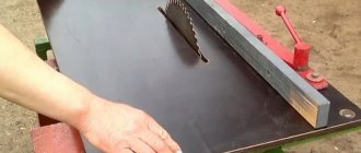
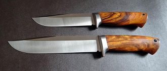
The circular fence and parallel stop are perhaps the main fixture on the circular table. That's why I decided to take this project seriously. I don’t spend extra time on sanding and shaping without the need for rounding on fixtures, I consider cutting, gluing, fastening with self-tapping screws and it’s done. In my opinion, extra beauty is not often appropriate, but strength is always needed. When working with difficult projects, I break them down into smaller components and work separately with it. Having at my disposal a narrow duralumin parallel stop (photo on the right), I had a number of inconveniences. The problem is that for each new cut you need to change the size of the stop installation; for this purpose, by moving the stop, we take into account the dimensions at the point where the cut begins to cut the workpiece and at the point where the cut exits relative to the saw blade, then we secure it with 2 handles. It's awkward and wastes time.
Step 1: Making the stop.
Cut three strips of laminated chipboard 1.1 m long and 8 cm wide, and then assemble them together to form a U-shaped profile. Using the internal dimensions of the profile, make 5 blank inserts for rigidity and insert them into the inside of the profile; they will create a square section required by the stop. The advantage of this stop is the ability to use it on both sides of the saw blade (photo on the left).
Step 2.7: Making a guide channel for the stop.
The channel guide for the stop is made of two slats, has the shape of a U-shaped profile and is bolted to the end of the circular table, perpendicular to the saw blade.
Making a stop for a circular saw
There are 2 types of cutting stop: parallel and angular. Each option has its own characteristics that you need to know about before manufacturing.
Angular
The angle stop for the machine is used quite often. With its help, boards are cut accurately and quickly at right angles. It is also used for trimming boards from which the stop is made. You can easily make a device for sawing at an angle with your own hands.
- Take a sheet made of plywood for the base. Its thickness should not exceed 1 cm.
- Attach a guide bar to the base, the height of which is no more than 2 cm.
- It is recommended to fix the stop at the bottom, which is perpendicular to the guide. It must be made from the same piece of material.
- Separate unused parts of the bar. The distance from the guide to the saw blade is calculated individually each time, so it is recommended to attach it to the material being processed from the corner with clamps.
- Use fastening devices made of wooden washers.
- Press the wing nut onto the screw.
Circular saw accessories and their purpose
Today, a carpenter can both make and buy various products that make his work easier. Additional devices to make working with the saw easier are divided into several types. The main ones are:
- Parallel stop.
- Guide rail for sawing sheet blanks.
- Device for perpendicular cutting and facing.
- Installation bars for precise placement of the guide.
- Adjustable guide for cutting workpieces at a fixed angle.
Using them will significantly reduce time and reduce labor costs when working with massive and large-sized products.
Circular saw stop
First of all, it is necessary for sawing wood products along the grain to a certain width. However, its design has one significant drawback. To ensure safe operation of the saw, it is designed not to come into contact with the guard when working, so cuts cannot be made beyond a certain width. This parameter varies among different saw models and manufacturers.
Before work you must:
- Lock the stop at the desired cutting width.
- Secure the workpiece.
- Press the edge of the fence against the board and guide the saw along the workpiece.
Guide bars for circular saws
The guide bar is a long strip of plywood on which an aluminum u-shaped profile is screwed, which serves as the actual bar along which the saw itself runs directly. The main task is sawing sheet material. The tire is installed on top of the workpiece, aligned along the cutting line. Then it is secured with clamps. When working, the saw should be guided along the guide.
Circular saw blade
It is an aluminum or wooden board with a cut in it for the disk to operate. Attached to the saw base with screws. Used to prevent chipping when cutting plywood or chipboard.
DIY rip fence for a circular saw
It is preferable to make this product from chipboard, since this material is more resistant to wood - in terms of humidity.
The board itself consists of several strips of chipboard or boards, namely four, fastened with self-tapping screws along the entire length along the contour. A semblance of a massive ruler in the form of a box is formed. It is attached to a support board, which ensures its fixation to the tabletop. At the other end there is an eccentric handle. There is a metal runner that ensures smooth sliding of the stop during operation. The stop position is adjusted using bolts that come into direct contact with the table top.
DIY guide bar for a circular saw
It is intended to be used as a stop for the product when cutting. It is a wide board to which a metal corner is attached with screws along its entire length. A saw is placed at the top of this corner of the guide, moving freely along the entire length. Allows smooth cutting of various materials.
DIY ruler for a circular saw
For the ruler you will need several pieces of 12 mm thick plywood, as well as a 20 mm square aluminum profile. A groove is made on the edge of the plywood. The profile along the entire length of the sheet is screwed onto self-tapping screws. The stiffener is screwed to the side using self-tapping screws. Before screwing, the stiffening ribs should be bent slightly to the base of the bending ruler. This is necessary to securely fix the ruler on the part so that it does not “dance.” In addition, a platform is made with a cut-out groove for the guide and for the disk from the same 12 mm thick plywood. It should move freely along the guide.
DIY circular saw carriage
To make a carriage with your own hands, we will need a sheet of chipboard. We bolt two metal corners to it - these are guides. We measure a perpendicular from the saw and place a stop for the carriage. In addition to all this, you can make an additional curved groove in the base of the board at 45 degrees for cutting at an angle.
With the help of these auxiliary tools, any carpenter will make his work easier. At the same time, the speed and productivity of labor will increase.
https://youtube.com/watch?v=Ud5lpoe2ehM
Rip fence
A regular rip fence for a circular saw is a good example of how a small addition can make a big difference. Almost every hand-held circular saw is equipped with a rip fence for longitudinal cutting of a given width. This is a really useful device.
The standard stop has one drawback. For safety reasons, it is set to values that allow it to be used to make cuts less than 20–25 mm wide. This is done so that the stop does not interfere with the movement of the saw guard. But it is enough to attach a wooden block with self-tapping screws to the parallel strip of the standard stop - and its capabilities will increase, while the minimum cutting width will not be limited in any way.
Note! We must remember about safety - when making cuts of less than 15 mm, the block does not allow the protective casing to cover the saw blade.
Additional accessories
- Blank template. If it is necessary to manufacture parts of the same type, you can use one of them as a guide template. To do this, a workpiece of the required length is cut and a thrust strip is attached to one end. The width of the rail must match the working distance. When working with this device, the thrust bar must fit snugly against the end of the workpiece. This way you can get a large number of parts of absolutely the same length without spending time marking the cutting line.
- Cutting square. For permanent use, you can make a cutting square. It consists of two massive wooden or plywood slats fastened with overlapping screws in the shape of the letter “T”. The length of the protruding ends of the “T” crossbar is adjusted to match the working distance of the circular saw. Positioning the aligned end of the crossbar against the marking line will allow for an accurate perpendicular cut.
- Edge stop. The standard configuration of the circular saw includes an angular (edge) stop. It allows you to make cuts parallel to the edge of the material being processed. Using a self-made edge stop, due to the expanded and longer base, you can get a cleaner and more accurate cut.
To make an edge stop, a stop strip and a base for a circular saw are cut out of 15 mm thick plywood. Keyways are selected in the base and thrust rack using a hand router. The dowels themselves are made from scraps of hard wood or from the same plywood and are attached to the grooves of the thrust strip. To strengthen the stop at an angle of 90°, another rail of sufficient width is attached to the stop rail, which will rest on the workpiece. Adjusting the distance of the cut from the edge of the workpiece is carried out by moving the stop bar along the guides and then fixing it using a locking screw.
To install the screw, a through groove is sawn through the base. To increase cutting accuracy and improve work safety, it is recommended to use two screws. A hole is made in the base plate for the saw blade and a mounting system for the circular saw is installed. The design of the fastening system can be very diverse and will depend on the specific brand of saw. The common point for all options should be reliable fixation of the circular saw and the ability to remove it from the device after finishing work. To make it easier to set the required cutting width of the material, a measuring tape is attached to the front surface of the base of the device.
Step-by-step instruction
So, the design details and the necessary tools have been selected, you can begin assembling and subsequent installation of the homemade carriage.
Step 1: Attaching the aluminum profiles
Since the carriage will “run along the saw table,” the first thing to do is guide grooves. To do this, take two U-shaped profiles, approximately equal to the length of the table. You can adjust the dimensions using a grinder.
At the same distance from the location of the cutting disc, circular saws draw two lines parallel to it. Then, using a hand router, U-profile holes are cut out along them, chips are blown out of them, and the corrugated pipes are secured in them using glue. After the glue dries, the grooves are ready.
Step 2: Making the carriage base
Next, the mobile base of the cross-cutting carriage is constructed. To do this, take two strips, which in thickness fit freely into the U-shaped groove. But there is one point here - the carriage will have to “slide” freely on the table, and for this it is raised above the table by 2-3 mm. To do this, nuts of equal thickness are placed into the profile grooves at equal distances, after which guide rails are laid on them.
Then glue is applied to them, which fixes the plywood base strip. To press it tighter, you can attach clamps on the sides.
When the resin has dried, the nuts are removed from the profile grooves and the master checks whether the carriage moves freely on them. After this, for ease of further use, the carriage is cut off on the sides along the table profile.
Step 3: Installation of walls
So, the base is ready and then the thrust walls are installed on it. To do this, take two wooden blocks: one of them is rigidly fixed, using self-tapping screws, along the edge closest to the master so that it is strictly perpendicular to the cutting edge of the saw blade; the second is secured along the top edge, but only on one side. This is necessary so that the master can align this wall strictly parallel to the bottom. The operation is performed using a square.
After the walls are leveled, a test cut is carried out. It has two purposes - it is used to saw holes in the walls and base of the carriage, and then by measuring the sawn workpiece, they check whether the right angle of the cut is correct.
Important . The height of the walls must be sufficient so that the cutting edge enters no more than half of it, otherwise the carriage may break during operation - and this is an unjustified risk when working with a circular saw.
Step 4: Making a Combination Square for Miter Cutting
So, a regular straight broach carriage is ready, but what if the cutter needs to cut something at a different angle, such as 60, 40 or 30 degrees? For such operations, you will need an additional structural element, which is called a “combined square”.
The name is put in quotation marks for a reason - the fact is that the base of the workpiece is really a square wooden platform. It is cut out so that it fits freely between the stops of the main carriage and one of the sides is fixed at the bottom wall.