If you have a regular analog ammeter and you don’t know how to connect it, then this is very easy to do. In addition to the ammeter, you need a SHUNT, since the ammeter measures the voltage drop across the shunt. The connection diagram for an ammeter with a shunt looks like this (figure below). If you don’t have a shunt, you can make one yourself, and more on that later in the article.
If you have an ammeter and there is no shunt for it, you can make one yourself. You can take a piece of copper wire as a shunt; the thickness of this wire depends on the current that will be measured. For example, for currents up to 10A, you can take a wire with a cross-section of 1.5 kW, if the current is up to 30A, then it is better to take a wire of 2.5 kW.
A length of approximately 30 cm is needed; it must be completely stripped of insulation. Next, we connect this wire instead of the shunt; in the picture below, I think everything is clear.
Such a shunt is no worse than the factory one, except, of course, for its appearance. And calibrating an ammeter is quite simple. We need a second ammeter, which is connected in series with our shunt. It can be before our homemade shunt, or it can be after. We connect the energy consumer to the power source and see how much the second ammeter shows. Next, we look at our ammeter and use a homemade shunt to move the contacts of the ammeter, bringing them closer or further away from each other so that the readings on both ammeters are the same. That's all, when the ammeter readings are the same, all that remains is to solder the contacts from the ammeter to the shunt so that they do not move and the ammeter does not go astray.
After this, the ammeter is ready for use, and the homemade shunt can be placed in some kind of housing or hidden from view if you don’t like it. In addition, the shunt can be made not only from copper wire. A metal plate will do, even a simple bolt where you can use nuts to clamp the wires from the ammeter and adjust the distance between the wires to calibrate the device.
Read also: Crafts from a glue gun for the New Year
Below is the photo of my ammeter with a homemade shunt.
I did not measure the length of the active zone of the shunt, so I cannot say at what distance to solder the wires from the ammeter. Well, the cross-section of the copper wire may be different and the ammeter itself may also be different, so you still have to calibrate it. I did this using a multimeter. A few more photos of an ammeter with a homemade shunt.
This is what it looks like from the reverse side, you can see how the wires come out of the ammeter and how they connect to this copper shunt
I think it’s clear how the ammeter works and how to connect the shunt. The shunt is connected in series, that is, into a break in one of the wires going to the energy consumer. You can place the shunt either on the plus side or on the minus side. If the ammeter needle deviates in the wrong direction, then you just need to turn the shunt over. And so the ammeter measures the voltage drop across the shunt, the voltage drop there in millivolts.
In my opinion, almost all factory shunts have a voltage drop of up to 75 mV, and the shunt must be selected according to the characteristics of the ammeter. If the ammeter is 50A and 75mV, then you need to buy the same shunt, otherwise the ammeter will show incorrectly.' I hope this information helped you, thanks for reading and leaving comments.
Circuit diagram of a simple car battery charger
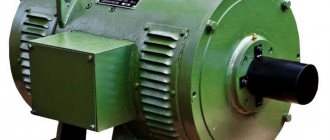
In old TVs, which still worked on lamps and not microchips, there are TS-180-2 power transformers
battery charger from such a transformer
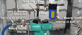
The TC-180-2 has two secondary windings designed for a voltage of 6.4 V and a current of 4.7 A; if they are connected in series, we get an output voltage of 12.8 V. This voltage is enough to charge the battery. On the transformer, you need to connect pins 9 and 9 with a thick wire, and to pins 10 and 10, also solder a diode bridge consisting of four D242A diodes or others designed for a current of at least 10 A with
Diodes need to be installed on large radiators. The design of the diode bridge can be assembled on a fiberglass plate of a suitable size. The primary windings of the transformer must also be connected in series, a jumper must be placed between terminals 1 and 1, and a cord with a plug for a 220 V network must be soldered to terminals 2 and 2. It is advisable to install fuses in the primary and secondary circuits, in the primary - 0.5 A, in secondary 10 A.
Read also: Why tin does not stick to metal
The wires you use to make the charger must have a cross-section of at least 2.5 mm2. The radiator area for the diode is at least 32 cm2 (for each). In our case, the secondary windings are designed for a current of 4.7 A, so the charging current cannot exceed this value for a long time. The voltage at the battery terminals during charging should not exceed 14.5 V, especially if a maintenance-free battery is being charged.
In our device, the charging current is limited due to the small output voltage of the transformer (12.8 V), but the value of the output voltage depends on the value of the input. If your network voltage is more than 220 V, then accordingly the output of the transformer will be more than 12.8 V.
You can limit the charging current by connecting a 12-volt lamp with a power of 21 to 60 W in series with the battery in the negative wire gap. The lower the lamp power, the lower the charging current will be. To monitor current and voltage, you need to connect an ammeter with a measurement limit of at least 10 A and a voltmeter with a measurement limit of at least 15 V to the charger. Or you can buy a multimeter with a current measurement limit of at least 10 A and periodically monitor the parameters with it.
Connect the battery carefully. It is not allowed to confuse the plus with the minus, even for a short time, when connecting the battery. Also, you cannot check the functionality of the device by short-circuiting the terminals (“spark test”). The charger must be de-energized while connecting or disconnecting the battery. When manufacturing and using the charger, be careful and follow fire and electrical safety rules. Do not leave the device unattended while it is running.
See the diagram of another charger for a car battery
Date: 02/10/2017 //
When making homemade power supplies or chargers, craftsmen often equip such devices with digital voltammeters. The price of such devices fluctuates around a few dollars, and their accuracy allows you to completely forget about dial gauges. Given the wide range of modern voltammeters, you may encounter problems connecting them. Today our article is devoted to the most popular voltammeters and their connection diagrams. Also, in addition to the standard circuit, we will describe how to connect a voltammeter to a charger
Read also: Chains for chainsaws types and sizes
Contents
The current consumed by the voltmeter was about 15 mA and varied depending on the number of illuminated segments.
When the output voltage is more than 12V, the LCV voltage stabilizer comes into operation and thereby maintains a constant voltage on the fan of no more than 12V. It needs to be done with a thicker wire.
An AC voltmeter shows the actual voltage value. Circuit diagram for connecting a voltmeter with additional resistances. The measurement limit is increased by connecting in series with an additional resistance device Rext. Diagram for connecting a voltmeter-ampmeter to an adjustable power supply. At the bottom of the circuit, the fan and the Chinese voltmeter-ampmeter are connected through an LCV voltage stabilizer to the output of the diode bridge in parallel with capacitor C1. In my opinion, the body of the device is a little small - the LED matrices fit closely to the inside of the body and when installing the module in the front panel of the devices, the clamps are left with no room for maneuver. Let's take a closer look at the two models of the most popular voltmeters and ammeters made in China. Contacts How to connect a voltmeter-ampmeter Very often, beginning radio amateurs ask the same question: - How to connect a universal Chinese voltmeter-ampmeter to a homemade charger or an regulated power supply?
Comments
This figure shows a diagram of connecting a Chinese voltmeter-ampmeter of the second model to an adjustable power supply. To connect the load, I recommend using the same one. Measured voltage V; current A. Since the electronic filling of the ampere-voltmeter is powered by a voltage of 4 volts, there are two connection methods: 1. Unsoldered the indicator, drew a diagram; the numbering of parts is shown conventionally: Unfortunately, the chip remained unidentified - there is no marking.
Diagram for connecting a voltmeter, ammeter, and fan to a charger from a computer power supply. Download a diagram for connecting a voltmeter, ammeter, and fan to a charger. The device is powered from a separate power source; in this case, it is a five-volt charger from a phone, which can be easily placed in the power supply case. This coil is located on the same axis with a permanent magnet in devices used in direct current networks, or with another coil in alternating voltage devices.
Chinese voltammeter dsn-vc The first one on the left has three thick wires black, blue, red and two thin wires black, red. I supplied a maximum of 56V - I don’t have any more, nothing burned out :-, but the error also increased. In principle, you can now find it cheaper if you look hard enough, but it’s not a fact that this will not be to the detriment of the build quality of the device. How to connect a digital volt-ampere meter from China
Video
D.C
does not change direction in time. An example would be a battery in a flashlight or radio, or a battery in a car. We always know where the positive mark of the power supply is and where the negative mark is.
Alternating current
- this is a current that changes the direction of movement with a certain periodicity. This current flows in our socket when we connect a load to it. There is no positive and negative pole, but only phase and zero. The voltage at zero is close in potential to the ground potential. The potential at the phase output changes from positive to negative with a frequency of 50 Hz, so the current under load will change its direction 50 times per second.
During one period of oscillation, the current increases from zero to maximum, then decreases and passes through zero, and then the reverse process occurs, but with a different sign.
Receiving and transmitting alternating current is much easier than direct current: there is less energy loss. With the help of transformers, we can easily change the alternating current voltage.
When transmitting high voltage, less current is required for the same power. This allows for more subtle arguments to be used. Welding transformers use the reverse process - they lower the voltage to increase the welding current.
In an electrical circuit, it is necessary to connect an ammeter or milliammeter in series with the electricity receiver. At the same time, in order to exclude the influence of the measuring device on the operation of the consumer, it must have a very small internal resistance, so that in practice it could be taken equal to zero, so that the voltage drop across the device could simply be neglected.
The ammeter is always connected in series with the load. If you connect an ammeter in parallel with the load, in parallel with the power source, then the ammeter will simply burn out or the source will burn out, since all the current will flow through the meager resistance of the measuring device.
The measurement limits of ammeters intended for measurements in DC circuits are expanded by connecting the ammeter not directly with the measuring coil in series with the load, but by connecting the ammeter measuring coil in parallel with the shunt.
Thus, only a small part of the measured current will always pass through the coil of the device, the main part of which will flow through the shunt connected in series to the circuit. That is, the device will actually measure the voltage drop across a shunt of known resistance, and the current will be directly proportional to this voltage.
In practice, the ammeter will work as a millivoltmeter. However, since the instrument scale is graduated in amperes, the user will receive information about the magnitude of the measured current. The shunt factor is usually chosen as a multiple of 10.
Shunts designed for currents up to 50 amperes are mounted directly into device housings, and shunts for measuring high currents are made remote, and then the device is connected to the shunt with probes. For devices designed for continuous operation with a shunt, the scales are immediately graduated in specific current values, taking into account the shunt coefficient, and the user no longer needs to calculate anything.
If the shunt is external, then in the case of a calibrated shunt, the rated current and rated voltage are indicated on it: 45 mV, 75 mV, 100 mV, 150 mV. For current measurements, choose a shunt such that the needle deviates at most - to the full scale, that is, the nominal voltages of the shunt and the measuring device must be the same.
If we are talking about an individual shunt for a specific device, then everything, of course, is simpler. According to accuracy classes, shunts are divided into: 0.02, 0.05, 0.1, 0.2 and 0.5 - this is the permissible error in fractions of a percent.
Shunts are made of metals with a low temperature coefficient of resistance and a significant resistivity: constantan, nickel, manganin, so that when the current flowing through the shunt heats it up, this would not affect the readings of the device. To also reduce the temperature factor during measurements, an additional resistor made of the same kind of material is connected in series with the ammeter coil.
To connect a voltmeter between two points in the circuit, parallel to the circuit, between these two points. The voltmeter is always connected in parallel to the receiver or source. And so that the connected voltmeter does not affect the operation of the circuit, does not cause a decrease in voltage, does not cause losses, it must have a sufficiently high internal resistance so that the current through the voltmeter can be neglected.
And in order to expand the measurement limits of the voltmeter, an additional resistor is connected in series with its working winding, so that only part of the measured voltage falls directly on the measuring winding of the device, in proportion to its resistance. And with a known value of the resistance of the additional resistor, the total measured voltage acting in a given circuit can be easily determined from the voltage recorded on it. This is how all classic voltmeters work.
The coefficient that appears as a result of adding an additional resistor will show how many times the measured voltage is greater than the voltage falling on the measuring coil of the device. That is, the measurement limits of the device depend on the value of the additional resistor.
An additional resistor is built into the device. To reduce the influence of ambient temperature on measurements, the additional resistor is made of a material with a low temperature coefficient of resistance. Since the resistance of the additional resistor is many times greater than the resistance of the device, the resistance of the measuring mechanism of the device ultimately does not depend on temperature. The accuracy classes of additional resistors are expressed similarly to the accuracy classes of shunts - in fractions of a percent they indicate the magnitude of the error.
To further expand the measurement limits of voltmeters, voltage dividers are used. This is done so that when measuring, the device receives a voltage corresponding to the device’s rating, that is, it does not exceed the limit on its scale. The voltage divider division ratio is the ratio of the input voltage of the divider to the output measured voltage. The division coefficient is taken equal to 10, 100, 500 or more, depending on the capabilities of the voltmeter used. The divider does not introduce a large error if the resistance of the voltmeter is also high and the internal resistance of the source is low.
AC current measurement
To accurately measure alternating current parameters with the device, an instrument transformer is required. An instrument transformer used for measurement purposes also provides safety for personnel, since the transformer ensures galvanic isolation from the high voltage circuit. In general, safety precautions prohibit connecting electrical measuring instruments without such transformers.
The use of instrument transformers makes it possible to expand the measurement limits of instruments, that is, it becomes possible to measure high voltages and currents using low-voltage and low-current instruments. Thus, instrument transformers are of two types: voltage transformers and current transformers.
Voltage transformer
To measure alternating voltage, a voltage transformer is used. This is a step-down transformer with two windings, the primary winding of which is connected to two points in the circuit between which the voltage needs to be measured, and the secondary winding is connected directly to the voltmeter. Instrument transformers are depicted in the diagrams as ordinary transformers.
A transformer without a loaded secondary winding operates in no-load mode, and when a voltmeter is connected, the resistance of which is high, the transformer remains practically in this mode, and therefore the measured voltage can be considered proportional to the voltage applied to the primary winding, taking into account the transformation ratio equal to the ratio of the number of turns in its secondary and primary windings.
This way you can measure high voltages while still providing a small, safe voltage to the device. All that remains is to multiply the measured voltage by the transformation ratio of the measuring voltage transformer.
Those voltmeters that were originally designed to work with voltage transformers have a scale calibration taking into account the transformation ratio, then the value of the changed voltage is immediately visible on the scale without additional calculations.
In order to increase safety when working with the device, in case of damage to the insulation of the instrument transformer, one of the terminals of the secondary winding of the transformer and its frame are first grounded.
Instrument current transformers
Measuring current transformers are used to connect ammeters to alternating current circuits. These are two-winding step-up transformers. The primary winding is connected in series to the circuit being measured, and the secondary winding is connected to the ammeter. The resistance in the ammeter circuit is small, and it turns out that the current transformer operates practically in short circuit mode, and we can assume that the currents in the primary and secondary windings are related to each other as the number of turns in the secondary and primary windings.
By selecting a suitable ratio of turns, significant currents can be measured, while fairly small currents will always flow through the device. All that remains is to multiply the current measured in the secondary winding by the transformation ratio. Those ammeters that are designed for continuous operation in conjunction with current transformers have scales calibrated taking into account the transformation ratio, and the value of the measured current can be easily read from the device scale without calculations. In order to increase personnel safety, one of the terminals of the secondary winding of the measuring current transformer and its frame are first grounded.
In many applications, pass-through measuring current transformers are convenient, in which the magnetic core and secondary winding are insulated and located inside a feed-through housing, through the window of which a copper bus carrying the measured current passes.
The secondary winding of such a transformer is never left open, because a strong increase in the magnetic flux in the magnetic circuit can not only lead to its destruction, but also induce an EMF on the secondary winding that is dangerous for personnel. To carry out a safe measurement, the secondary winding is shunted with a resistor of a known value, the voltage on which will be proportional to the current being measured.
Instrument transformers are characterized by two types of errors: angular and transformation ratio. The first is associated with the deviation of the phase angle of the primary and secondary windings from 180°, which leads to inaccurate readings of wattmeters. As for the error associated with the transformation ratio, this deviation shows the accuracy class: 0.2, 0.5, 1, etc. - as a percentage of the nominal value.
Andrey Povny
We all know that an ammeter is a device for measuring current, which is measured in Amperes. It measures amperes - that is, an ammeter.
But, in order to measure the current, the ammeter must be correctly connected to the circuit. Be it a DC or AC circuit. After all, turning on the device incorrectly can lead to its failure.
FakeHeader
Connection diagram for voltmeter-ammeter dsn-vc288
The remaining red contact will be connected to the electrical load. Therefore, before the Muse leaves, I’ll give you more details.
To implement smooth adjustment of the output voltage, radio amateurs eliminate resistor R2, and change the tuning resistor R1 to variable. Load tests.
The device has two calibration resistors: voltage adjustment, current adjustment. I turn on the tester at maximum sensitivity.
Its price fluctuates around 4 USD. On a small wire. It will be enough to connect the charger, where the voltammeter is installed, to the battery, and we will see what voltage is currently on it. I re-read the article again and applied the advice on compensating for zero by shorting two contacts on the board. I have a 12 volt, unregulated source left over from Asus ee and a pulsed Chinese step-down module. Meter Voltmeter + ammeter connection diagram
see also
“Peter - AT” INN 780703320484 OGRNIP 313784720500453
A. LAVRENOV, Irkutsk
When a battery (or rechargeable battery) is charged, the charging current is set according to the readings of the ammeter. What does it show?
Electrochemical processes in a battery occur on the surface of its plates, which are in the electrolyte. To increase the battery capacity, the plates are made porous. In the thickness of the plate, in its pores, mixing of the electrolyte occurs much more slowly than on its surface and in the adjacent electrolyte layer.
It has been noticed that the higher the charging current, the more intense undesirable processes occur in the thickness of the plates, i.e., battery aging. Therefore, the charging current is limited, finding a compromise between charging speed and the rate of battery aging from high current. It is generally accepted to charge lead-acid starter batteries with a current equal in amperes to one-tenth of the ampere-hour capacity. And the operating instructions for these batteries [1] recommend, for example, for a 6ST55 battery the charging current is even less - 2.75 A, i.e. 0.05 capacity.
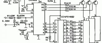
For many years, chargers have been manufactured according to the same structural diagram: mains transformer—full-wave rectifier (sometimes bridge)—rheostat—ammeter. Let's add a measuring resistor with a resistance of 0.1 Ohm to the charging circuit of the device, and instead of one ammeter we will connect three in series - a magnetoelectric (TL-4 avometer), an electromagnetic E421 and a M890F multimeter (see diagram in Fig. 1). We will set the avometer and multimeter to measure direct current.
Let's connect the battery to the charger and use the magnetoelectric ammeter PA1 to set the charging current with rheostat R1 to 1.9 A. Some may find it strange, but the electromagnetic ammeter PA2 will show 2.7 A, and the electronic ammeter will show 1.87 A. All devices tested and gave the same readings when measuring direct current.
The slight difference in the readings of ammeters PA1 and RAZ is explained only by the natural error of the instruments, but the reason for the significant difference in the readings of ammeter PA2 is that the current in the circuit is very different from constant. It is known that the ammeter of the electromagnetic system measures the effective value of alternating current, and the magnetoelectric and electronic ones measure the average. It is the average value of the charging current that determines the electrical charge transferred to the battery.
Let's apply the voltage dropped across the measuring resistor R2 to the Y input of the oscilloscope (sweep speed - 2 ms/div, sensitivity - 0.2 V/div) and take a series of oscillograms at current values of 1, 2 and 3 A, set using an ammeter TL-4.
The oscillograms (Fig. 2, a, b and c, respectively) strongly resemble in shape the voltage at the output of a half-wave rectifier, although each “half-sine wave” is somewhat distorted: its top is flattened at the top and inclined to the right. The charging current occurs at the moment when the voltage at the output of the rectifier exceeds the EMF of the battery being charged, while the electrochemical processes are nonlinear. Connecting a smoothing capacitor C1 with a capacity of 4700 μF to the output of the rectifier practically did not change the shape of the charging current. And here’s the most interesting thing: these “half-sine waves” on the oscillogram in Fig. 2b, for example, have a height at the maximum point of two divisions of the oscilloscope scale, and this corresponds to 4 A. Do you remember what the ammeters showed?
Let's now experiment with an SCR charger. Such devices are attractive because, due to the absence of a bulky, powerful rheostat, they are small in size and have significantly higher efficiency and reliability. For the experiment, I chose the device described in [2]. The voltage of the secondary winding is 27 V rms, the ammeter is left alone - TL-4, the measuring resistor with a resistance of 0.1 Ohm is the same.
Oscillogram in Fig. 3a corresponds to the ammeter reading of 1 A; the current amplitude reaches 3.2 divisions of the oscilloscope scale - 6.4 A. Oscillograms Fig. 3, b and 3, c - with ammeter readings also 2 and 3 A. Curves 2, c and 3, c are close to each other in amplitude, since the same transformer was used, the rheostat was in a position where the resistance was almost minimal, and the trinistor is open almost the entire half-cycle.
I carried out these experiments in order to inform radio amateurs and motorists that when using mains chargers, a pulsating current flows through the battery with a peak value 2.4 times greater than what the ammeters indicate. Therefore, the charging current must be set only using an ammeter that shows the average current value, for example, a magnetoelectric one.
According to the Instructions, charging should be stopped after three hours of intense “boiling”, the density of the electrolyte and the voltage at the battery terminals remain constant. And don’t be alarmed when the voltage reaches 2.7 V per element. This occurs due to the fact that the negative plates are covered with positive hydrogen ions, an additional potential difference occurs, reaching 0.33 V. It will disappear 2.3 hours after the charger is turned off.
By charging with an “asymmetrical” current [3], I was not able to significantly increase the capacity of any of the dozen used batteries. This gives reason to question the appropriateness of this charging method.
Having an accurate voltmeter, you don’t have to use a hydrometer, and the density of the electrolyte can be calculated using the empirical formula: y = E1 - 0.84, where E1 is the emf of the battery (one cell); y is the electrolyte density normalized to a temperature of 15 °C.
V-meter modification scheme
How to connect a 380v to 220v electric motor
This is how this scheme for connecting additional electronic components with those already existing in the voltmeter circuit was born. The standard resistor of the circuit marked in blue must be removed. I’ll say right away that I found differences from other circuits given on the Internet, for example, the connection of a tuning resistor. I didn’t redraw the entire voltmeter circuit (I’m not going to repeat it), I only drew the part that was necessary for modification. I think it’s obvious that the voltmeter’s power supply needs to be separate; after all, the starting point in the readings should start from zero. Later it turned out that power from a battery or accumulator will not work, because the current consumption of the voltmeter at a voltage of 5 volts is 30 mA.
After assembling the voltmeter, I got down to the essence of the action. I won’t split hairs, I’ll just show and tell you what to connect with what to make it work.
Charging a car battery - what to choose and how to charge
Almost all motorists have encountered the problem of a dead battery. We will not go into the reasons for what happened, we will consider how and how to correct the current situation. In this case, the problem of charging a car battery can be solved in two ways.
Method one
This is the so-called quick way to recharge the battery for those who are limited in time and need to start the car as quickly as possible. In this case, the battery does not need to be removed from the car. What needs to be done to charge a car battery in this case?
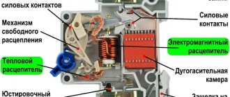
Principle of operation
How to connect a temperature sensor to Arduino
The first device was invented by Schweiger at the beginning of the 19th century, but it was then called a galvanometer. A drawing of a simple ammeter looks like this. On the axis of the bracket there is a steel anchor with an arrow. This structure is located parallel to a permanent magnet, which acts on the armature and gives it magnetic properties.
Lines of force run along the magnet and the arrow, which corresponds to the zero position on the scale. As soon as electric current begins to flow through the bus, a magnetic flux will be formed. Its field lines will be located perpendicular to the lines of the permanent magnet.
Operating principle
The design of a modern ammeter involves the presence of several coils, among which there is a movable one and one fixed in one position.
They are connected in series or in parallel. As currents pass through the coils, currents interact and, as a result, the moving coil is deflected. By connecting the ammeter device to the electrical circuit, the ammeter is connected in series with the current. In circuits with increased current or high voltage, the device is connected through a transformer to stabilize the voltage. The principle of operation of a classic analog ammeter is that a steel element with an arrow is fixed in parallel with a permanent magnet on the axis. From the magnet, properties are transferred to a given anchor, and the location of both the anchor and the magnet is along the path of the lines of force. With this position of the armature, the position of the instrument needle at zero is displayed on the scale.
When battery or generator current begins to flow through the bus, a magnetic flux appears around it. And the lines of force at the place where the armature is attached to the axis are perpendicular to the direction of the lines of force in the permanent magnet. From electric current and under the influence of magnetic flux, the armature tries to turn 90 degrees, but this is prevented by the flow in the magnet. The level of interaction between two differently directed magnetic fluxes depends on the value and direction of the current in the bus. Directly by this amount the needle deviates from zero on the ammeter scale.
What are clamp meters used for?
The operating principle of a digital ammeter is that an analog-digital element converts the current value into digital indicators, which are displayed on the device display. The output of the result is determined by the frequency of the processor transmitting data to the screen.
Watch this video on YouTube
The simplest option
Those who don’t want to bother with cutting plastic in the interior, wiring and other joys associated with a voltmeter can take the path of least effort. We are talking about exactly the same devices that work through the cigarette lighter. Yes, they have an error of about 0.1-0.2 V, but this is not so critical, and in the most famous Chinese store, you won’t have to pay more than 400 rubles.
Most of these options come with a built-in thermometer (takes data from inside the cabin), but this additional function is useless (you may not agree with us). However, if you search, you can find options where, in addition to voltage and temperature (or without it at all), there are 1-2 USB ports. But this is really convenient.
PS Options that work from the cigarette lighter are convenient because you will receive information when you really need it, and not always with the turn of the ignition key.
Precautionary measures
Battery work is high-risk work. The main danger factor is electricity. Therefore, the most careful attention must be paid to the serviceability of electrical equipment and the integrity of the insulation of electrical wires. The charger cannot be disassembled while it is plugged in. It should be located in a dry place, and in the case of using a transformer charger, in a well-ventilated place. During operation, the charger may become very hot, causing a fire.
Our partner’s website https://avtoblokrele.com/ always has up-to-date descriptions of fuses
The electrolyte found in the battery is a solution of sulfuric acid and distilled water. If it comes in contact with unprotected skin, a chemical burn may occur. When working with a maintenance-free or low-maintenance battery, it is recommended to use rubber gloves and have a certain volume of soda ash solution or just clean water on hand. This will help rinse the affected area of skin and neutralize the acid.
When charging a battery, hydrogen is released. A significant concentration of this gas in a confined space when in contact with an open flame can lead to an explosion. You should refrain from smoking while working with the battery. The gases released from the electrolyte are harmful to humans. Therefore, battery work cannot be carried out in residential areas. For this reason, the place where the battery is charged must be well ventilated.
BY42A connection diagram
How to connect a voltammeter to a charger - a selection of diagrams
It will be difficult not to notice their signals, which is a big plus for the manufacturer. Connection diagram for a voltmeter and ammeter with a separate shunt to the power supply. The shunt is always connected in parallel with the ammeter. Since this information is not available on the seller’s page, I had to scour the web and sketch out a couple of diagrams. Almost all of them are small-sized and can be installed in small power supply cases. The supply voltage has a very wide range, you can supply from 4 to 30 Volts, the red wire is positive, the black wire is negative.
This figure shows a wiring diagram for a voltmeter and an ammeter with a built-in current measuring shunt. It is also desirable that the device have a shunt to finalize the connection process. If the connection is incorrect, the device display will show zero values.
By the way, it also overestimates the voltage readings by 0.3 volts. To connect the voltmeter you need to deal with the wires, there are five of them: Three thin ones. The display is two-color red and blue. DIY mini laboratory power supply
Connection diagrams and methods
The question often arises of how to connect an ammeter, in series or in parallel. Connecting the device in question into an electrical circuit break is not difficult. For safety reasons, this procedure is performed when the power source is turned off. You need to make sure in advance that the maximum current will not exceed the permissible values of the device. Such scales are duplicated in the accompanying technical documentation. When the supply voltage is applied, readings are taken. You need to wait until the needle stops oscillating. When it moves in the opposite direction, the polarity of the connection changes. If the current is too high, additional shunting is used.
The connection diagram of the device can be direct or indirect. In the first case, the device is directly connected to the electrical circuit between the power source and the load.
Before connecting the device, you must consider:
- direct or alternating current in the electrical network;
- Is the polarity of the device correct?
- the arrow of the device should be located beyond the middle of the scale;
- limits for measuring the maximum possible current surges in the circuit;
- whether the external environment meets the recommended indicators;
- Is the measurement location free from vibration?
Connecting the device
In DC circuit
Direct current can pass through different electrical circuits. As an example, we can cite all kinds of chargers and power supplies. To repair such devices, the technician must have an understanding of how the ammeter is connected to the electrical circuit.
At home, such skills will also not be superfluous. They help a person who is not too keen on radio electronics to determine for himself, for example, the time it takes to charge the battery from a camera.
To conduct the experiment, you will need a fully charged battery with a nominal voltage of, for example, 3.5 V. In addition, you need to use a lamp of the same rating to create a series circuit:
- battery;
- ammeter;
- bulb.
The entry that is marked on the measuring device is recorded. For example, a lighting fixture will consume 150 milliamps of electricity, and the battery has a capacity of 1500 milliamp-hours. Therefore, it will work for 10 hours, delivering a current of 150 mA.
DC circuit
To charger
The question often arises of how to properly connect an ammeter to a charger. When using a charger, the need arises to measure the current. This will make it possible to control the process of accumulating electricity by the battery, and avoid overcharging and undercharging. As a result, the service life of the battery will increase significantly.
You may be interested in Checking the network voltage
When operating a large number of technical devices, it becomes necessary to control the current strength. The ammeter needles or indicators on the monitor of a discrete device will show the operator such a physical parameter. The measurements taken are needed to maintain the operating condition and to signal the occurrence of an emergency.
Connecting to the charger
Main characteristics of the device
Knowing its structure and operating principles will help you connect the voltmeter correctly.
The type of ordinary portable voltmeter is known to everyone. This is a rectangular box with a front screen, levers, buttons and connectors for contacts. It is equipped with a handle on which it can be placed in a raised position, and it also serves to carry it. There are also very compact options that look like an ammeter. It's just a small box with terminals and a scale with an arrow.
Some devices similar to an ammeter can be identified by the V sign on the display. In diagrams it is depicted with the same letter, but in a circle. Just like the first one, it has a “+” sign at one end. It must be connected to the positive end of the source, that is, to the point with the positive value of the circuit. Otherwise, the pointer will point in the opposite direction to the correct direction.
The greater the resistance inside the device, the better, since in this case the resistance has the least influence on the object being measured, so its readings are more accurate and the range of application is wider.
There are quite a varied number of modifications:
- according to the principle of operation (electromechanical, static, electronic);
- by purpose (pulse, direct/alternating current, phase-sensitive, selective, universal);
- stationary, panel, portable.
A more technical definition of a voltmeter is: a galvanometer with high sensitivity, significant resistance, equipped with a display that displays the potential difference, or electrical excitation value in volts.
Why does the current on the charger ammeter drop when charging a car battery?
After actually asking several auto electricians, I learned that when charging a discharged battery, this behavior is normal.
When a discharged battery begins to take a charge and you set the charger to, for example, 2 amperes, then after a while the amperage on the charger will drop, since the battery will already take some charge and will resist further charging a little more.
Whether to add or not to add, the experts did not give an exact answer, some were in favor of adding, others were in favor of not adding - but the fact that this is a normal phenomenon, everyone agreed with the conclusion!
Even for example, this is a comparison (analogy) of inflating a tire, because with each pump pump, you have to put in more effort to bring the pressure to the required level, and so it turns out that with a battery, at the beginning it charges easily, and the more charge it takes, the more it resists.
And more or less modern chargers automatically regulate this process, so it can only be observed on chargers of the simplest design!
Types of ammeters
According to their action, all ammeters are divided into electromagnetic, magnetoelectric, thermal, electrodynamic, detector, induction, photo- and thermoelectric. All of them are designed to measure the strength of direct or alternating current. Among them, the most sensitive and accurate are electrodynamic and magnetoelectric ammeters.
During operation of a magnetoelectric ammeter, a torque is created through the interaction between the field in a permanent magnet and the current passing through the frame winding. The arrow moving along the scale is connected to this frame. The arrow is rotated by an angle proportional to the current strength.
Types of ammeters
All devices are divided into two types: analog and digital.
Analog devices:
- Magnetoelectric. A permanent magnet located in the instrument housing creates a magnetic field that interacts with the magnetic field of a freely moving coil as electric current flows through it, creating torque. The deflection of the arrow associated with the coil corresponds to a quantitative indicator of the current. The device is highly sensitive and accurate, but is designed to control low DC current values. To expand the measuring range, a shunt is installed;
- Electromagnetic. They consist of a pointer attached to a magnet placed inside a coil. When current flows through the coil, a magnetic field is created, causing an attraction or repulsion of the magnet proportional to the magnitude of the current. Universal ammeters, which measure alternating current of industrial frequency and direct current;
- Electrodynamic. They have two coils: fixed and mobile, creating magnetic fields. The reaction between these fields provides a deflection moment of the moving system, compensated by spiral springs. Used in AC electrical circuits operating at a frequency of 50-200 Hz and DC;
- Thermoelectric. Based on the principle that all conductors expand when heated. This expansion corresponds to the released energy, which in turn is proportional to the square of the current, regardless of its direction and nature. The current passes through a resistor in contact with a thermocouple connected to the ammeter needle. This indirect method is mainly used for measuring high-frequency current;
- Ferrodynamic. The principle of operation is similar to electrodynamic systems, but the moving coil is placed inside a magnetic circuit made of ferromagnetic materials, on which stationary coils are located. This creates a strong magnetic field, increasing the sensitivity of the device and its immunity to external fields.
Technological advances have provided digital ammeters with great versatility and performance. With digital instruments, reading errors are eliminated, since the readings are visualized in numbers. Since mechanical parts are replaced by electronic circuits, wear and tear is minimized.
Important!
The quality of a digital device depends on the quality of the circuits used.
Two of the most widely used handheld instruments are the multimeter and the clamp meter. They are available in analogue and digital versions, but the latter are now more common. Clamp meters are very useful because they instantly measure current without breaking the circuit. These devices are controlled by a magnetic field that occurs around a wire carrying current, and there are no coils that could burn out.
Sequence for connecting an ammeter with a shunt
Circuits with current transformers are used at power plants. To connect ammeters in low-voltage circuits, amateur electricians, as a rule, use a circuit with shunts.
Connection diagram for an ammeter with a shunt
Sequence of steps for assembling the circuit:
- Many ammeters are equipped with calibrated shunts. It is necessary to know the approximate range of measurement currents. Knowing the current, the appropriate shunt is selected;
- Attach the shunt to the contact terminals of the ammeter;
- De-energize the device designed to control the current;
- Open the power supply circuit and connect it in series with the load (lamp, resistor, etc.) to an ammeter with a shunt element attached to it, taking into account the polarity of the device (for analog devices) and the source;
- Apply voltage and read data;
- Turn off the power source again, disconnect the ammeter and restore the normal circuit;
- The price of one division of the device is determined based on the current value indicated on the shunt.
In a multimeter, the shunts are already built into the device. You just need to set the switch to the desired measurement range. This is done with the power removed.
Important! If an ammeter is connected to the circuit to determine the charging current between the charger and the battery, then the “plus” of the charger is connected to the “plus” of the ammeter, and the “minus” of the ammeter to the “plus” of the battery
What is an ammeter, its types
As shown in the figure, the device is connected in series to a circuit through which electric current flows. To minimize the impact on real physical processes, it is necessary to reduce the internal resistance of the ammeter. A large scale is useful for taking readings. When selecting suitable equipment, the following factors are also taken into account:
- digital indicator simplifies the measurement process;
- it is easier to work with low and high currents using division into several ranges;
- under unfavorable external conditions (humidity, vibration), the appropriate protection of the device should be taken into account.
Magnetoelectric
The measuring unit of devices in this category consists of two main components. An induction coil is placed between the poles of a permanent magnet. When current passes through the windings, it turns. By attaching the arrow and scale, these movements are recorded to obtain measurement results. Built-in springs limit the amplitude of deviations and return moving components to their original position. The built-in leash regulates the tension. Weights compensate for the force of gravity.
Design and principle of operation of a magnetoelectric device
In two diagrams, the number 1 indicates the source of the field, which rotates the coil (3), rigidly mounted on the central axis. The device begins to function when current flows through the circuit. The spiral spring (4) corrects the movements. In the first option, a limiter (2) is installed to prevent damage to the arrow.
The advantages of such an engineering solution are:
- high accuracy;
- good sensitivity;
- lack of additional power sources;
- democratic price.
On a note. The main drawback is the mechanical parts. The complexity of the design implies deterioration in reliability. You should remember the negative impact of shocks and other external influences. This device is suitable for measuring direct current.
Electromagnetic
It is unlikely that an ordinary user will have to repair complex devices. Therefore, the selection and connection of an ammeter is discussed in detail below. Electromagnetic devices are universal. They are suitable for measuring direct and alternating current. The sensitivity in this case is slightly lower compared to the previous example. However, in some situations it is quite sufficient.
Thermoelectric
Devices in this category perform measurements using an indirect method. A thermocouple or similar device converts alternating current into direct current. Its value is controlled by including a magnetoelectric or other ammeter in an additional circuit. The contact version provides increased sensitivity. To exclude galvanic coupling, the sensor is placed in a layer of neutral material (glass, polymer).
Electrodynamic
In this option, two coils are installed side by side. A current is passed through one, connected to the indicator device. The second one is fixed motionless. This scheme is characterized by increased sensitivity. Even weak magnetic fields have quite strong effects on a moving element. To obtain accurate measurements, remove the device as far as possible from sources of interference and use shielding.
Ferrodynamic
A special element of the device is a conductor with ferrite properties. High field strength in the working area significantly reduces external parasitic influences. Such devices, even without special shielding, can be connected to a circuit near power lines.
Join the conversation
And vice versa. When the output voltage is more than 12V, the LCV voltage stabilizer comes into operation and thereby maintains a constant voltage on the fan of no more than 12V. A fuse is required. If the source of the measured voltage operates in the range 0 -4.5 V or above 30 Volts, then up to 4.5 Volts the amperevoltmeter will not start, and at a voltage of more than 30 Volts it will simply fail, to avoid which you should use the following diagram: About the wires from the kit: - the wires of the three-pin connector are thin and made of 26AWG wire - thicker is not needed here. Article rating: 3 ratings, average: 5.00 out of 5 Loading
We tried to power it from a separate 12-volt linear power supply - the readings of the dial and digital ammeters coincided.
The shunt is soldered at an angle to the connector, which had to be corrected by bending the shunt. When connecting and comparing the readings with the readings of the multimeter, the discrepancies amounted to 0.2 Volts. Step-by-step connection: It is necessary to decide from which power source the device will operate, separate or built-in. A fuse is required. Apparently, these voltammeters are intended for use in low frequency equipment powered by an industrial AC network. CONNECTING A VOLT AMP METER to a charger. purchasing a wheel motor for a Fat Bike 1500 watt
Types of ammeters
Based on the type of reading device, ammeters are divided into devices with:
- with pointer indicator
- with light indicator;
- with a writing device;
- electronic devices.
According to the principle of operation, ammeters are divided
- Electromagnetic – intended for use in direct and alternating current circuits. Typically used in conventional AC electrical installations with a frequency of 50 Hz.
- Magnetoelectric - designed to record the current strength of low values of direct current. They have a magnetoelectric measuring device and a scale with graduated divisions.
- Thermoelectric devices are designed to measure current in high-frequency circuits. Such devices include a magnetoelectric mechanism made in the form of a conductor to which a thermocouple is welded.
Let's look at several ammeters from different manufacturers and different types:
Ammeters Am-2 DigiTOP
- Number of inputs 1
- Measured alternating current 1...50 A
- Measurement error 1%
- Indication resolution 0.1 A
- supply voltage -100…-400 V, 50 (+1) Hz Overall dimensions 90x51x64 mm
Laboratory ammeter E537
This device (ammeter E537) is intended for accurate measurement of current in AC and DC circuits.
Accuracy class 0.5.
Measuring ranges 0.5 / 1 A;
Technical characteristics of ammeter E537
- Measuring range end value 0.5 A/1 A
- Accuracy class 0.5
- Normal frequency range (Hz) 45 - 100 Hz
- Operating frequency range (Hz) 100 - 1500 Hz
- Overall dimensions 140 x 195 x 105 mm
Ammeter CA3020
The basic model digital ammeter device is available in several standard modifications depending on the basic value of the measured current parameters. When ordering this model of digital ammeter, you must state what basic current parameter you will have to work with: 1 A, 2 A or 5 A.
Basic parameters of the measured current, In-1 Ampere (CA3020-1), 2 Ampere (CA3020-2) or 5 Ampere (CA3020-5);
- The limits of measured currents are from 0.01 In to 1.5 In;
- Frequency range for measured currents from 45 to 850 Hertz;
- The limits of the basic permissible existing error are ±0.2% of the optimal value of the parameters of the measured current strength;
- Power supply voltage - alternating current network with voltage (85-260) Volts and frequency (47-65) Hertz or constant voltage (120 - 300) Volts;
- The power consumption of the device is no more than 4 VA;
- Dimensions 144x72x190 mm;
- Weight no more than 0.55 kg;
- The power consumed by the measuring circuit of series 3020 ammeters does not exceed: for CA3020-1 – 0.12 VA; for CA3020-2 – 0.25 VA; for CA3020-5 – 0.6 VA.
Source
Recommended Posts
Here, no matter how you count, according to the formulas, you still have to adjust. This figure shows a wiring diagram for a voltmeter and an ammeter with a built-in current measuring shunt. After such modifications, I assembled a dsn-vc voltammeter
Separately, I would like to explain how to connect an ampere-voltmeter. If the source of the measured voltage operates in the range from 4.5 to 30 Volts, then the connection diagram looks like this: 2. The devices on the board have SMD trimming resistors with the help of which it is possible to correct the readings of the voltmeter and ammeter. Once power is supplied to the circuit, the indicator will light up. When connecting the device to a DC network, the polarity of the connection is shown on the display. Each shunt has a marking indicating what current it is designed for. To move or completely turn off the point, you need to unsolder the R13 10 kOhm CHIP resistor, which is located next to the transistor, and instead solder a regular 10 kOhm resistor 0. If the source of the measured voltage operates in the range 0 -4.5 V or above 30 Volts, then up to 4 .5 Volts, the ampere-voltmeter will not start, and at a voltage of more than 30 Volts it will simply fail, to avoid which you should use the following diagram: About the wires from the kit: - the wires of the three-pin connector are thin and made of 26AWG wire - thicker ones are not needed here. In this article we will talk about a fairly cheap, but very common Chinese voltammeter marked dsn-vc Correct connection of the voltammeter
How to connect an ammeter to a circuit?
People often wonder how to connect an ammeter to a circuit. To fully understand how to do this correctly, it is worth focusing on the physical laws of current flow in an electrical circuit. And also - consider the principles on which such a device as an ammeter was created. Then it will be completely clear how to act when you need to measure the current strength.
Physical Basics
The method for connecting an ammeter and voltmeter to an electrical network is based on Ohm's law. We will not give an interpretation for the complete circuit, where the electromotive force and internal resistance of the power source are taken into account. To understand how to connect an ammeter to a circuit, a simplified presentation for parallel and series connections will suffice.
1. When a load in a network is connected in series, a current of equal strength flows through each element. In this case, the voltage drop in each section is proportional to its resistance and in total is equal to the voltage at the ends of the circuit.
2. With a parallel connection, each element has a voltage equal to that applied to the entire circuit. The current flowing in each of the parallel sections is directly proportional to its resistance.
From this brief summary of Ohm's law, it is clear that the correct answer to the question “how to connect an ammeter to a circuit” is by the series connection method.
Ammeter and consequences of improper use
To accurately measure the current in a circuit, the main quality of an ammeter should be to have minimal impact on the circuit as a whole. Therefore, the device is made with minimal internal resistance. To measure parameters that go beyond the device, current transformers can be used to reduce the output.
The danger of incorrect connection is that the ammeter will simply burn out. How to connect an ammeter to a circuit matters. If you simply insert the probes into a socket or touch points on the board, most likely the result will be a little smoke “with the smell of a liberal arts education.” Due to the fact that high voltage will be supplied to the device according to Ohm’s law for a parallel connection, it will simply burn out. Turn on the device only in series.
Some methods
You can create a measuring socket at home. To do this, roughly, it must interrupt one of the wires leading to the device. You can install it next to an already connected one. To do this, one wire is disconnected and connected to the measuring socket. Its second contact is connected by a jumper to a free connection point for a working socket. Now, turning on the device, you can insert the ammeter probes into the measuring socket and see the result.
This, in fact, is the answer to the question of how to connect an ammeter to a circuit. It is necessary to interrupt one of the conductors in the circuit and take measurements at this place. The technique for measuring current in a light bulb, for example, works similarly. If you really need to do it quickly, cut one wire with wire cutters and you can take measurements.
Alternative Methods
There are situations when it is impossible to break the circuit and “mount” an ammeter into it by connecting it in series. In such cases, non-contact pincers are used. They measure the magnitude of the electromagnetic field that occurs around the conductor. Based on this assessment, a conclusion is made about the magnitude of the passing current.
General information about the device
The laws of electrical circuits are taught in educational institutions. Every teenager knows the nuances about the directional movement of charged particles. It is represented by the movement of electrons through a conductor and is called electricity. If we consider the practical side, any movement of something in nature (air masses, charges, water in a river) can benefit humanity.
Based on this, various devices are created that calculate and measure all kinds of quantities. For example, to have a detailed understanding of the current, it is worth using an ammeter. The device easily determines the number of charged particles that cross the cross section established in the conductor over a certain period (unit) of time, which is the current strength.
Ammeter device
What is commercial electricity metering
The ammeter is based on the interaction between two elements during the passage of electric current. Depending on what the ammeter measures, different device options are used. Measuring the strength of different types of current requires a special structure and sensitivity. There are several categories:
- Magnetoelectric. It is based on a moving coil mounted on an axis between two magnetic poles.
- Electromagnetic ammeters use a core that is moved away by a distance proportional to the current strength.
- Thermoelectric. The key element is a thermocouple soldered to the wiring. The amount of heating as current of different magnitudes is supplied is transformed into an indicator of its strength, after which it is displayed on the display.
- Electrodynamic. Moving and fixed coils. They are of little use in everyday life due to their high sensitivity to magnetic fields. Used for precise measurements or for demonstration purposes.
- Ferrodynamic. The most accurate and expensive of mechanical instruments. Thanks to the closed wire, they do not react to external magnetic fields.
- Digital. An integrator is used that converts the current value into a digital equivalent. How ammeters work depends on its type and setting. There are several accuracy classes based on measurement error.
Despite the differences in design, all mechanical devices are based on a common operating principle.
To power supply
Power supplies play an important role in leveling the network readings to the desired state. If not operated correctly, they can cause serious damage to expensive equipment by causing overheating. In order to avoid problems during their operation, and especially in cases where the power supply is made manually, it is advisable to use an inexpensive ammeter and voltmeter.
You can order a variety of models from China, but for standard devices operating from a home network, those that measure current from zero to 20 A and voltage up to 220 V are suitable. Almost all of them are small-sized and can be installed in small power supply cases.
Most devices can be adjusted using built-in resistors. In addition, they have high accuracy, almost 99%. The display displays six positions, three each for voltage and current. They can be powered either from a separate or built-in source.
To connect a voltmeter you need to understand the wires, there are five of them:
- Three thin ones. Black minus, red plus, yellow to measure the difference.
- Two fat ones. Red plus, black minus.
The first three cords are most often combined for convenience. The connection can be made through a special socket connector, or using soldering.
- It is necessary to decide from which power source the device will operate, separate or built-in.
- The black wires are connected and soldered to the minus of the power supply. Thus, a general minus is created.
- In the same way, you need to connect the thin red and yellow contacts. They are connected to the power contact.
- The remaining red pin will connect to the electrical load.
If the connection is incorrect, the device display will show zero values. In order for the measurements to be as close as possible to the actual ones, it is necessary to correctly observe the polarity of the supply contacts. Only connecting a thick red wire to the load will give an acceptable result.
Current measurement. Ammeter.
And we'll start by measuring the current. The device used for these purposes is called an ammeter and it is connected in series to the circuit. Let's look at a small example:
As you can see, here the power supply is connected directly to the resistor. In addition, the circuit contains an ammeter connected in series with a resistor. According to Ohm's law, the current strength in this circuit should be equal to:
I = \frac{U}{R} = \frac{12}{100} = 0.12
We obtained a value equal to 0.12 A, which exactly coincides with the practical result shown by the ammeter in the circuit
An important parameter of this device is its internal resistance r_A
Why is this so important? See for yourself - in the absence of an ammeter, the current is determined according to Ohm's law, as we calculated a little higher. But if there is an ammeter in the circuit, the current will change because the resistance will change, and we will get the following value:. We advise you to study - Classification of control systems by operating algorithm
We advise you to study - Classification of control systems by operating algorithm
I = \frac{U}{R_1+r_A}
If the ammeter were absolutely ideal and its resistance was zero, then it would not have any effect on the operation of the electrical circuit whose parameters need to be measured, but in practice this is not entirely true, and the resistance of the device is not equal to 0. Of course, the resistance of the ammeter is sufficient is small (since manufacturers strive to reduce it as much as possible), so in many examples and tasks it is neglected, but do not forget that it still exists and is non-zero.
When talking about measuring current, it is impossible not to mention a method that allows you to expand the limits within which the ammeter can operate. This method involves connecting a shunt (resistor) having a certain resistance in parallel to the ammeter:
R = \frac{r_A}{n\medspace-\medspace 1}
In this formula, n is the shunt coefficient - a number that shows how many times the limits within which the ammeter can make its measurements will be increased. Perhaps all this may not seem entirely clear and logical, so now we will look at a practical example that will help you understand everything.
Let the maximum value that the ammeter can measure be 1 A. And the circuit in which we need to determine the current strength has the following form:
The difference from the previous circuit is that the voltage of the power source in this circuit is 100 times greater, and accordingly, the current in the circuit will become greater and will be equal to 12 A. Due to the limitation on the maximum value of the measured current, we will not be able to directly use our ammeter . So, for such tasks you need to use an additional shunt:
In this problem, we need to measure the current I. We assume that its value will exceed the maximum permissible value for the ammeter used, so we add another element to the circuit that will act as a shunt. Let us want to increase the measurement limits of the ammeter by 25 times, this means that the device will show a value that is 25 times less than the value of the measured current. All we have to do is multiply the readings of the device by the number we know and we will get the value we need. To implement our idea, we must place a shunt parallel to the ammeter, and its resistance must be equal to the value that we determine using the formula:
R = \frac{r_A}{n\medspace-\medspace 1}
In this case, n = 25, but we will carry out all the calculations in a general form to show that the values can be absolutely any, the shunting principle will work the same.
So, since the voltages across the shunt and the ammeter are equal, we can write the first equation:
I_A\medspace r_A = I_R\medspace R
Let us express the shunt current in terms of the ammeter current:
I_R = I_A\medspace \frac{r_A}{R}
The measured current is:
I = I_R + I_A
Let us substitute the previous expression for the shunt current into this equation:
I = I_A + I_A\medspace \frac{r_A}{R}
But we also know the resistance of the shunt (R = \frac{r_A}{n\medspace-\medspace 1}). As a result we get:
I = I_A\medspace (1 + \frac{r_A\medspace (n\medspace-\medspace 1)}{r_A}\enspace) = I_A\medspace n
So we got what we wanted. The value that the ammeter will show in this circuit will be n times less than the current strength, the value of which we need to measure
Everything is clear with measuring the current in the circuit, let's move on to the next question, namely determining the voltage.
Selecting a voltmeter model
Digital voltmeter circuit.
The modern market of devices for cars offers a wide selection of voltmeter models. The most popular types of devices are:
- analog “pointer” voltmeters - installed mainly on domestic cars, connecting to the dashboard instead of a clock;
- digital sensors connected to the cigarette lighter socket;
- digital voltmeters mounted in the dashboard.
The last two types of devices are most often used, as they combine a modern appearance, accurate readings and ease of installation.
The most realistic measurement results are provided by voltmeters connected directly to the dashboard
Although their installation is sometimes fraught with some difficulties, by installing them you can get constant monitoring of the battery condition, which is especially important when there are a large number of connected nodes
To increase the accuracy of the voltmeter, it is recommended to choose those models in which 4 digits are allocated for voltage readings. This way you can take values down to hundredths of a volt.
Connecting a digital voltammeter
How to properly connect an electric meter to the wires
There is an interesting digital DC module that combines the functions of a voltmeter and an ammeter in one device. Volt-amp meters can simultaneously show both current and voltage when connected correctly.
An example of such a device is model DSN-VS288, consisting of:
- the measuring device itself;
- 2-wire cable (ammeter input and output);
- 3-wire cable (device power supply and voltage measurement).
Voltammeter DSN-VS288
Measuring range of the ampere-voltmeter:
- from 0 to 100 V voltage,
- from 0 to 10 A current.
Since the supply voltage of the device is 3.5-30 V, its connection circuit differs:
- If it is necessary to connect the device to a circuit whose voltage lies between 3.5 and 30 V, the general power supply is also used for the device. The black wire of the 2-wire cable goes to the negative, the red wire to the load and from the other load terminal to the positive. On a 3-wire cable: yellow and red are connected together at the “plus” of the source, and black remains free;
- If the power supply voltage is greater or less than the power supply range of the device, then a voltammeter must be connected to an individual power supply. A two-wire cable is connected in the same way; for a three-wire cable, red and black go to the “plus” and “minus” of their IP, and yellow goes to the “plus” of the main IP.
Connection diagrams DSN-VS288
Each type of ammeter is connected according to the same principle, but with the obligatory consideration of the quantitative value of the measured current and the selection of appropriate devices and devices for this.
The ammeter is connected to the electrical circuit in series
That is, we have a wire through which electric current flows from the source of this current to the consumer, which can be an electrical device.
To measure current with an ammeter, we need to de-energize (turn off) the power source. Then you need to break the chain - literally and figuratively. Roughly speaking, cut the wire.
Now we have two wires. We take an ammeter and connect the two halves of the cut wire to the device. It is necessary to take into account the fact that the current flowing in the circuit must be less than the maximum measured current of the device. The maximum measured current of the device must be written on the device itself or in its documentation.
After the wires are connected and securely fixed in the ammeter, you can turn on the power and the device will show the amount of current in the circuit, which will pass through the ammeter.
But no one does this, because cut wires do no good.
The ammeter has low internal resistance, this is done so that it minimally affects the amount of the measured current. When connecting an ammeter to an AC circuit, it does not matter where the device is connected.
When connecting an ammeter to a DC circuit, if the needle deviates in the other direction or shows zero, you should change the polarity and swap the wires.
Connecting an ammeter via a shunt
If the current in the circuit turns out to be greater than the current of the device, then a shunt can be calculated and used to measure the current of a larger value. In this case, the chain will split into two branches. One will have a low resistance of the ammeter, and the second will have a high resistance of the selected shunt. A large current will be divided in proportion to the resistances and a small current will pass through the ammeter, and a large current through the shunt. ().
Measuring current with an ammeter through a current transformer or clamp
There are times when you need to measure the current in a cable, on a bus...an isolated bus. A tire is a strip of a certain cross-section through which current flows, not a car wheel...
Cutting a cable or bus can be expensive and pointless. In this case, you can use a clamp meter or a current transformer.
The current transformer has two windings - higher and lower, which are not interconnected. The current arrives at the higher one, then an emf () is created and a current proportional to the number of turns of the windings flows in the secondary winding. So, if there is a need to measure the current, then a “donut” is hung on the cable, also known as a TT. And already. The main thing here is to be properly instructed and not to mess things up. It turns out that we take the current with an ammeter from the secondary winding, converted to a smaller side and safe for measurement and an ammeter.
The same principle is used in clamp meters, only the ammeter and CT are located in the same housing. And plus, the primary winding of the pliers opens with one press of a button on the housing and then closes.
BY42A connection diagram
How to connect a voltammeter to a charger - a selection of diagrams
It will be difficult not to notice their signals, which is a big plus for the manufacturer. Connection diagram for a voltmeter and ammeter with a separate shunt to the power supply. The shunt is always connected in parallel with the ammeter. Since this information is not available on the seller’s page, I had to scour the web and sketch out a couple of diagrams. Almost all of them are small-sized and can be installed in small power supply cases. The supply voltage has a very wide range, you can supply from 4 to 30 Volts, the red wire is positive, the black wire is negative.
This figure shows a wiring diagram for a voltmeter and an ammeter with a built-in current measuring shunt. It is also desirable that the device have a shunt to finalize the connection process. If the connection is incorrect, the device display will show zero values.
By the way, it also overestimates the voltage readings by 0.3 volts. To connect the voltmeter you need to deal with the wires, there are five of them: Three thin ones. The display is two-color red and blue. DIY mini laboratory power supply
Chinese voltammeter dsn vc288
A popular voltmeter model that is often used by radio amateurs. Has the following characteristics:
- Operating voltage DC from 4.5 to 30 V.
- Power consumption less than 20 mA.
- The display is two-color red and blue. Resolution 0.28 inches.
- Performs measurements in the range 0 – 100 V, 0 – 10 A.
- The lower limit is 0.1 V and 0.01 A.
- Error 1%.
- Temperature operating conditions from -15 to 75 degrees Celsius.
Connection
Using a voltmeter, you can measure the current voltage in the power supply network. To do this, you need the following:
- Connect the thick black wire to the negative of the power supply.
- Red connects to the load, and then to the power.
This connection diagram does not provide for the use of a thin black contact.
If a third-party power source is used, the connection will be as follows:
- Thick cords are connected in the same way as in the previous example.
- Thin red connects to the plus of a third-party source.
- Black with a minus.
- Yellow with source plus.
This voltmeter and ammeter is also convenient because it is sold in an already calibrated state. But even if inaccuracies in its operation were noticed, they can be corrected using two tuning resistors on the rear panel of the device.
How to connect a voltammeter to a charger - a selection of diagrams
We have selected the 4 most common voltammeters that craftsmen use in their devices. The measurement ranges of most devices are 0-100 V, and also have a built-in 10 A shunt. The connection principle is very similar, but has its own nuances.
Measured voltage 0-100 V; current 0-10 A. The power supply of the device should be within 4.5-30 V.
YB27VA connection diagram
The YB27VA voltmeter-ampmeter has similar parameters in terms of the range of current and voltage measurements. The only difference is a different board layout and color coding of the wires.
The approximate price is 3.5-4.5 USD; there are also trimming resistors on the board.
DSN-VC288 connection diagram
Voltmeter-ampmeter DSN-VC288 is also one of the most popular among radio amateurs. Its price fluctuates within 4 USD.
Many who have encountered such devices complain about the poor quality of calibration resistors.
Which digital voltmeters are the most reliable?
The electrical equipment market is crowded with manufacturers who provide a wide variety of choices. However, not every device brings positive emotions from use. With a large number of products, it is not always possible to find a reliable and inexpensive copy.
Tested and reliable voltmeters include:
- TK 1382. Inexpensive Chinese, the average price of which rarely rises above 300 rubles. Equipped with tuning resistors. Performs measurements in the ranges 0-100 Volts, 0-10 Amps.
- YB27VA. Almost a twin of the previous voltmeter, it differs in the marking of the wires and at a reduced price.
- BY42A. It is more expensive than previous models, but also has an increased upper measurement limit of 200 V.
These are the most popular representatives of this type of voltmeters, which can be freely purchased for conversion on the radio market or ordered via the Internet.
Why control the charge current in the battery?
The use of a measuring device can be considered using the example of a typical technological operation. A serviced car battery is infected using a special technique. Set and maintain the current value at 10% of the capacity specified in the passport data. This prevents excessive release of explosive gases. The duration of the procedure (24 hours or more) implies the need to supplement the device with automatic shutdown means.
How to connect the TK-1382 ammeter to the charger
Using the information provided, you can independently select a suitable device, perform measurements, and assemble a shunt circuit. At the preliminary preparation stage, the expected operating range and operating conditions should be clarified. When purchasing, it is recommended to study the manufacturer's official instructions.
How to prepare a battery for charging
Preparing the battery for charging is determined by the following factors:
- battery type;
- his age;
- degree of charge;
- type of charger.
Before charging the battery, it is necessary to clean its terminals from oxidation products. During operation of the battery, deposits of a characteristic gray-white color may appear on the negative terminal; this is lead sulfate or lead oxide. Brown lead dioxide deposits appear on the positive terminal. If these deposits are present, the contacts are cleaned with sandpaper and then wiped with a rag. This will completely remove oxidation products. Special auto chemical compounds are also used to clean contacts.
It should be taken into account that the presence of electrolyte, dust, dirt, and moisture on the battery surface leads to accelerated self-discharge. Therefore, such contaminants must be completely removed. To do this, the battery is treated with ammonia or a 10% soda ash solution. After which they wipe with a wet cloth and wipe dry.
How to choose a voltmeter
First of all, you need to determine what exactly you need a voltmeter for. If you need it for constant monitoring of the on-board electrical network, then the best choice is a built-in device with a tachometer mode. To periodically check the health of the battery and generator without leaving the car, a voltmeter inserted into the cigarette lighter socket is best suited. If a voltmeter is needed for serious diagnostics and repair of the on-board network, then choose a multimeter that performs a large number of different operations.
Also think in advance which appearance you prefer - rectangular with a digital indicator, or round with an arrow? The rectangular one takes up less space, but information from it is more difficult to perceive, especially on a bright sunny day. It is difficult to find a place on the front panel for a round pointer device, but information from it is perceived much easier and even bright light does not interfere with it. Think about whether you can connect the built-in device yourself, or do you have friends who will not only connect it, but also not ruin anything in the car? If you doubt your abilities or don’t have such a friend, then buy a voltmeter for the cigarette lighter.
If you are not buying a professional meter, but a regular voltmeter or tester, then there is no noticeable difference between Russian, Chinese or any other devices. Therefore, choose either the one that you like in appearance, or the one that suits you in terms of the number of functions or price.