The use of an air pneumatic relay allows you to automate the filling of the compressor receiver with compressed gas. The operator of equipment with a pressure switch does not need to monitor the process, trying to fix the limit parameters. As a result, engine damage is prevented. Significant results, right?
If you are planning to purchase a pressure switch for your compressor, then you have come to the right place. Here you will find a vast amount of extremely useful information about the principles of operation of the device, its configuration and connection methods.
We have described in detail the existing types of pneumatic relays. They provided options for connecting to a household and industrial network with extremely clear diagrams. We looked at typical breakdowns and ways to prevent them. The information and useful tips we provide are supplemented with graphic, photo and video applications.
Operating principle of a pressure switch
The name of the relay is determined by its purpose - controlling a piston compressor to maintain the required atmospheric pressure in the receiver. It is rarely found on a screw type device responsible for compressing and supplying air.
I take into account the magnitude of the pressing force in pneumatic automation; the device acts on the voltage line, closing or opening it. Thus, insufficient pressure in the compressor starts the motor, and when the required level is reached, it turns it off.
This standard operating principle, based on connecting a normal closed loop to a circuit, is used to control the motor.
The design of all ejectors contains a cylinder containing air at a certain pressure. Reducing it requires turning on the engine to replenish the supply. If the situation is the opposite and an excess is detected, the supply is stopped so that the container does not burst. These processes are controlled by a pressure switch
Modifications with the opposite operating algorithm are also presented: when reaching minimum values in the compression circuit, the pressure switch turns off the electric motor, and at maximum values it activates. Here the system operates in a normally open loop.
The operating system is made up of spring mechanisms with varying degrees of rigidity, reproducing the response to fluctuations in the air pressure unit.
During operation, the indicators formed as a result of the elastic force of tension or compression of the springs and the pressure of the atmosphere pressed by the device are compared. Any changes automatically activate the action of the spiral and the relay unit connects or disconnects the electricity supply line.
However, it is worth considering that the design of the review model does not provide for regulatory influence. Exceptional impact on the engine. In this case, the user has the opportunity to set a peak value, upon reaching which the spring will fire.
Purpose
After the compressor engine starts, the pressure in the receiver begins to increase.
If the excitation rheostat slider R is moved, then a resistor will be introduced into the SHOV winding circuit. The presence of a free connector allows you to install the control pressure gauge in a place convenient for the user. Control the pressure using the pressure gauge and set the required values.
Other names are telepressostat and pressostat. To do this you will have to: Disconnect the wiring from the contacts; Cut through the motor tubes connecting it to other parts; Image 4 - biting the motor tube Unscrew the mounting bolts and remove from the casing; Disconnect the relay by unscrewing the screws; Image 5 - disconnecting the relay Next, you need to measure the resistance between the contacts; By applying the tester probes to the output contacts, normally you should get OM depending on the model of the engine and refrigerator. The working system consists of springs of different levels of rigidity that respond to changes in pressure.
There may also be other auxiliary mechanisms that require activation: a safety or unloading valve. Types of pressure switch devices There are only two variations in the design of the automatic compressor unit. With the help of a relay, it becomes possible to operate automatically while maintaining the required compression level in the receiver.
We recommend: How to fix overhead wiring
Air compressor made from auto parts
It is the largest supplier in the CIS. Scheme of automated control of an electric compressor The second contact PB1 turns on the signal relay P2 after 15 s; its closed contact can trigger an alarm, but by this time the pump mounted on the compressor manages to create the required pressure in the lubrication system, and the oil pressure switch RDM opens, interrupting alarm circuit. Control circuit for the electric drive of the fire-ballast pump When power is supplied to the circuit, even before the engine starts operating, the electromagnetic time relays RU1, RU2, RU3 acceleration relays are activated. This indicator must be less than the nominal pressure of the air blower.
Typically, the difference value is set to 1 bar. If the relay malfunctions and the compression level in the receiver rises to critical values, then in order to avoid an accident, the safety valve will operate, releasing the air.
Restarting with the KnP button is possible when contact Rв in its circuit is closed, which corresponds to the position of the Rв slider on the right. The operating system is made up of spring mechanisms with varying degrees of rigidity, reproducing the response to fluctuations in the air pressure unit.
If the pressure switch was found to be the source of the malfunction, the professional will insist on replacing the device. In addition, the pressure drop in the system will be significant. Install a control pressure gauge if it is not necessary, then the threaded inlet is also plugged. Compressor cannot gain speed REPAIR bad start FORTE VFL-50
Complete set of compressor automation unit
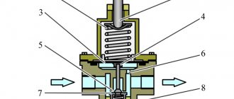
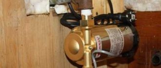
The relay design is a small-sized block equipped with receiving pipes, a sensing element (spring) and a membrane. Mandatory subassemblies include an unloading valve and a mechanical switch.
The pressure switch sensing unit is made up of a spring mechanism, the compression force of which is changed by a screw. According to the factory standardized settings, the elasticity coefficient is set to a pressure in the pneumatic chain of 4-6 at, as reported in the instructions for the device.
Inexpensive models of ejectors are not always equipped with relay automation since such devices are mounted on the receiver. However, during long-term operation, to eliminate the problem of overheating of engine elements, it makes sense to install a pressure switch
The degree of rigidity and flexibility of the spring elements is subject to the temperature of the environment, therefore absolutely all models of industrial devices are designed for stable operation in an environment from -5 to +80 ºC.
The reservoir membrane is connected to the relay switch. During movement, it turns the pressure switch on and off.
The unloading unit is connected to the air supply line, which allows excess pressure to be released into the atmosphere from the piston compartment. This relieves the moving parts of the compressor from excessive force.
The unloading element is located between the ejector check valve and the compression block. If the motor drive stops working, the unloading section is activated, through which excess pressure (up to 2 atm) is released from the piston compartment.
With further start or acceleration of the electric motor, a pressure is created that closes the valve. This prevents overloading of the drive and simplifies starting the device in switched off mode.
There is an unloading system with a time interval of activation. The mechanism remains in the open position when the engine starts for a specified period. This range is enough for the engine to achieve maximum torque.
A mechanical switch is required to start and stop the automatic system options. As a rule, it has two positions: “on.” and "off". The first mode turns on the drive and the compressor operates according to the established automatic principle. The second one prevents accidental starting of the engine, even when the pressure in the pneumatic system is low.
Shut-off valves allow you to avoid emergency situations when elements of the control circuit fail, for example, a breakdown of the piston unit or a sudden stop of the motor
Safety in industrial structures must be at a high level. For these purposes, the compressor regulator is equipped with a safety valve. This ensures system protection in case of incorrect relay operation.
In emergency situations, when the pressure level is higher than the permissible norm, and the telepressostat does not work, the safety unit comes into operation and vents the air. Safety valves in heating systems operate according to a similar scheme, the operating principles and devices of which are described in the article we recommend.
Optionally, a thermal relay can be used as additional protective equipment in the review device. With its help, the strength of the supply current is monitored for timely disconnection from the network when parameters increase.
To avoid burnout of the motor windings, the power is turned off. The nominal values are set using a special control device.
Compressor - device and principle of operation
The name of the device in question comes from “compressio”, which is translated from Latin as “compression”. The main purpose is to compress a gaseous substance in order to move it and use pressure force .
Pressure compressors produced by modern industry are divided into several types and subtypes. Based on the method of gas compression, two large groups of devices are distinguished: volumetric and dynamic. The pressure in them is created by different methods, and accordingly the principle of operation is different.
The design of volumetric models consists of working chambers with a system of valves in which the process of compression and movement of gas is carried out. Schematically, the principle of operation looks like this: the working substance enters the chamber through the inlet valve, which opens only inward and prevents gas from escaping outward. The gas is then compressed by reducing the volume of the chamber and pushed to the outlet valve, which also opens in one direction - outward.
Dynamic designs compress gas by accelerating its movement using a screw system. As a result, the energy of motion is converted into compression force.
On a note! In addition to the principle of operation, compressor devices are divided into groups according to the type of working substance (air, steam, any gas or a mixture of them), the type of drive, the method of heat removal, the industry used, and the final pressure.
Types of pressure switch devices
There are only two variations in the design of the automatic compressor unit. The determination is made based on their operating principle. In the first version, the mechanism turns off the electric motor when the established limits of the air mass pressure level in the pneumatic network are exceeded. These devices are called normally open.
Schematic structure of a membrane pressure switch: 1 – pressure converter; 2 and 3 – contacts; 4 – piston; 5 – spring; 6 – membrane; 7 – threaded connection
Another model with the opposite principle - turns on the engine if a drop in pressure is detected below the permissible level. Devices of this type are called normally closed.
2.5.5. Control systems
All compressors are equipped with some type of monitoring equipment to protect the compressor and prevent unproductive downtime. Sensors are used to determine the current state of the compressor unit. Information coming from the sensors is processed by a control system, which sends a signal, for example, to an actuator. Temperature or pressure sensors often consist of a sensing element and a signal converter. The perceiving element (sensor) determines the measured quantity. The converter converts the sensor output signal into an electrical signal suitable for further processing by the control system.
2.5.5.1. Temperature measurement.
An RTD is usually used to measure temperature. A metal resistor is used as a converter, the resistance of which changes with increasing temperature. The change in resistance is measured and converted into a 4–20 mA signal. The most common resistance thermometer is Pt100. The nominal resistance at 0°C is 100 Ohms. A thermistor is a semiconductor whose resistance changes with temperature. It can be used as a temperature control device, for example in an electric motor. The most commonly used thermistors are positive temperature coefficient (PTC) thermistors. The resistance of a PTC thermistor changes slightly with increasing temperature up to a special point at which the resistance increases abruptly. The thermistor is connected to a controller, which senses this “resistance jump” and issues a signal, for example, to stop the engine.
2.5.5.2. Pressure measurement.
To measure pressure, a pressure-sensing object, such as a membrane, is used. The mechanical signal from the membrane is then converted into an electrical signal of 4-20 mA or 0-5 V. The conversion of a mechanical signal into an electrical signal can occur in various measuring systems. In a capacitive system, pressure is transferred to a membrane. The position of the measuring membrane is sensed by the capacitor plate and converted by the converter into a pressure-proportional constant voltage or direct current. The resistive sensing system consists of a strain gauge connected to a bridge system and attached to a membrane. When the membrane is subjected to pressure, the sensor produces a low voltage signal (mV). It is then amplified to the required level. The piezoelectric system uses special crystals (for example, quartz) that generate electrical charges on their surfaces. The amount of charge is proportional to the force applied to the surface of the crystal (i.e. pressure).
2.5.5.3. Control.
The control instruments are adapted to the specific compressor type, which entails the use of a wide range of instruments. Small piston compressors are equipped only with a conventional safety switch that switches off the motor in case of overload, while large screw compressors have a number of safety switches - converters that react to overload, temperature, pressure, etc. In small, most simple machines, when the protection issues an alarm, the control device turns off the compressor and the machine is blocked from starting again. In some cases, the alarm light may indicate the cause of the alarm. In modern compressors, their compressor performance can be monitored from the control panel, for example, by directly reading pressure, temperature, compressor status, etc. When the transmitter output approaches the alarm limit, the control equipment issues a warning signal. This is done so that action can be taken before the compressor switches off. If the compressor is stopped by an alarm, restarting is blocked until the fault is corrected or the protection is manually reset. Troubleshooting is made much easier with compressors equipped with a memory that records parameters such as temperature, pressure and operating mode. The memory capacity allows you to remember data, for example, for the last 24 hours. Using this data, you can determine the trend over the last 24 hours, and then, using fault finding logic, quickly track the reason for the compressor stopping.
Structure of pneumatic relay symbols
The marking of the air pressure switch indicates the entire optional set of the device, design features, including information about the factory settings for the pressure differential.
Condor's production models offer a wide range of pressure control equipment. The MDR series is aimed at using ejectors of various powers
Let us examine the designations in more detail using the example of devices for air ejectors RDK – (*) (****) – (*)/(*):
- RDK – series of relays for compressors;
- (*) – number of threaded ports: 1 – one port with 1/4”NPT internal thread; 4 – four connectors;
- (****) - type of housing design: T10P - version 10 with a “lever” switch; T10K – “button” switch; T18P – execution 18 with a “switch” switch; T19P - 19 s;
- (*) – factory settings of the threshold response: 1 – 4…6 bar; 2 – 6…8 bar; 3 – 8…10 bar;
- (*) – diameter of the unloading valve: the absence of a symbol means a standardized parameter of 6 mm; 6.5 mm – 6.5 mm.
The difference between the minimum and maximum pressure thresholds is set by the manufacturer and, as a rule, has a value of 2 bar.
However, it is also possible to manually adjust the range of two values – maximum and minimum, but only downward.
The specifics of setting up pressure switches for pumping stations are outlined in the following article, the contents of which we recommend that you familiarize yourself with.
Connection and setup
The general diagram of the compressor installation shows that the pressure switch is located between the unload valve and the secondary control circuit.
Most often, a pressure switch for a compressor has four threaded heads, one of which connects the device to the receiver, and the other connects a pressure gauge to monitor readings. The third can be fitted with a safety valve, and the last has a quarter-inch threaded plug in the thread. With a free connector, the user can install a control pressure gauge at his discretion. The pressure switch is connected according to the following sequence:
- The device is connected to the unloading valve of the receiver.
- Install a control pressure gauge or plug.
- The engine control circuits are connected to the contacts.
- If there are fluctuations in the voltage network, then the connection is made through a surge filter, including when the contact power is greater than that available for the motor load current.
- If there is a need for this, the relay is adjusted through the adjustment screws to the required air pressure.
The connection is accompanied by checking that the voltage in the network matches the factory settings of the pressure switch.
For example, a three-phase network of 380 Volts requires the use of a three-contact group, and for 220 Volts a two-phase group must be used. The adjustment is made when the receiver is at least two-thirds full. The relay is disconnected from the network, the top cover is removed and the compression of the two springs is changed. The operating pressure limit is determined by an adjusting screw with an axis of larger diameter. On the board next to it there is a pressure mark in the form of the letter P and an indication of the direction of rotation of the screw, with the help of which the specified parameter is changed. The second screw helps set the required difference ΔP and has an indicator in which direction it rotates.
To speed up the adjustment process , in some cases the adjusting screw is pulled out, which changes the upper pressure level. Control is carried out according to the readings of the pressure gauge on the pressure regulator for the compressor.
Air relay connection diagrams
The compressor pressure switch is manufactured for connection to electrical circuits of different loads. In accordance with the rating of the power supply line, the appropriate model of the relay unit is selected.
Option #1: to a network with a nominal value of 220 V
If the drive motor is a single-phase device, then a 220 V relay with two groups of contacts is installed.
To work with a single-phase load, manufacturers recommend equipping the unit using models of the RDK series: xT10R-x; xT10K-x; xT19P-x, since these devices have two contact groups
Option #2: to a three-phase network with a voltage of 380 V
For a three-phase load of a 380 V circuit, one of the options can be used: a modification of the relay for 220 V or 380 V, with three contact lines, to simultaneously disconnect all three phases.
Both methods have different schemes. Let's consider the first option:
To operate in a three-phase electrical circuit, a pressure switch RDK-xT18P-x is used. This model is equipped with three contacts and facilitates simultaneous switching of all phases
By choosing the second method, power is supplied from one phase (zero) and in this case the relay rating should be 220 V. For more details, see the following diagram:
It is allowed to use telepressostats of the RDK series: xT10R-x, xT10K-x and xT19P-x with a three-phase load, however, the use of such a circuit requires incomplete disconnection from the supply network. More specifically, one phase will be permanently connected to the load
After connecting to the power supply, you need to understand the additional capabilities provided in the air blocks for ejectors.
2.5.3. Principles of regulation of dynamic compressors
2.5.3.1. Input throttling.
Dynamic compressors allow continuous capacity control through input throttling. The minimum flow is determined by achieving such a degree of pressure increase, which is the surge limit: the operation of the machine becomes unstable. The control range is determined by the design of the machine, such as the number of stages and impeller design, and to a large extent by external factors such as back pressure, intake air temperature and coolant temperature. Typically the minimum flow is between 60% and 85% of the maximum flow.
2.5.3.2. Inlet guide vanes.
The blades are arranged in the form of radial plates at the inlet, causing the incoming gas to swirl, thereby throttling the gas flow. This method works in the same way as throttling, but with a wider control range and improved energy utilization. A typical value for the lower control limit is up to 50–60% of the design flow. It is also possible to increase the capacity and pressure of the compressor to some extent by turning the blades in the opposite direction, but this slightly degrades performance.
2.5.3.3. Blades of the output guide vane (diffuser).
In order to further expand the control range, the flow in the diffuser of the compressor stage can also be controlled. It is usually possible to reduce output by up to 30% while maintaining the desired pressure. Typically, the use of this method is limited to single-stage compressors (due to complexity and increased costs).
2.5.3.4. Pressure release.
To regulate dynamic compressors, an unloader valve was also initially used, which released excess compressed air to the atmosphere. This method is, in principle, no different from releasing pressure in piston compressors.
2.5.3.5. Load - unload - stop.
While throttling of the compressor input is limited by the surge limit, this control method can be implemented in two ways: 1. Throttling. The excess flow is released into the atmosphere (or into the inlet), but with unchanged energy consumption. 2. “Auto Dual” mode. The control system almost completely closes the inlet valve, while the outlet valve opens to the atmosphere (compare with a piston compressor). However, the power consumed in unloading mode is relatively high - over 20% of full load power and depends on the design of the impeller, etc.
2.5.3.6. Speed control.
Speed control is most often used in compressors where flow needs to be controlled and pressure fluctuations are tolerated. When regulation is carried out with constant pressure, it does not provide any advantages compared to other methods of regulation.
Installation of relays and auxiliary elements
In some modifications of pressure switches, you can find additional equipment in the form of flange connections, through which additional equipment is connected. These are basically three-way parts, with a ¼-inch diameter.
By means of several flange connectors, additional elements can be introduced into the system: safety valve, pressure gauge and other necessary mechanisms
To put the device into operation, it must be connected to the receiver. Installation consists of the following steps:
- The device is connected to the compressor through the main outlet.
- A pressure gauge is connected to the device with flanges. There may also be other auxiliary mechanisms that require activation: a safety or unloading valve.
- Channels that are not used for connection must be closed with plugs.
- Next, according to the electrical diagram, the relay is connected to the contacts of the motor control circuit.
Motors with low power can be connected directly; in other cases, additional installation of an electromagnetic starter of appropriate power is required.
Before moving on to setting the threshold response parameters, it is worth paying attention to the operating conditions. First, adjustments are made under pressure. Secondly, the electrical supply to the engine must be cut off.
Types of compressor pressure
Depending on the degree of gas compression and the maximum achieved value of this parameter, there are the following types of devices:
- vacuum devices - used for pumping out air;
- low pressure devices (with an indicator of up to 1.5 MPa) - used in sets of professional pneumatic equipment, household pneumatics and cleaning equipment;
- units of medium compression ratio (over 1.5 MPa to 10 MPa) - used in the mining industries, in industrial refrigeration units, air conditioners, refrigerators, in automated starting systems and devices, as well as other industries;
- installations of a high degree of pressure increase (over 10 to 100 MPa) - such equipment is equipped with automation that regulates the compression ratio and is used in many industries;
- ultra-high pressure devices (from 100 MPa) - used in metallurgy and other large industrial production.
Adjustment and commissioning process
Factory set parameters do not always meet consumer requirements. In most cases, this is due to insufficient compression force at the highest point of disassembly.
The operating range of the pressure switch may also not be suitable. In this case, independent adjustment of the actuator will be relevant.
Standard factory settings: upper limit 2.8 atmospheres, lower limit 1.4 bar. The parameters are monitored visually using a pressure gauge included in the standard pressure switch kit. New models, for example, Italtecnica, have a transparent body and are equipped with a compression scale indicator directly on the relay
To begin setting the operating compression value, you will need to inspect the engraved plate, which indicates the parameters of the electric motor and compressor.
We only need the largest value that the device produces. This indicator indicates the maximum pressure force that can be set on the relay for the correct operation of the entire pneumatic system.
If you set the specified value (in the figure 4.2 atm), then taking into account all factors - differences in power supply, exhaustion of the service life of parts, etc. - the compressor may not reach the maximum pressure, and accordingly it will not turn off.
In this mode, the working elements of the equipment will begin to overheat, then deform and eventually melt.
The maximum ejector value must be taken into account when determining the maximum relay value. This indicator should be less than the rated pressure of the compressor. In this case, all elements of the system will work uninterruptedly
For reliable operation without shutdowns, it is necessary to set the highest shutdown pressure on the relay, which does not reach the nominal value engraved on the compressor, namely 0.4-0.5 atm lower. According to our example - 3.7-3.8 atm.
The pressure limits at which the compressor is turned on/off are regulated by a single bolt. In order not to make a mistake with the choice of direction for increasing/decreasing, arrows are placed on the metal base
Having determined the level that will be set, it is necessary to remove the relay housing. Under it there are two adjusting elements - a small and a large nut (in Figure 1.3).
Nearby there are arrow indicators for the direction in which the twists will be made - thereby compressing and unclenching the spring mechanism (2.4).
A large screw clamp and spring are provided to control compression settings. When twisted clockwise, the spiral compresses - the compressor switch-off pressure increases. Reverse adjustment - weakens, and accordingly, the pressure level for shutdown decreases.
It is worth remembering: by increasing the shutdown compression strength, we are changing the factory settings, which were set taking into account the regulatory requirements for the operation of the equipment. Before making adjustments, check the technical documentation of the device so as not to exceed the limits stated by the manufacturer
When reproducing settings, the receiver must be at least 2/3 full.
Having understood the purpose of the elements, let's proceed:
- To ensure the proper level of safety, we turn off the power supply.
- Changing the compression level of the springs is done by turning the nut several turns in the required direction. On the board, near the large-diameter adjusting screw, according to the standards, there is a symbol in Latin letters P (Pressure), a smaller one - ΔР.
- The adjustment process is monitored visually on a pressure gauge.
For convenience, some manufacturers place the adjusting fittings for changing the nominal value on the surface of the device body.
How to make a relay yourself
A new relay costs from 300 rubles (the price depends on the manufacturer, quality, operating parameters). If you wish, you can make the element yourself. Typically, a working relay removed from a regular household refrigerator is used as a basis. The optimal choice is devices with a reverse firing sequence. The relay turns on as the temperature inside the refrigerator rises, and turns off when the values drop.
You can construct a relay with your own hands according to the following scheme:
- Set the location of the contacts using the chain ring.
- Modify the area where the relay connects to the compressor by connecting the pipe with a pressure gauge to the valve mechanism, and the contacts to the terminal elements inside the engine circuit.
- Find the adjustment screw under the cover. Turn on the compressor, observing the correct sequence of rotations and at the same time monitoring the numbers on the pressure gauge.
- Set to the bottom position, start moving the button rod from the front part.
- Put the cover back and make a blind adjustment.
In order to increase the overall safety of the device during operation, pressure adjustment intervals are set at 1–6 atmospheres. When using devices with reinforced bellows, the limit values increase to 10 atmospheres, and this is sufficient in most cases.
Sources
- https://stankiexpert.ru/tehnologicheskaya-osnastka/zapchasti/rele-davleniya-dlya-kompressora.html
- https://osensorax.ru/davleniye/rele-davleniya-dlya-kompressora
- https://sovet-ingenera.com/elektrika/rele/rele-davleniya-dlya-kompressora.html
- https://Tehno.expert/holodilnik/shema-podklyucheniya-kompressora.html
- https://www.s-compressor.ru/spares-pressure-switches
- https://proinstrumentinfo.ru/rele-davleniya-dlya-kompressora-220-v-380-v-shema-ustrojstvo-nastrojka/
- https://make-a-choice.ru/shema-podklyucheniya-kompressora-holodilnika/
- https://tokar.guru/stanki-i-oborudovanie/kompressory/izgotovlenie-rele-davleniya-vozduha-dlya-kompressora.html
Possible malfunctions of the device
Several malfunctions characteristic of pressure switches are noted. In most cases, they are simply replaced with new devices. However, there are minor problems that you can fix yourself without the help of a repairman.
If the cause of the malfunction was determined to be a pressure switch, the technician will insist on replacing the device. All service actions for cleaning and replacing contacts will cost the user more than purchasing and installing a new device
The most common malfunction is characterized by air leakage from the relay when the receiver is turned on. In this case, the culprit may be the start valve. It is enough to replace the gasket and the problem will be eliminated.
Frequent starting of the compressor indicates loosening and displacement of the adjusting bolts. Here you will need to double-check the threshold for turning on and off the relay and adjust them according to the instructions in the previous section.
2.5.7. Central Administration
Central control of compressors usually involves the use of intelligent control systems. The main requirements for the system are the ability to maintain a given pressure within narrow limits and the most economical operation of the entire installation. To perform these tasks, the system must be able to predict events in the compressor system and at the same time monitor the load on the compressor. The control system perceives the rate of pressure change in the direction of increase or decrease (i.e., the derivative of pressure with respect to time). Using these values, the system can perform calculations that make it possible to predict compressed air consumption and, for example, unload and load or start and stop machines. In properly designed installations, pressure is maintained to within ±0.2 bar. To ensure economical operation, it is essential that the central control system can select the compressor or combination of compressors when compressors with different capacities are combined in the system. Compressors must operate virtually continuously under load in order to minimize idling time and therefore achieve the greatest economy. Another advantage of a comprehensive control system is that older machines can be connected to the system and thus modernize the entire installation in a relatively easy way. Operation becomes more economical and reliability increases.
Troubleshooting methods
A more difficult problem lies ahead if the compressor does not work. There may be several sources. Let's consider one of them - melting of the pressure switch contacts due to erosion arising from electrical sparks.
Burning of the contact group occurs due to electric spark erosion, which is formed as a result of the opening of the contacts. However, it is not always possible to replace elements - some modifications are no longer available for sale
To eliminate this type of malfunction, you can use one of the following methods: clean the surface, which extends the service life by at least 3 months, or repair it by replacing the contacts in the terminal clamps.
Step-by-step instructions for the second option:
- Bleed all air from the receiver and turn off the power to the ejector. Remove the pressure switch.
- Having removed the protective housing, disconnect the wiring connected to the group of contacts.
- Using a screwdriver, you need to remove the terminal with contacts and drill out the burnt lines from it.
- You can replace the wire with copper wire. It is necessary to select it taking into account the diameter of the hole, since it must fit tightly into the seat. It is inserted into the hole and pressed on both sides.
- Similar actions are performed with the remaining burnt lines.
- After the contact group is assembled, it is mounted in its original place and the pressure switch cover is screwed on.
The compressor relay operates in difficult conditions, subject to wear and failure.
Although the repair is not cost-effective, those familiar with the device can perform the repair themselves. However, the option of replacing it with a new device still remains profitable.
Refrigerator compressor connection diagram
How to connect a compressor from a refrigerator without a relay directly
Connection diagram without a relay
First of all, the common terminal is called. Then a terminal is attached to it, the second is connected to the working winding. It is important to use the resistance indicator to determine which one is working. The value should be low, high indicates the starting winding.
You need to know how to connect a compressor from a refrigerator without a relay, otherwise the unit will overheat and fail . You should check the penetration of the housing, otherwise you can feel an electric shock when you touch it with your hand. To check the winding, the left terminal is connected to the output winding, the right terminal is connected to the other side of the housing. Other terminals are also checked. If they are in good working order and do not break through, then the device can be used. This working compressor is reliable and safe. If you do not have sufficient skills and knowledge, it is better to contact a service center, since specialists know exactly how to connect a refrigerator without a relay directly.
Incorrect actions will lead to serious damage.
How to connect a compressor to a refrigerator with a condenser
The procedure for connecting a device compressor with a capacitor begins with connecting the motor to the electrical network using terminal blocks. First, contact is made with the common wire, and then with the working wire. Electricity is supplied to the starting output through a short contact of a bare wire.
The procedure should be carried out with caution to avoid electric shock. After connecting to the network, a hum will be heard from the blower. The motor will start blowing air when it comes into contact with the start output. So it should work for no more than 15 minutes. The case can heat up to 50°. Overheating must not be allowed. The electric motor should start. If this fails, you need to check the components in the power circuit.
Checking the functionality of the connected compressor, starting the engine
The serviceability of the compressor is determined with a multimeter. But before doing this, you need to make sure that the engine housing does not break through. If everything is normal, then the multimeter probes are applied to each contact one by one . If numbers appear on the screen, it means that the winding is faulty; the operability of the compressor can be judged when the “∞” sign is displayed.
To continue checking, remove the casing from the compressor. The wiring is disconnected from the contacts. They bite through the electric motor tubes that connect it and other mechanisms. Tighten the mounting bolts and remove the compressor from the casing. Then they unscrew the screws and measure the resistance between the contacts. To do this, apply tester probes to the output contacts. A resistance of 25 to 35 ohms is considered normal. This depends on the model of the refrigerator and the electric motor. If the reading is lower or higher, the compressor must be replaced. Then check the performance with a pressure gauge .
A hose with an outlet is connected to the discharge fitting, the engine is started and the pressure in the compressor is measured. If it is working properly, the pressure gauge will show 6 atm. The device should be turned off immediately, because the pressure will quickly increase and the mechanism may break. In a compressor that is unsuitable for operation, the pressure gauge will show no higher than 4 atm . It will have to be removed and a new one installed. In order to replace a failed compressor, certain skills are required, as this process is quite complex. It is best to entrust this work to a professional.
If the pressure turns out to be normal, but the device does not turn on, there may be a problem with the start relay. It may happen that after connecting the motor from the refrigerator, it does not turn on. Most often the reason is jamming. You can fix it yourself using a special device with two diodes. It is connected to the motor windings and voltage is applied for a few seconds. Then after half a minute the procedure is repeated. Thanks to wedging, the motor can be rocked.
Not in all cases, it is possible to determine the cause of a refrigerator malfunction by testing the electrical circuits of the compressor. To start the electric motor when using inverter devices, you will need an electronic unit installed inside the device. If you try to force such a motor to start, a short circuit may occur, and then it will completely fail. In these cases, it is more correct to seek help from specialized service centers , where experienced professionals work and have the appropriate equipment.
Preparing for work - first start-up of an air piston compressor
Instructions - always start with this. Even if you have extensive experience in handling compressor equipment, information about a specific model will not be superfluous. Beginners will benefit from a visual guide to the main processes, as implemented in the FUBAG instructions, and experienced users will benefit from recommendations on maintenance, selection of oil for a piston compressor, and operating nuances.
Let's move on to preparing the device:
1. If you have transport wheels, start by installing them after unpacking.
2. Check the oil level using a dipstick or eyelet.
3. There is not enough oil - add more. Enough - skip the point and move on to the next one.
4. Now you need to install the compressor correctly. Make sure that it stands on a flat surface to prevent uneven lubrication of the working elements. Will you be working indoors? Then it is worth maintaining a distance of half a meter from the device for free air flow to the compressor engine.
5. Install the air filter.
6. Install the breather (this is where the instructions for your compressor come in handy). 7. That's it, the device is ready for use.
Where would we be without precautions? Do you have to work outside? Then be sure to take care of protection from moisture
So, the device is assembled, you can connect it to the mains and start:
1. Turn the pressure switch to the OFF position. 2. Check and close the air valve. 3. Connect power supply. 4. Turn the pressure switch to the RUN position.
The compressor will start working and maintain pressure, alternately reaching the upper and lower limits. The actual value is shown on the pressure gauge. To disable the automatic mode of alternating start and pause, simply turn off the pressure switch.
Conclusions and useful video on the topic
Details about the design of the pressure switch, as well as a visual process for adjusting its parameters in the plot:
It is also possible to independently assemble the control unit for the compressor; see this video:
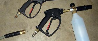
Pneumatic devices are considered safer and easier to use than electric or gasoline models. There is a wide selection of additional equipment that works with compressed air: guns for washing, inflating tires or painting and many others.
With the help of a relay, it becomes possible to operate automatically while maintaining the required compression level in the receiver.
Please write comments in the block form located under the article test. Share your own experience in operating a compressor with a pressure switch, ask questions, post photos on the topic. It is possible that your recommendations will be useful to site visitors.
2.5.8. Remote control
In some compressor installations it may be necessary to remotely monitor the compressor and control its operation. In small installations it is very easy to connect alarms, operating parameters indication, etc. to the compressor. Typically, remote start and stop can also be arranged. As for large installations, where high costs are involved, the installation of centralized control will require justification. The monitoring system must consist of equipment that provides a continuous overview of the system and also allows access to individual machines to monitor parameters such as intercooler pressure, oil temperature, etc. The monitoring system must also contain a memory that will allow the recording of events that have occurred over the past 24 hours. Registration provides the basis for creating measurement curves and makes it possible to determine whether there is a tendency for parameters to deviate from the specified values. These curves provide the basis for continuous operation or planned shutdown. The system often provides reports on the status of the compressor unit: this can be a general overview or a detailed description of the condition of individual machines.