DC electric motors, now widely used in everyday life and in production, have many advantages, but are characterized by high starting currents. There are several common options for connecting such electric motors.
Thanks to the excellent traction capabilities of DC electric motors, electrical equipment assembled on their basis has become widespread, both in everyday life and in production. Such motors can often be found in modern children's toys, fans, power tools and autonomous industrial electrical installations. They are an integral part of vehicle control and electrification systems. Batteries or rechargeable batteries of different capacities are usually used as a power source.
The DC motor also has many other advantages, including:
- simple speed adjustment;
- possibility of soft start and smooth increase in speed;
- the ability to accelerate to speeds of over three thousand revolutions per minute.
Despite all these advantages, a DC electric motor has a more complex design than an asynchronous AC power unit of 380 or 220 volts, which implies some difficulties in its operation. In addition, there is a danger of significant inrush currents, so there are different ways to connect DC motors, each of which has its own characteristics and nuances. To better understand them, let's take a closer look at the design, operating principle and connection of a DC motor.
DC motor connection diagram
If we try to show the structure of a DC electric motor schematically, we will get an image with two cylinders placed one inside the other. The larger of the cylinders is hollow and motionless and is called a stator or frame. An anchor is placed inside the frame - the smaller of the cylinders, which is movable. In this case, there must be an air space inside between the cylinders and they should not be in close contact. This is necessary because it is in the air gap that the magnetic field is formed.
Three-phase and single-phase motors
For safety, it is better to limit it to Volts. The shaft does not respond to the field due to inertia.
It seems to make it possible to use it where commutator motors fail.
It is shifted 90 degrees relative to the working winding. The coils are absolutely identical, the same. When switched on by a triangle, the motor develops not only more power, but also large starting currents. To start an electrical machine of this type, a starting resistor can be used.
The shaft rotation speed is controlled by the amplitude of the supply voltage. Very often, a combination of a push-button or relay starter, as well as a constantly switched on operating capacitor, is used.
When connected single-phase, it announces the third output. The following are defects that indicate possible problems with the engine, which could be caused by improper operation or overload: Broken support or mounting slots. Schemes for connecting an electric motor are shown in the figure. Connecting a single-phase motor.
DC motor design
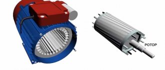
Any electric motor consists of two main parts: the frame (stator) and the armature. On the inner surface of the stator there are poles, which are made of thin sheets of electrical steel, insulated from each other using varnish and ending in extensions - tips. These tips are designed to evenly distribute magnetic induction in the air gap. Several excitation windings are located directly at the poles themselves. Moreover, some of the windings are made with a large number of turns of thin wire, while others are designed with a small number of turns of thick wire.
The armature is a gear cylinder that is mounted on a shaft inside the stator and consists of packages of thin sheets of electrical steel insulated from each other. It is worth noting that between each individual package there are special channels designed for ventilation. At the same time, the individual grooves of the armature are connected to each other by conductors made of copper. Also a necessary condition for the manufacture of an armature is the presence of a two-layer winding.
Types of engines and their design
AC electric motors have a different design, thanks to which it is possible to create machines with the same rotor speed relative to the stator magnetic field, and machines where the rotor “lags behind” the rotating field. According to this principle, these motors are divided into corresponding types: synchronous and asynchronous.
Asynchronous
The design of an asynchronous electric motor is based on a couple of important functional parts:
- The stator is a cylindrical block made of steel sheets with grooves for laying conductive windings, the axes of which are located at an angle of 120˚ relative to each other. The poles of the windings go to the terminal box, where they are connected in different ways, depending on the required operating parameters of the electric motor.
- Rotor. In the design of asynchronous electric motors, two types of rotors are used:
- Short-circuited. So called because it is made from several aluminum or copper rods short-circuited using end rings. This design, which is a current-carrying rotor winding, is called a “squirrel cage” in electromechanics.
- Phase. On rotors of this type, a three-phase winding is installed, similar to the stator winding. Most often, the ends of its conductors go to the terminal pad, where they are connected in a star, and the free ends are connected to slip rings. The phase rotor allows you to use brushes to add an additional resistor to the winding circuit, which allows you to change the resistance to reduce inrush currents.
In addition to the described key elements of an asynchronous electric motor, its design also includes a fan for cooling the windings, a terminal box and a shaft that transmits the generated rotation to the working mechanisms of the equipment whose operation is provided by this motor.
The operation of asynchronous electric motors is based on the law of electromagnetic induction, which states that electromotive force can only arise under conditions of a difference in the speed of rotation of the rotor and the magnetic field of the stator. Thus, if these speeds were equal, the EMF could not appear, but the influence on the shaft of such “braking” factors as load and bearing friction always creates conditions sufficient for operation.
Synchronous
The design of synchronous AC electric motors is somewhat different from the design of asynchronous analogues. In these machines, the rotor rotates around its axis at a speed equal to the rotation speed of the stator's magnetic field. The rotor or armature of these devices is also equipped with windings, which are connected at one end to each other and at the other to a rotating collector. The contact pads on the commutator are mounted in such a way that at a certain point in time it is possible to supply power through the graphite brushes to only two opposite contacts.
Operating principle of synchronous electric motors:
- When the magnetic flux in the stator winding interacts with the rotor current, a torque arises.
- The direction of movement of the magnetic flux changes simultaneously with the direction of the alternating current, due to which the rotation of the output shaft is maintained in one direction.
- The desired rotation speed is adjusted by adjusting the input voltage. Most often, in high-speed equipment, such as rotary hammers and vacuum cleaners, this function is performed by a rheostat.
The most common reasons for failure of synchronous electric motors are:
- wear of the graphite brushes or weakening of the pressure spring;
- wear of shaft bearings;
- collector contamination (clean with sandpaper or alcohol).
Three Phase Alternator
Operating principle of a DC motor
The operating principle of any modern DC electric motor is based on the principle of magnetic induction, as well as the “Left Hand Rule”. If current is passed through the upper part of the armature winding in one direction, and through the lower part in the other, it will begin to rotate. This is due to the fact that, according to the left-hand rule, the conductors that are laid directly in the grooves of the armature will be pushed out of the magnetic field that is created by the frame.
Thus, the upper part will be pushed to the left, and the lower part to the right, which will lead to rotation of the armature itself, since all the energy from the conductors will be transferred to it. However, at the moment when the conductors rotate and parts of the armature change locations, its rotation will stop. To prevent this from happening, the electric motor uses a commutator designed to switch the armature winding.
Classic connection options
Most emails Motors for modern electric drives operate from an alternating three-phase line (each of the three phases is supplied by a separate conductor). Accordingly, the terminal box contains the terminals (input and output) of three windings. They can be connected to each other and to the network using two classic schemes: “star” and “triangle”.
Star and Delta connection diagram
For the first, a characteristic feature is the closure of the end terminals of each coil to one point (in practice, this is one neutral). Meanwhile, the mains voltage is supplied to the input pins. This scheme is characterized by a softer ride, but unfortunately, it does not allow you to develop full power.
The second option with a triangle is characterized by a serial connection of the terminals of the windings: the end of the first is connected to the beginning of the second, etc. This starting option guarantees achievement of the rated power, but during switching on, large currents may arise that can thermally damage the winding terminals.
If you remove the terminal box cover, both connection options will look like this:
Electric motor design and connection
It is an asynchronous electric motor, the stationary component of which has one working winding, connected to a single-phase alternating current source. We call the windings.
Volt connection Unlike a three-phase motor, a two-phase motor is initially designed to be connected to a single-phase network. We call the windings.
The third denomination occupies an intermediate position. The following are defects that indicate possible problems with the engine, which could be caused by improper operation or overload: Broken support or mounting slots.
A longer time under load can lead to overheating, insulation fire and mechanism failure. As is known from the same school physics, a coil with current creates a magnetic field. Active resistors, inductors and capacitors can be used for this. These pumps are used as dosing pumps in food production.
Read additionally: Switch 2 x key hidden wiring
Connecting an asynchronous motor
The latter is proportional to the magnitude of the current, and the polarity depends on the direction of the current in the coil. After gaining speed, the start button is released, the KM1 starter is turned off, turning off Cadditional. This is especially important when powering centrifugal electric pumps that have a strictly defined direction of rotation of the impeller. How to connect a float switch to a three-phase pump From everything described above, it becomes clear that to control a three-phase pump motor in automatic mode using a float switch, you CANNOT simply break one phase, as is done with single-phase motors in a single-phase network. But a vector is equal to the sum of its projections.
Volt connection Unlike a three-phase motor, a two-phase motor is initially designed to be connected to a single-phase network. Methods for connecting electric motors Methods for connecting electric motors First, let's look at the difference between devices and volts. With a power reaching more than 3 watts, it is not recommended to connect the motor, as this may cause a short circuit and damage the RCD.
CONNECTING A THREE-PHASE MOTOR TO A SINGLE-PHASE NETWORK
We will definitely answer you. This connection diagram for a single-phase electric motor with a capacitor has optimal starting properties.
If the engine does not have special starting mechanisms, then at start the resulting torque will be zero, which means the engine will not rotate. The rotor rotates in the static stator winding. To do this, we connect any two in series and apply alternating voltage to them. Connecting a commutator motor Such electric motors are used in almost all household electrical appliances. Connecting a 220V electric motor with a triangle and a star. Demonstration of work. Which type is better?
Connection methods
The rotor will begin to catch up with the stator field.
Instead of a fan cover, a forced cooling fan is installed, see. The thermal relay turns off both phases of the winding if they heat up above the permissible level. This happens automatically - without user intervention.
It indicates the model, type, connection diagram, voltage, as well as other parameters. To turn on a three-phase electric motor, you need to simultaneously apply voltage to all 3 phases.
You have to use some clever promotion techniques. If after this the engine turns out to be hot, then: The bearings may be dirty, jammed, or simply worn out. Three phases are connected to opposite ends of the windings.
Therefore, a single-phase electric motor will not start on its own when connected to the network. Used for adjustable electric drives with high quality performance indicators, such as readiness to restart and rotational uniformity.
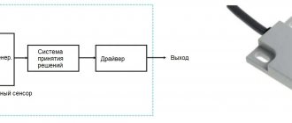
Operating principle and startup scheme
Essentially, you have a neutral and a phase in the outlet. The capacitor contact should be connected to zero, while the other should be connected to the next output of the motor. The shadow that the arrow casts on the wall varies as a sine with a period of 1 minute, and the shadow cast on the floor changes as a cosine. The motor is connected to the network through an electromagnetic starter.
They can be found in washing machines, coffee grinders, meat grinders, screwdrivers, heaters and other appliances. Is it true that a three-phase motor is simpler? Instead of a fan cover, a forced cooling fan is installed, see
With a capacitor on the start winding. For example, if the current is 1. Typically, the working winding of asynchronous motors has a resistance of no more than 13 Ohms. How to connect a magnetic starter. Connection diagram.