Design and advantages of carbide inserts
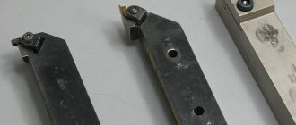
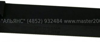
The design of carbide inserts depends on the mounting method and cutter configuration. When bolted, the plates have a hole for the fastener. Depending on the type of tool, carbide inserts for turning tools can be square, rhombic, triangular, pentagonal, etc. The number of cutting edges and service life depend on the number of edges.
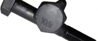
Carbide inserts are made by pressing and heat treating powders of tungsten carbide, titanium carbide and other high-strength materials. In addition to hardness, the plates have high wear and heat resistance and are able to retain their properties at temperatures up to +1150°C.
Main operational advantages:
- The ability to use on one cutter the most suitable carbide insert, the type of which is most suitable for the workpiece material. This allows you to have a removable set for various operations.
- Replacing a worn and damaged insert will cost much less than replacing a solid cutter. The use of removable plates is justified for small- and medium-scale production, as well as for frequent changes in the product range.
- Minimum plate replacement time.
- High reliability even under intensive work conditions.
- Unification of plates for easy replacement and selection for the type of processing and steel grade.
Wiper plate geometry
“Better, higher quality, faster and more...”
We have all been convinced more than once that in modern realities this is how the task is posed. Manufacturers of metal-cutting tools are trying in every possible way to help us achieve our goal. One of the technologies that improves the quality of the machined surface and increases the processing speed is Wiper technology.
Wiper is an insert geometry with a wiper cutting edge for high feed applications.
Let's look at the nose radius of a regular insert compared to the nose radius of a Wiper insert, it looks like this:
As you can see, this technology has a number of technical features, namely:
- Each Wiper cutting edge has a combination of several radii at its apex (about 3-9)
- The total length of the cutting edge of the Wiper insert is longer compared to a conventional insert
- Increased cutting edge length improves surface quality
- Longer contact lengths increase cutting forces, making the Wiper insert more sensitive to vibration when machining soft parts.
From this we can highlight the following advantages of this technology:
- Smooth chip removal and reduced cutting force thanks to deep chipbreaker profile.
- Provides sharpness and strength of the cutting edge.
- The multi-radius chipbreaker design reduces cutting vibration, increases cutting range and provides better surface quality, which is especially important in finishing operations.
Wiper plate Regular plate
Now we need to consider the quality of the machined surface when using inserts with Wiper technology
When turning, the cleanliness of the machined surface depends on many factors. In particular, on the ratio of the apex radius and feed. Theoretically, the maximum micro-roughness height is calculated using an approximate formula and is used for comparison with the surface roughness requirements for a given operation and for the first feed selection.
Rt = (fn2/ 8*RE)*1000 where
Rt = Maximum profile height
fn = Feed value
RE = Corner radius
Ra = Arithmetic mean profile height
From all of the above, we see that machining with a Wiper insert with double feed provides the same surface quality as when machining with conventional inserts with normal feed. And machining with a Wiper insert with normal feed provides twice the surface quality compared to machining with conventional inserts. Schematically it looks like this:
Regular plate
Wiper plate - double feed, same Ra value
Wiper insert - same feed, half the Ra value
Let's summarize
The Wiper chipbreaker has a wide range of applications. Inserts using this technology are available in different alloys and shapes, which makes them suitable for turning a wide range of materials and different types of processing (from finishing finishing to roughing). The use of plates with Wiper technology, due to its features, greatly simplifies our life, allowing us to solve sometimes unsolvable problems.
Used Books:
1) High-performance metal cutting. Textbook SANDVIK COROMANT 2003 Vinogradov D. V.
2) Chipbreakers. Taegutec catalogue.
3) Recommendations for assigning cutting modes and choosing a tool. 2010 M.A. Bolotov, A.N. Zhidyaev, N.D. Pronichev, A.I. Khaimovich
Catalog of carbide tools at the Enex online exhibition: https://enex.market/catalog/Raskhodnye_materialy/metallorezhushchiy_instrument/tverdosplavnyy_instru….
Classification of carbide inserts
For carbide inserts used in modern production, the classification is based on several characteristics. First of all, this is the method of fastening the tool - soldering or mechanical fastening. The second method provides quick replacement and the ability to reuse the plates. When soldering, you can turn over the worn part of the plate or use disposable polyhedral elements.
The inserts also differ in the type of alloy, which determines their characteristics and scope of application. For roughing, VK8 alloy tooling is often used. This material is designed to work with structural steels, gray cast iron and various alloys that are difficult to process. Elements made from T15K6 alloy are more often used for semi-finishing or finishing machining of alloy and carbon steels.
According to their shape, the plates are divided into:
- Round.
- Square.
- Rhombic.
- In the shape of a parallelogram.
- Triangular.
- Pentagonal.
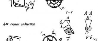
GOST 25395-90 Brazed carbide plates types 01, 02, 61, 62. Design and dimensions
INTERSTATE STANDARD
| BRAZED CARBIDE PLATES TYPES 01, 02, 61, 62 Design and dimensions Hard metal brazed tips, types 01, 02, 61, 62. Design and dimensions | GOST 25395-90 |
Date of introduction 07/01/93
1. This standard applies to inserts for passing, boring and turret cutters.
2. The design and dimensions of the plate must correspond to those indicated in the drawing and table. 1.
* Dimensions for molds.
Table 1
Dimensions in mm
| Designation of performance plates | l | b | s | a, deg. | Main Application | Additional uses | Application by special order | |
| 1 | 2 | |||||||
| 01291 | — | 5 | 3 | 2,0 | — | № 1, № 7 | № 8, № 11 | № 2, № 3, № 4, № 5, № 6, № 9, № 10 |
| 01311 | — | 6 | 4 | 2,5 | — | № 1, № 7 | № 8, № 11 | № 2, № 3, № 4, № 5, № 6, № 9, № 10 |
| 01331 | — | 8 | 5 | 3,0 | — | № 1, № 7 | № 2, № 8, № 11 | № 3, № 4, № 5, № 6, № 9, № 10 |
| 02611 | — | 10 | 6 | 2,5 | — | № 1, № 7 | № 2, № 3, № 8, № 11 | № 4, № 5, № 6, № 9, № 10 |
| 01351 | 01352 | 10 | 4,0 | 18 | № 1, № 2, № 5, № 7 | № 3, № 8, № 9, № 11 | № 4, № 6, № 10 | |
| 61351 | 61352 | 8 | № 1, № 2, № 7 | № 3, № 5, № 8, № 9, № 11 | № 4, № 6, № 10 | |||
| 02631 | — | 12 | 8 | 3,0 | — | № 1, № 2, № 3, № 7 | № 5, № 8, № 9, № 10, № 11 | № 4, № 6 |
| 01371 | 01372 | 5,0 | 18 | № 1, № 2, № 3, № 7, № 9 | № 5, № 8, № 10, № 11 | № 4, № 6 | ||
| 61371 | 61372 | 8 | № 1, № 2, № 3, № 7, № 9 | № 4, № 5, № 8, № 10, № 11 | № 6 | |||
| 02051 | 02052 | 10 | 4,0 | 18 | № 7 | № 1, № 2, № 3, № 5, № 8, № 9, № 10, № 11 | № 4, № 6 | |
| 02691 | 02692 | 14 | № 9, № 10 | № 1, № 2, № 3, № 4, № 5, № 6, № 7, № 8, № 11 | ||||
| 02231 | 02232 | 12 | 4,5 | № 7 | № 1, № 2, № 3, № 5, № 8, № 9, № 10, № 11 | № 4, № 6 | ||
| 02251 | 02252 | 6,0 | № 1, № 2, № 3, № 5, № 7, № 9, № 10 | № 8, № 11 | № 4, № 6 | |||
| 62251 | 62252 | 8 | № 1, № 2, № 3, № 7, № 9, № 10 | № 4, № 5, № 8, № 11 | № 6 | |||
| 02651 | — | 16 | 10 | 4,0 | 18 | № 1, № 2, № 3, № 7, № 9, № 11 | № 5, № 8, № 11 | № 4, № 6 |
| 01391 | 01392 | 6,0 | № 1, № 2, № 3, № 7, № 9, № 10 | № 5, № 8, № 11 | № 4, № 6 | |||
| 61391 | 61392 | 8 | № 1, № 2, № 3, № 7, № 9, № 10 | № 4, № 5, № 8, № 11 | № 6 | |||
| 02271 | 02272 | 18 | 16 | 18 | № 2, № 3, № 5, № 9, № 10 | № 1, № 4, № 7, № 8, № 11 | № 6 | |
| 62271 | 62272 | 8 | № 2, № 3, № 9, № 10 | № 1, № 4, № 5, № 7, № 8, № 11 | № 6 | |||
| 02291 | 02292 | 8,0 | 18 | № 2, № 3, № 4, № 5, № 8, № 9, № 10, № 11 | № 1, № 6, № 7 | |||
| 02671 | — | 20 | 12 | 5,0 | 18 | № 2, № 3, № 4, № 9, № 10 | № 5, № 8, № 11 | № 1, № 6, № 7 |
| 01151 | 01152 | 7,0 | № 2, № 3, № 4, № 5, № 9, № 10 | № 7, № 8, № 11 | № 1, № 6 | |||
| 61151 | 61152 | 8 | № 2, № 3, № 4, № 9, № 10 | № 7, № 8, № 11 | № 1, № 6, № 7 | |||
| 02411 | 02412 | 16 | 6,0 | 18 | № 2, № 3, № 4, № 5, № 8, № 9 № 10, № 11 | № 1, № 6, № 7 | ||
| 02311 | 02312 | 22 | 18 | 7,0 | № 2, № 3, № 4, № 5, № 9, № 10 | № 8, № 11 | № 1, № 6, № 7 | |
| 62311 | 62312 | 8 | № 2, № 3, № 4, № 9, № 10 | № 5, № 8, № 11 | № 1, № 6, № 7 | |||
| 01411 | 01412 | 25 | 14 | 8,0 | 18 | № 2, № 3, № 4, № 5, № 9, № 10 | № 7, № 8, № 11 | № 1, № 6 |
| 61411 | 61412 | 8 | № 2, № 3, № 4, № 9, № 10 | № 5, № 8, № 11 | № 1, № 6, № 7 | |||
| 02431 | 02432 | 18 | 7,0 | 18 | № 2, № 3, № 4, № 8, № 9, № 10, № 11 | № 1, № 5, № 6, № 7 | ||
| 02351 | 02352 | 20 | 10,0 | № 2, № 3, № 4, № 9, № 10 | № 5, № 11 | № 1, № 6, № 7, № 8 | ||
| 62351 | 62352 | 8 | № 2, № 3, № 4, № 9, № 10 | № 5, № 11 | № 1, № 6, № 7, № 8 | |||
| 02451 | 02452 | 32 | 16 | 8,0 | 18 | № 2, № 3, № 4, № 5, № 9, № 10, № 11 | № 1, № 6, № 7, № 8 | |
| 62451 | 62452 | 8 | № 2, № 3, № 4, № 5, № 9, № 10, № 11 | № 1, № 6, № 7, № 8 | ||||
| 01431 | 01432 | 32 | 18 | 10,0 | 18 | № 3. № 4, № 5, № 9, № 10 | № 2, № 7, № 8, № 11 | № 1, № 6 |
| 61431 | 61432 | 8 | № 3, № 4, № 9, № 10 | № 5, № 7, № 8, № 11 | № 1, № 2, № 6 | |||
| 02511 | 02512 | 36 | 20 | 18 | № 3, № 4, № 5, № 9, № 10 | № 6, № 7, № 8, № 11 | № 1, № 2 | |
| 62511 | 62512 | 8 | № 3, № 4, № 9, № 10 | № 5, № 6, № 7, № 8, № 11 | № 1, № 2 | |||
| 01491 | 01492 | 40 | 18 | 10,0 | 18 | № 9, № 10 | № 3, № 4, № 5, № 6, № 7, № 8, № 11 | № 1, № 2 |
| 61491 | 61492 | 8 | № 3, № 4, № 5, № 6, № 7, № 8, №9, № 10, № 11 | № 1, № 2 | ||||
| 01451 | 01452 | 40 | 22 | 12,0 | 18 | № 4, № 5, № 6, № 9, № 10 | № 3, № 5, № 7, № 8, № 11 | № 1, № 2 |
| 61451 | 61452 | 8 | № 4, № 6, № 9, № 10 | № 3, № 5, № 7, № 8, № 11 | № 1, № 2 | |||
| 01251 | 01252 | 50 | 20 | 18 | № 10 | № 3, № 4, № 5, № 6, № 7, № 8, № 9, № 11 | № 1, № 2 | |
| 61251 | 61252 | 8 | № 10 | № 3, № 4, № 5, № 6, № 7, № 8, № 9, № 11 | № 1, № 2 | |||
| 01471 | 01472 | 25 | 14 | 18 | № 3, № 5, № 6 | № 4, № 10, № 11 | № 1, № 2, № 7, № 8, № 9 | |
| 61471 | 61472 | 8 | № 3, № 6 | № 4, № 10, № 11 | № 1, № 2, № 5, № 7, № 8, № 9 | |||
| 01271 | 01272 | 60 | 22 | 12 | 18 | № 3, № 6 | № 4, № 5, № 10, № 11 | № 1, № 2, № 7, № 8, № 9 |
| 61271 | 61272 | 8 | № 3, № 6 | № 4, № 10, № 11 | № 1, № 2, № 5, № 7, № 8, № 9 | |||
3. Designation of plates - according to GOST 25393.
4. The approximate weight of the plates is indicated in the appendix.
5. Technical requirements - according to GOST 2209.
6. Alloy grades used: No. 1 - T30K4, No. 2 - T15K6, No. 3 - T14K8, No. 4 - T5K10, No. 5 - TT10K8-B, No. 6 - TT7K12, No. 7 - VK3, VK3-M, No. 8 - VK6-M, VK6-OM, No. 9 - VK6, No. 10 - VK8, No. 11 - VK10-KHOM.
APPENDIX Reference
table 2
Approximate weight of plates
| Insert designation | Approximate mass of plates in g of hard alloy grades | |||||||||
| T30K4 | T15K6 | T14K8 | T5K10 | TT10K8-B | TT7K12 | VK3-M, VK3 | VK6-OM, VK6-M, VK6 | VK8 | VK10-HOM | |
| 01291 | 0,29 | 0,34 | 0,34 | 0,38 | 0,41 | 0,40 | 0,46 | 0,45 | 0,44 | 0,44 |
| 01311 | 0,58 | 0,68 | 0,68 | 0,74 | 0,82 | 0,79 | 0,91 | 0,90 | 0,88 | 0,89 |
| 01331 | 1,00 | 1,18 | 1,18 | 1,34 | 1,43 | 1,38 | 1,58 | 1,56 | 1,54 | 1,55 |
| 02611 | 1,45 | 1,70 | 1,71 | 1,90 | 2,05 | 1,97 | 2,27 | 2,22 | 2,19 | 2,20 |
| 01351 | 2,00 | 2,36 | 2,37 | 2,68 | 2,87 | 2,76 | 3,18 | 3,12 | 3,08 | 3,10 |
| 61351 | 2,10 | 2,48 | 2,49 | 2,81 | 3,00 | 2,90 | 3,34 | 3,28 | 3,23 | 3,25 |
| 02631 | 2,76 | 3,25 | 3,26 | 3,65 | 3,91 | 3,76 | 4,33 | 4,23 | 4,18 | 4,21 |
| 01371 | 3,90 | 4,60 | 4,65 | 5,25 | 5,62 | 5,40 | 6,20 | 6,10 | 6,05 | 6,09 |
| 61371 | 4,10 | 4,83 | 4,88 | 5,51 | 5,89 | 5,67 | 6,51 | 6,41 | 6,35 | 6,39 |
| 02051 | 4,20 | 4,95 | 5,00 | 5,60 | 5,85 | 5,80 | 6,65 | 6,55 | 6,50 | 6,55 |
| 02691 | 4,52 | 5,31 | 5,40 | 6,05 | 6,27 | 6,10 | 7,32 | 7,12 | 6,95 | 7,12 |
| 02231 | 6,70 | 7,85 | 7,90 | 8,90 | 9,25 | 9,20 | 10,60 | 10,40 | 10,30 | 10,38 |
| 02251 | 8,65 | 10,20 | 10,20 | 11,50 | 12,30 | 11,90 | 13,70 | 13,40 | 13,30 | 13,39 |
| 62251 | 9,08 | 10,71 | 10,71 | 12,10 | 12,95 | 12,50 | 14,40 | 14,10 | 14,00 | 14,10 |
| 02651 | 6,18 | 7,26 | 7,30 | 8,16 | 8,74 | 8,42 | 9,69 | 9,47 | 9,34 | 9,91 |
| 01391 | 8,10 | 9,55 | 9,60 | 10,80 | 11,56 | 11,20 | 12,80 | 12,60 | 12,50 | 12,59 |
| 61391 | 8,50 | 10,03 | 10,08 | 11,30 | 12,10 | 11,80 | 13,40 | 13,20 | 13,10 | 13,19 |
| 02271 | 15,20 | 18,00 | 18,00 | 20,50 | 21,95 | 21,00 | 24,20 | 23,80 | 23,50 | 23,66 |
| 62271 | 16,00 | 18,90 | 18,90 | 21,50 | 23,02 | 22,00 | 25,40 | 25,00 | 24,70 | 24,87 |
| 02291 | 19,80 | 23,50 | 23,50 | 26,50 | 27,50 | 27,20 | 31,50 | 31,00 | 30,50 | 30,71 |
| 02671 | 11,58 | 13,62 | 13,68 | 15,30 | 16,38 | 15,78 | 18,18 | 17,76 | 17,52 | 17,64 |
| 01151 | 14,20 | 16,80 | 16,80 | 19,00 | 20,34 | 19,50 | 22,50 | 22,00 | 21,80 | 21,95 |
| 61151 | 14,90 | 17,60 | 17,60 | 20,00 | 21,41 | 20,50 | 23,60 | 23,10 | 22,90 | 23,06 |
| 02411 | 17,00 | 20,00 | 20,20 | 22,50 | 23,50 | 23,50 | 26,80 | 26,50 | 26,00 | 26,18 |
| 02311 | 24,50 | 29,00 | 29,00 | 32,50 | 31,86 | 33,50 | 39,50 | 38,00 | 37,50 | 37,76 |
| 62311 | 25,70 | 30,40 | 30,40 | 34,10 | 36,51 | 35,20 | 40,40 | 40,00 | 39,40 | 39,68 |
| 01411 | 27,50 | 32,00 | 32,50 | 36,50 | 39,10 | 37,50 | 43,50 | 43,00 | 42,50 | 42,80 |
| 61411 | 28,90 | 33,60 | 34,10 | 38,30 | 41,00 | 39,40 | 45,70 | 44,60 | 44,10 | 44,41 |
| 02431 | 28,00 | 32,50 | 33,00 | 37,00 | 38,50 | 38,00 | 44,00 | 43,00 | 42,80 | 43,10 |
| 02351 | 43,00 | 51,00 | 51,00 | 58,00 | 62,09 | 59,00 | 68,00 | 67,00 | 67,00 | 67,47 |
| 62351 | 45,20 | 53,60 | 54,00 | 60,90 | 65,20 | 62,00 | 71,00 | 70,00 | 69,00 | 69,48 |
| 02451 | 35,50 | 41,50 | 42,00 | 47,00 | 49,00 | 48,50 | 56,00 | 55,00 | 54,00 | 54,38 |
| 62451 | 37,30 | 43,60 | 44,00 | 49,30 | 51,00 | 50,90 | 59,00 | 58,00 | 57,00 | 57,40 |
| 01431 | 50,00 | 58,00 | 59,00 | 66,00 | 70,65 | 68,00 | 79,00 | 77,00 | 76,00 | 76,53 |
| 61431 | 53,00 | 61,00 | 62,00 | 69,30 | 74,19 | 71,00 | 83,00 | 81,00 | 80,00 | 80,56 |
| 02511 | 62,00 | 73,00 | 74,00 | 83,00 | 88,86 | 86,00 | 98,00 | 97,00 | 96,00 | 96,67 |
| 62511 | 65,00 | 77,00 | 78,00 | 87,20 | 93,36 | 90,00 | 103,00 | 102,00 | 101,00 | 101,70 |
| 01491 | 61,00 | 72,00 | 72,50 | 81,00 | 84,00 | 83,50 | 96,00 | 95,00 | 94,00 | 94,66 |
| 61491 | 64,00 | 76,00 | 76,50 | 85,00 | 88,00 | 87,50 | 101,00 | 100,00 | 99,00 | 99,70 |
| 01451 | 91,00 | 106,00 | 104,00 | 121,00 | 129,00 | 125,00 | 143,00 | 141,00 | 139,00 | 140,00 |
| 61451 | 96,00 | 111,00 | 112,00 | 127,00 | 136,00 | 131,00 | 150,00 | 148,00 | 146,00 | 147,00 |
| 01251 | 102,00 | 119,00 | 120,00 | 136,00 | 141,00 | 140,00 | 161,00 | 158,00 | 156,00 | 157,00 |
| 61251 | 107,00 | 125,00 | 126,00 | 143,00 | 148,00 | 147,00 | 169,00 | 166,00 | 164,00 | 165,00 |
| 01471 | 148,00 | 174,00 | 175,00 | 198,00 | 212,00 | 204,00 | 234,00 | 230,00 | 228,00 | 229,60 |
| 61471 | 155,00 | 183,00 | 184,00 | 208,00 | 220,00 | 214,00 | 246,00 | 242,00 | 239,00 | 240,70 |
| 01271 | 136,00 | 160,00 | 161,00 | 181,00 | 194,00 | 187,00 | 215,00 | 211,00 | 208,00 | 209,50 |
| 61271 | 143,00 | 168,00 | 169,00 | 190,00 | 203,00 | 196,00 | 226,00 | 222,00 | 218,00 | 219,00 |
| 01352 | 1,98 | 2,34 | 2,35 | 2,60 | 2,86 | 2,74 | 3,14 | 3,10 | 3,06 | 3,08 |
| 61352 | 2,00 | 2,35 | 2,36 | 2,64 | 2,82 | 2,72 | 3,13 | 3,06 | 3,02 | 3,04 |
| 01372 | 3,70 | 4,35 | 4,37 | 4,89 | 5,24 | 5,04 | 5,81 | 5,68 | 5,60 | 5,64 |
| 61372 | 3,90 | 4,58 | 4,61 | 5,15 | 5,51 | 5,31 | 6,12 | 5,98 | 5,90 | 5,94 |
| 02052 | 3,70 | 4,38 | 4,41 | 4,95 | 5,29 | 5,10 | 5,90 | 5,74 | 5,70 | 5,74 |
| 02692 | 4,32 | 5,11 | 5,14 | 5,77 | 6,17 | 5,95 | 6,88 | 6,70 | 6,65 | 6,70 |
| 02232 | 6,48 | 7,60 | 7,60 | 8,50 | 8,75 | 8,70 | 10,12 | 9,90 | 9,80 | 9,88 |
| 02252 | 8,12 | 9,55 | 9,59 | 10,70 | 11,50 | 11,10 | 12,70 | 12,40 | 12,30 | 12,39 |
| 62252 | 8,57 | 10,10 | 10,10 | 11,30 | 12,10 | 11,70 | 13,50 | 13,20 | 13,00 | 13,09 |
| 01392 | 7,96 | 9,36 | 9,40 | 10,51 | 11,25 | 10,84 | 12,49 | 12,20 | 12,04 | 12,12 |
| 02272 | 8,06 | 9,48 | 9,53 | 10,60 | 11,40 | 11,00 | 12,70 | 12,40 | 12,20 | 12,28 |
| 61392 | 14,70 | 17,30 | 17,40 | 19,50 | 20,80 | 20,10 | 23,10 | 22,60 | 22,30 | 22,46 |
| 62272 | 15,50 | 18,20 | 18,30 | 20,50 | 21,90 | 21,10 | 24,30 | 23,80 | 23,40 | 23,56 |
| 02292 | 19,01 | 22,70 | 22,70 | 25,70 | 26,70 | 26,40 | 23,50 | 30,00 | 29,50 | 29,70 |
| 01152 | 13,58 | 15,97 | 16,04 | 17,94 | 19,21 | 18,51 | 21,32 | 20,83 | 20,53 | 20,67 |
| 61152 | 14,30 | 16,90 | 16,90 | 18,90 | 20,30 | 19,50 | 22,50 | 22,00 | 21,70 | 21,85 |
| 02412 | 16,20 | 19,00 | 19,20 | 21,50 | 22,50 | 22,50 | 25,80 | 25,50 | 25,00 | 25,18 |
| 02312 | 23,40 | 27,52 | 27,60 | 30,90 | 33,10 | 31,89 | 36,74 | 35,89 | 35,41 | 35,66 |
| 62312 | 24,60 | 28,95 | 29,08 | 32,52 | 34,80 | 33,54 | 38,64 | 37,75 | 37,24 | 34,48 |
| 01412 | 26,41 | 31,06 | 31,20 | 34,89 | 37,36 | 35,99 | 41,46 | 40,50 | 39,96 | 40,24 |
| 61412 | 27,77 | 32,66 | 32,81 | 36,69 | 39,28 | 37,84 | 43,60 | 42,59 | 42,02 | 42,31 |
| 02432 | 27,00 | 31,50 | 31,80 | 35,62 | 38,08 | 36,74 | 42,50 | 41,40 | 41,00 | 41,20 |
| 02352 | 41,19 | 48,44 | 48,65 | 54,42 | 58,26 | 56,12 | 64,66 | 63,17 | 62,31 | 62,75 |
| 62352 | 43,38 | 51,02 | 51,25 | 57,32 | 61,36 | 59,11 | 68,10 | 66,53 | 65,63 | 66,09 |
| 02452 | 34,00 | 40,00 | 40,50 | 45,50 | 47,50 | 47,00 | 54,00 | 53,00 | 52,00 | 52,30 |
| 62452 | 36,00 | 41,10 | 42,50 | 48,00 | 49,00 | 48,90 | 56,30 | 55,50 | 54,50 | 55,00 |
| 01432 | 47,51 | 55,88 | 56,13 | 62,77 | 67,20 | 64,74 | 74,59 | 72,87 | 71,88 | 72,38 |
| 61432 | 50,00 | 58,82 | 59,08 | 66,07 | 70,74 | 68,15 | 78,51 | 76,70 | 75,66 | 76,19 |
| 02512 | 60,11 | 70,70 | 71,01 | 79,42 | 85,02 | 81,91 | 94,37 | 92,19 | 90,94 | 91,58 |
| 62512 | 63,29 | 74,43 | 74,76 | 83,62 | 89,52 | 86,24 | 99,36 | 97,06 | 95,75 | 96,42 |
| 01492 | 58,50 | 69,00 | 69,50 | 78,00 | 81,00 | 80,50 | 93,00 | 92,00 | 91,00 | 91,60 |
| 61492 | 61,00 | 73,00 | 73,50 | 82,00 | 85,00 | 84,50 | 97,00 | 96,00 | 95,50 | 96,20 |
| 01452 | 87,28 | 103,00 | 103,00 | 115,00 | 123,00 | 119,00 | 137,00 | 134,00 | 132,00 | 133,00 |
| 61452 | 92,00 | 108,00 | 108,00 | 121,00 | 130,00 | 125,00 | 144,00 | 141,00 | 139,00 | 140,00 |
| 01252 | 98,00 | 115,00 | 116,00 | 132,00 | 137,00 | 136,00 | 156,00 | 153,50 | 151,50 | 152,50 |
| 61252 | 103,00 | 121,00 | 122,00 | 139,00 | 144,00 | 143,00 | 164,00 | 161,00 | 159,00 | 160,20 |
| 01472 | 143,00 | 168,00 | 169,00 | 189,00 | 202,00 | 195,00 | 225,00 | 220,00 | 217,00 | 218,50 |
| 61472 | 149,00 | 175,00 | 176,00 | 197,00 | 211,00 | 203,00 | 235,00 | 229,00 | 226,00 | 227,60 |
| 01272 | 133,00 | 156,00 | 157,00 | 175,00 | 188,00 | 181,00 | 208,00 | 203,00 | 201,00 | 202,40 |
| 61272 | 139,00 | 164,00 | 165,00 | 184,00 | 197,00 | 190,00 | 219,00 | 214,00 | 211,00 | 212,50 |
INFORMATION DATA
1. DEVELOPED AND INTRODUCED by the USSR Ministry of Metallurgy
2. APPROVED AND ENTERED INTO EFFECT by Resolution of the USSR State Committee for Product Quality Management and Standards dated October 31, 1990 No. 2761
3. INSTEAD GOST 25395-82
4. The standard fully complies with ST SEV 3308-81, ST SEV 118-74, ST SEV 124-74
5. REFERENCE REGULATIVE AND TECHNICAL DOCUMENTS
| Designation of the referenced technical document | Item number |
| GOST 2209-90 | 5 |
| GOST 25393-90 | 3 |
6. RE-ISSUE 2006
Carbide Insert Selection
To ensure the accuracy and quality of turning operations, it is necessary to select a plate of the required material, shape and size. In this case, it is very important to take into account the correspondence between the geometry of the equipment and the dimensions of the turning tool or other metal-cutting tools. First of all, this affects the possibility of attaching the plate to the base of the cutter.
The next important point that must be taken into account when selecting equipment is the parameters of the material of the workpiece being processed. Hard alloys have different chemical compositions, which determine their performance characteristics. Each material has its own advantages, but in general, all alloys used in the production of plates can be divided into two main categories:
- Alloys with high resistance to mechanical loads - vibration, shock, etc.
- Heat-resistant alloys are resistant to elevated temperatures. Convenient for long-term work.
Tough alloy inserts are most suitable for high-speed machining under heavy loads. Heat-resistant ones are best used for removing significant layers of metal.
In general, for professional work it is desirable to have a set of replaceable plates with the most popular geometric and technological characteristics. This will significantly expand processing capabilities, save time and reduce financial costs of production.