Manufacturing methods
It is important to know how to cut a trapezoidal thread in order to avoid malfunctions during its operation.
Trapezoidal threads are easily produced on an industrial scale. Its manufacturing technique is similar to the production of rectangular threads. The following cutting methods exist:
From the use of 1 cutter
Before carrying out this procedure, it is important to prepare the workpiece for cutting: measure its length and width using a ruler or caliper. The product is placed on the lathe table
You need to make a groove in the workpiece into which the cutting tool will fit. When applying the cutter, it is worth checking the correctness of its location, placing it parallel to the thread axis. After completing the preparatory work, you can turn on the machine. During processing, the cutting edge of the tool makes a translational movement, forming a thread on the profile of the part. It is important to compare the processed part with the template after completing the work process. Their profiles must match. Due to the inaccuracy of the cutting tool, minor errors may occur. Use of 3 incisors. Before carrying out the procedure, preparatory work is also carried out: setting up a lathe, calculating the dimensional parameters of the product and setting up 3 cutters. Cutting tools are applied to the grooves of the workpiece and checked for secure fastening. According to the diameter and helix angle of the product, the tapping cutters can be installed parallel to the sides of the helical groove and opposite to the thread axis. 3 cutters perform translational movements, forming the final profile. Verification of processing accuracy is carried out by comparing the resulting part with a template.
When creating screw structures, a different cutting method is used. An incomplete groove is made using a cutter. After this, you need to select a smaller cutting tool and increase the length of the groove to the internal diameter. The procedure is completed with a profile cutter. The processing result is checked using nominal and limit calibers.
During cutting, it is important to follow basic safety rules when working with cutting devices and lathes:
Work with tools must be carried out by a specialist with appropriate instructions. Person The worker is required to have a special uniform, consisting of a work coat, safety glasses with clear lenses, a hat, boots and gloves. Workwear must be repaired and clean
Before working with tools, it is important to ensure that the suit is fully buttoned and fits snugly to the body. No foreign objects should be placed in the workplace. Before sharpening, it is important to check the condition of the lathe. It must contain mechanisms for removing production waste, tubes and hoses for cooling, shields to reflect the emulsion
The lathe should be checked at idle speed, assessing the performance of its main components. There should be no chips or foreign objects on the lathe chuck. During processing, it is important to check the strength of the cutting tools and the location of the workpiece. You cannot secure a workpiece weighing more than 16 kg and take measurements while it is rotating. It is necessary to promptly remove industrial waste using special chip removal devices. To cut parts made of ductile metals, special cutting tools with sharpening are used. While processing workpieces, it is forbidden to lean on the machine, lubricate parts, support the product with your hands, or get rid of chips using a stream of air. When turning, it is necessary to use steady rests if processing is carried out at high speed. It is important to monitor the drainage of coolant from the lathe. Do not leave the machine while it is in use.
In the event of fires at work, it is necessary to turn off the machine equipment, move to a safe distance and notify the competent authorities. Compliance with safety precautions will reduce the risk of emergency situations.
Technique of cutting on a metal part
The helical surface formed by the cutter is called a thread. It provides important tasks - with its help, elements of parts can move relative to each other, articulate or significantly seal joints in various mechanical devices.
To understand how to cut a thread on a lathe, you need to follow the cutting process - it is quite simple and understandable. The cutter is fixed in the support of the lathe. It moves evenly along the axis of the rotating part. The pointed tip of the tool cuts a helix on the surface of the part.
To correctly install and guide the cutting tool, use a special template, which is placed above the blank. The cutter is positioned along the center line of the machine. The resulting gap determines how accurately the thread is cut.
Cutting has its own characteristic features:
- the process of thread formation has some features;
- the material from which the part is made determines the rake angle of the cutter;
- the angle depends on the viscosity, hardness and brittleness of the metal;
- the cutter planes on the rear side corners should not rub against the cut grooves;
- internal threads are cut into already bored or drilled holes.
Specific metal-cutting tools are designed for each material being processed. For steel blanks, cutters are used whose plates are made of hard alloys T15K6, T14K8, T15K6, T30K4. For cast iron workpieces, cutting tools with carbide inserts VK4, V2K, VK6M, VK3M are used.
Purpose of thread and its elements
The thread is the main element of the screw drive and threaded connection. It consists of a series of bulges and depressions on the torsion bodies, which provides a fastening that can withstand high loads. Cutting is used as a method of combining or compacting structural links.
The thread provides a fastening that can withstand high loads.
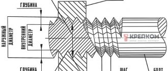
Its main elements are:
- internal, external and middle diameters;
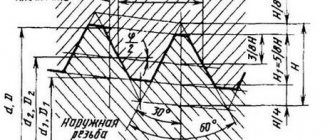
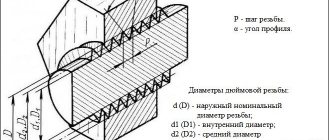
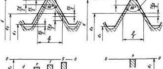
- profile is a cross section of a cut with a plane passing through the main axis of the part under consideration;
- profile angle - the angle formed by the sides of the profile;
- profile height is the length of the segment between the minimum and maximum cutting points in the cross-sectional plane of the axis in the direction orthogonal to the cutting guide;
- pitch - the length of the gap between two points of adjacent identical turns, measured parallel to the axis of the thread.
General information
The tip of the cutter, when moving at a constant feed speed along the rotating workpiece, cuts into, leaving a helical line on its surface (Fig. 4.42).
The inclination of the helix to the plane perpendicular to the axis of rotation of the workpiece depends on the rotation speed of the spindle with the workpiece and the feed of the cutter and is called the angle μ of the helix (Fig. 4.43). The distance between the helical lines, measured along the axis of the workpiece, is called the pitch P of the helical line. If a segment on the surface of a part equal to the pitch of the helix is turned onto a plane, then from the right triangle ABC we can determine
tgμ= P/(πd),
where d is the diameter of the workpiece along the outer surface of the thread.
When the cutter is deepened into the surface of the workpiece along the helical line, a helical surface is formed, the shape of which corresponds to the shape of the tip of the cutter. A thread is a helical surface formed on rotating bodies and used to connect, seal or ensure specified movements of machine parts and mechanisms. Threads are divided into cylindrical and conical.
Depending on the purpose of the threaded connection, threads of various profiles are used.
The thread profile is the contour of the thread section in a plane passing through its axis. Threads with acute-angled, trapezoidal and rectangular profiles are widely used.
Threads are left and right. A screw with a right-hand thread is turned clockwise (from left to right), and a screw with a left-hand thread is turned counterclockwise (from right to left). There are single-start and multi-start threads. A single-start thread is formed by one continuous thread, and a multi-start thread is formed by several threads equidistantly located on the surface of the part. The number of threads is easy to determine at the end of the part, where the threaded surface begins (Fig. 4.44, a and b).
There are strokes Ph and pitch P of multi-start threads. The stroke of a multi-start thread (GOST 11708-82) is the distance along a line parallel to the thread axis between any initial midpoint on the side of the thread and the midpoint obtained by moving the initial midpoint along a helical line at an angle of 360° between the same points of one turn one thread of thread, measured parallel to the axis of the part. The stroke of a multi-start thread is equal to the thread pitch multiplied by the number of starts:
Ph= kP,
where k is the number of visits.
This is interesting: Choosing a welding inverter - valuable recommendations from experts
Disadvantages of connections
There are not many negative aspects to this type of connection. One of them is the occurrence of high stress in the depressions. In addition, they cannot be used in devices and mechanisms that have high vibration, since the screws can unscrew on their own, which is not a good sign.
Therefore, it is necessary to monitor this, and if such a situation arises, correct the position of the screws.
Quality such as cost can be attributed to both positive and negative aspects.
Single-stroke threads cost significantly less than multi-stroke threads. Here everyone chooses according to personal preferences. Many design organizations use multi-pass threads, as they are reliable and durable.
So, we found out what this type of connection is, such as a trapezoidal thread, its dimensions, advantages and disadvantages.
Thread Features
Rectangular threads have a non-standard square profile, so standard parameters for pitch, diameter, cut size and stroke are not established for it. The profile depth of this type of cutting is equal to half the step. The main dimensions of threaded connections with a rectangular profile are defined in GOST 9150-81.
According to the method of formation, left and right rectangular threads are distinguished. The left type of cutting is created by a contour that rotates counterclockwise. The contour moves along an axis relative to the observer. A right-hand thread is formed by a contour that produces clockwise rotational movements. The movement is carried out along the axis in the direction from the observer.
A rectangular thread can be single-start (cut in the form of 1 turn). In this case, the load placed on the screws of the threaded connections will not be able to lower on its own without the influence of additional friction force. This advantage of single-pass cutting is due to the presence of self-braking properties. Multi-start threaded connections are also manufactured, where the cutting is carried out in the form of 2-3 separate turns located at an equal distance. The number of starts of a rectangular thread can be measured using the following formula: Z = L/S, where S is the step size and L is the stroke value.
Rectangular thread has many similar features to the trapezoidal tape type of cutting. Both types of cutting are used to transform a rotational type of motion into a translational one, have the property of self-braking and do not have precise manufacturing standards. Nevertheless, rectangular threads are inferior to trapezoidal threads in terms of strength and manufacturability. Also, tape thread has a simpler manufacturing technology, has high friction forces and does not require additional fixation. But it is inferior to threads with a rectangular cross-section in terms of efficiency. Nowadays, rectangular threads are gradually being replaced by trapezoidal threads in many areas of industry due to a large number of disadvantages.
How to cut on a lathe?
For example, cutting on a lathe using a cutter will look like this: the cutter moves along the axis of the rotating part, which moves back and forth in relation to the cutter, and with its pointed tip draws a screw-type line.
The helical line differs in the angle of its rise or increase. The magnitude of this angle is perpendicular to the axis of rotation, it is measured between the tangent and is determined by: the amount of feed of the cutting tool, which moves along the axis, with the rotational speed of the part.
Cutting internal and external
To cut internal or external threads, you need to use a rod cutter. Their production differs only in the shape of the cutter. For external applications, straight or bent incisors are used.
And for the internal ones, curved or straight incisors. The location of the cutter edge must coincide with the profile of the thread being processed.
Cutting with taps and dies
External threads are cut using dies. The part area is pre-processed. The diameter of the surface to be machined should be slightly smaller than the outer diameter of the thread.
First, a chamfer corresponding to the height of the thread profile is removed. Then the die is installed in the chuck (die holder).
And the speed is selected in accordance with the desired thread (it is indicated on the back of the machine).
Taps are often used for internal metric threads. As a rule, machine taps are used on the machine, this allows the part to be completed in one pass.
For threads made of hard, viscous materials, sets of 2–3 taps are used. In a set of two, the right one does 75% of the work, and the second one only brings it to the desired size.
In a set of three taps, the right or roughing one does 60% of the work, the middle (semi-finish) 30% of the work, and the third 10%.
Using Die Heads
Threading heads are used for pipes and bolts. They are installed in the machine, then the desired diameter is adjusted and moved along the pipe. They are able to carry out work with high precision.
Universal heads allow you to install dies from different companies. It is also possible to lubricate the combs and adjust the sizes; manual clamping is often found.
GOST requirements
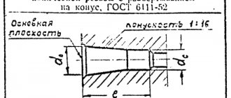
Basic requirements of GOST 6111-52:
- the deviation of the axis of the base plane to the nominal diameter should not exceed the thread pitch;
- the position of the base plane is specified by the distance from the end of the workpiece;
- the diameters of the tapered thread are located in a single main plane and are determined by the design section;
- the length of the external thread l2 is determined based on checking the average diameter with a corresponding ring gauge, and the external thread - with a plug;
- when screwing on pipes and couplings of nominal sizes, the plane of the thread must coincide with the end part of the coupling;
- the number of turns on the large diameter of the cone should not be less than two;
- the length from the base plane to the end of the tube can be reduced, but still meet other requirements of the standard;
- forming the cone with the center line should make an angle of 147'24".
Requirements GOST 6211-81
The values of the average d2 and internal d1 diameters must be calculated using the formulas:
d2=d-0.640327•P;
d1=d-1.280654•P;
where d is the outer diameter;
P - step.
- the length of the internal thread should be 0.8(l1-Δ1l2), where Δ1l2 are the values indicated in Table 2, GOST 6211-81;
- the distance of screwing the external thread onto the internal thread should be l1+Δ1l2;
- the displacement of the base plane is a total value determined by the pitch, the angle of inclination of the profile, the angle of the cone, the average diameter;
- Tolerances for the average diameter are indicated in Table 3, GOST 6211-81.
APPENDIX 1 Mandatory
CALCULATION FORMULAS ACCEPTED IN THE TOLERANCE SYSTEM FOR TRAPEZOIDAL MULTIPLE THREAD
Formulas for calculating the numerical values of tolerances of degrees of accuracy 4 - 9, the main deviations of make-up lengths, as well as rounding rules - according to GOST 9562.
Numerical values of tolerances of the 10th degree of accuracy for diameter d
2calculated using the formula
| , | (1) |
for diameter d
3- according to the formula
| . | (2) |
(Changed edition, Amendment No. 1).
Designation principles
The designation of threads in drawings is carried out according to the following rules.
- Indicate with solid thin and thick lines. The designation of an internal thread is a thin line along the outer diameter and a thick line on the internal one, and an external thread is indicated by a thick line along the outer diameter and a thin line on the internal one.
- If the part is projected onto a plane along the axis of rotation, then it is shown as solid straight lines. If - across, then this is an open contour, 0.75 of the total circumference. The ends of the arc should not lie on the axes of the part in the figure.
- The gap between the thin and thick lines should be more than 0.8 mm, but less than the step size.
- When designating metric threads in drawings perpendicular to the axis, chamfers are depicted only with structural significance.
External and internal thread types
Metric threads are standardized by several documents: GOST 8724-2004, GOST 2470-2004, GOST 9150-2002, GOST 1693-2005. They specify the requirements for dimensions, profile, pitches and tolerances.
Based on the product labeling, you can determine all the necessary parameters and type. Entry includes:
- a capital letter characterizing the type, or two capital letters - a type and a subspecies (for example, metric - M; metric conical - MK);
- a number expressing the nominal diameter in millimeters (M20 - metric with a nominal diameter of 20 mm);
- in the case of a small step, indicate its value in millimeters, using the multiplication sign - M20x1.5;
- in the case of a multi-start, add an indication of the stroke after the “x” and the step in parentheses - M20x3(P1) - metric with a diameter of 20 mm, three-start, where the step is 1 mm;
- when designating a left-hand thread, the Latin capital letters “LH” are written - M20LH or M20x3(P1)LH - also only left-handed.
In some cases, the marking may include additional parameters: make-up length, tolerances and fit. Their decoding is as follows:
- indication of tolerance for external thread M12x1.75-6g and for internal thread M12-6N;
- make-up length is expressed in capital Latin letters - S - shot (short), N - normal (normal), L - long (long), sometimes a numerical value of the length in millimeters is added in parentheses if the value is non-standard; for example, M12-6g-L(30);
- the fit is expressed as a fraction through the tolerance values for internal (numerator) and external (denominator) threads, for example, taking into account how left-hand threads are designated, the general appearance will be M12x1-6H/6g-LH.
Read also: Do-it-yourself search coil for a metal detector
The marking may also indicate the type and number of the standard.
By choosing the right type of metric thread and its geometric parameters, you can ensure high-quality fastening of parts, long-term operation of the product and savings on repairs and maintenance.
If you find an error, please select a piece of text and press Ctrl+Enter.
1.
In what units are metric threads measured: • In mm2 .
In what dimensions (units) is the pitch of an inch thread expressed: • Number of turns per length of 1 inch 3.
The set of 3 taps includes rough, medium and finishing taps. Which of them has the fence part with 3-4 cut threads: • Rough 4.
High-alloy steels have a total content of alloying elements • More than 10% 5.
For patterning, engraving work and for cleaning the following are used: • Needle files 6.
What material are rasps intended for processing • Very soft metals and non-metals 7.
For filing steel and cast iron, files are used • With double notch 8.
To mark the steel surface for drawing lines (marks), use: • Scribler 9.
Why is the surface of the part painted before scraping: • To identify irregularities 10.
In one working stroke, a scraper removes a layer of metal with a thickness of • 0.005-0.07 mm 11.
Countersinking is used for: • Processing of holes obtained by forging, stamping, casting and pre-drilled 12.
Countersinking is used for: • Enlarging the holes for the heads of bolts and screws 13.
A change in the shape and size of a product under the influence of external and internal forces is called: • Deformation 14.
Tools used for chopping metal • Used: hacksaw, pipe cutter, metal scissors 15.
It would seem that there is something complicated in the pipes? Connect and twist. But, if you are not a plumber or an engineer with a specialized education, then you will definitely have questions for answers to which you will have to go wherever you look. And most likely the first thing they look at is the Internet)
We have previously talked about the diameters of metal pipes in this material. Today we will try to clarify the threaded connections of pipes for various purposes. We tried not to clutter the article with definitions. The basic terminology is contained in GOST 11708-82, which everyone can familiarize themselves with.
Application of cutters
Thread cutting tools are required to cut threads using a lathe. They are made from high-speed steel, and the requirements for their characteristics are specified by the relevant GOST (18876-73). By design, such cutters are divided into the following types:
- prismatic;
- rod;
- round (disc).
A helical threaded groove on the surface of the workpiece is cut with a bent or straight cutter, and to form internal threads, straight and curved tools are required, which are fixed in a special mandrel. The top of the turning cutter, which is used to cut the turns, must have a configuration that fully corresponds to the profile of the thread being formed.
Cutters for cutting threads: a - rod; b - prismatic multi-profile; c - prismatic single-profile; g - disk multi-profile; d - single-profile disk; e - disk for internal thread; α—rear angle; γ — front angle; φ is the angle of the intake cone; h - installation height of the cutter axis
When forming a thread with a cutter, a number of features of this technology should be taken into account.
- The rake angle of a turning thread cutting tool depends on the characteristics of the material being processed. You can choose this angle within a fairly wide range: 0–25
0. So, if a thread is cut using a machine on workpieces made of ordinary steels, the rake angle should be 0 degrees; for high-alloy steels that withstand temperature loads well, the rake angle can be 5–10
0
. It can be greater, the higher the viscosity of the material, and the smaller, the higher the hardness and fragility of the metal from which the workpiece processed on the machine is made.
- The tip of the turning tool, which forms a helix on the workpiece, must have a shape identical to the thread profile.
- The rear side corners of the tool are chosen such that the surfaces of the cutter with which they are formed do not rub against the newly formed helical groove. Typically these angles are made equal on both sides of the turning tool. If the helix angle that characterizes the thread is less than 4 degrees, then such angles are chosen in the range of 3–5
0, if more than 4
0
, then 6–8 degrees.
- Internal threads are cut in already prepared holes, which are obtained by boring or drilling.
Threading cutters
Workpieces made of steel are processed on a lathe using tools with plates made of hard alloys T15K6, T14K8, T15K6, T30K4. If the part is made of cast iron, then to cut threads on it, use a tool with plates made of the following grades of hard alloys: VK4, V2K, VK6M, VK3M.
» data-lazy-type=»iframe» src=»data:image/gif;base64,R0lGODlhAQABAIAAAAAAAP///yH5BAEAAAAALAAAAAABAAEAAAIBRAA7″>
Multi-start thread
One of the parameters that determines the type of thread is the number of starts. It varies depending on the degree of complexity of the problems being solved. One of the most technologically complex threads is multi-start thread. This number can be two, three, four or more (this is quite rare). The higher the value of this parameter, the more difficult it is to perform. The most complex and time-consuming to produce is the four-start thread.
Regardless of the number, it has evenly spaced entries. They are placed at the same distance from each other, dividing the outer circumference of the part into an equal number of sectors. For example, a double-start thread will have two starts located symmetrically, one hundred and eighty degrees apart. For it, a stroke is the distance that is measured along the axis of the product (bolt, nut, shaft, etc.) between turns made in one pass, skipping other turns. With a single-pass, the concepts of step and move are identical; for a multi-pass, they have their own technical meaning. A move is always equal to a step multiplied by the number of moves made.
If the tooth has the shape of a classic trapezoid, it is called a multi-start trapezoidal thread. In cross section, a screw with a multi-start thread represents a figure with a given value of protrusions. Their number is equal to the number of sliced elements.
Using multi-start threads, the following problems are solved:
- increase joint strength (in many specialized joints);
- change the gear ratio (in gearboxes for various purposes);
- create a significant displacement of the nut along the propeller rod with a small number of revolutions made (for example, in the braking system of mine electric locomotives).
Multi-pass systems have the following marking sequence. The letter comes first. It means that it belongs to a specific type of thread: M - metric, UP or SP special multi-start. Next is a number that indicates the nominal diameter. After this number, the number of visits is noted, for example X2 means two visits. In parentheses, the number with the index “P” indicates the step value. For example, the marking of a multi-start thread M30X2 (P15) indicates that it is metric, with a diameter of 30 millimeters with the number of starts equal to two and a pitch of 15 millimeters.
For special types, the marking may look like Pack 22.5x(3x4.5). The first number 22.5 means the outer diameter, 3 indicates the number of passes, 4.5 indicates the pitch size. For a multi-pass design with such characteristics, the stroke value will be equal to the product of 3 and 4.5 mm, which is 13.5 mm. The number of passes can be determined visually by counting the number of turns on the end of a nut, screw or shaft.
According to the international designation system, the direction of the thread can be indicated: L - left, R - right. The multi-start thread itself is designated by the Latin letter S.
Internal thread cutting technology
As mentioned above, before starting work, you need to drill a hole, the diameter of which must exactly fit a thread of a certain size. It should be borne in mind: if the diameters of the holes intended for cutting metric threads are chosen incorrectly, this can lead not only to poor quality execution, but also to breakage of the tap.
Considering the fact that the tap, when forming threaded grooves, not only cuts the metal, but also pushes it, the diameter of the drill for making threads should be slightly smaller than its nominal diameter. For example, a drill for making M3 threads should have a diameter of 2.5 mm, for M4 - 3.3 mm, for M5 you should choose a drill with a diameter of 4.2 mm, for M6 threads - 5 mm, M8 - 6.7 mm, M10 - 8.5 mm, and for M12 - 10.2.
Read also: Nominal screw thread diameter
Table 1. Main diameters of holes for metric threads
Table 2. Diameters of holes for inch threads
All diameters of drills for GOST threads are given in special tables. Such tables indicate the diameters of drills for making threads with both standard and reduced pitches, but it should be borne in mind that holes of different diameters are drilled for these purposes. In addition, if threads are cut in products made of brittle metals (such as cast iron), the diameter of the thread drill obtained from the table must be reduced by one tenth of a millimeter.
The diameters of drills for metric threads can be calculated independently. From the diameter of the thread that needs to be cut, it is necessary to subtract the value of its pitch. The thread pitch itself, the size of which is used when performing such calculations, can be found out from special correspondence tables. In order to determine what diameter the hole needs to be made using a drill if a three-start tap is used for threading, you must use the following formula:
To = Dm x 0.8, where:
Do is the diameter of the hole that must be made using a drill,
Dm is the diameter of the tap that will be used to process the drilled element.
Scheme of cutting internal threads with a tap
The drivers into which the threaded tap is inserted can have a simple design or be equipped with a ratchet. You should work with such devices with tools fixed in them very carefully. To obtain high-quality and clean threads, rotating the tap clockwise, performed half a turn, must be alternated with turning it one-fourth of a turn against the thread.
The thread will be cut much easier if you use a lubricant during this procedure. The role of such a lubricant when cutting threads in steel products can be played by drying oil, and when processing aluminum alloys - alcohol, turpentine or kerosene. If such technical fluids are not at hand, then ordinary machine oil can be used to lubricate the tap and the thread being cut (however, it has less effect than the substances listed above).
Threaded connections are widely used in various mechanisms and machines. Bolts, studs, screws, nuts are universal, interchangeable fasteners. However, there are times when it is necessary to cut threads by hand. A specialized tool will help you do this job efficiently.
In mechanical engineering, there are three main systems of fastening threads: metric, inch and pipe.
Metric thread has become the most widespread. It has a triangular profile with an angle of 60˚. Its main parameters, diameter and pitch, are expressed in millimeters. Designation example: M16. This means that the thread is metric, has a diameter of 16 mm with a coarse pitch of 2.0 mm. If the step is small, then its value is indicated, for example, M16 * 1.5.
The diameters of inch and pipe threads are expressed in inches. The pitch is characterized by the number of threads per inch. The specified parameters are standardized, so it is always possible to select the necessary tool.
State standards
The production of such a complex metalworking element as a multi-start thread is carried out on the basis of established state and international standards. They complement each other and make it possible to harmonize the labeling systems that are used in the Russian Federation and by manufacturers in other countries. This is true for metric and inch measurement systems.
These standards include:
- Unified system of design documentation;
- GOST 24739-81. It contains standards describing the trapezoidal multi-entry structure.
- GOST 9484-81. This standard approves the possible profiles, what type and size the multi-start trapezoidal thread should be;
- GOST 25347-82. The standard establishes the permitted tolerances necessary for cutting and assembling finished structures.
Download GOST 9484-81
Download GOST 24739-81
Download GOST 25347-82
The listed standards make it possible to determine the outer and inner diameter, shape of the elements, pitch, stroke, number of passes, and the required drill diameter for preparing holes for future threads.