Send a request
Type of cone: standard, pointed, eccentric
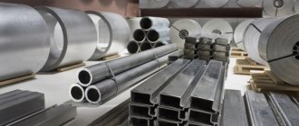
Materials: stainless steel, black steel, aluminum, copper, brass
Diameter: from 70 mm to 4000 mm
Thickness: from 0.5 mm to 20 mm
- Show more There are no more examples of this service.
The PROFIT STEEL company produces cones from various metals. We work with customer drawings and create parts based on our own designs. When choosing the type of metal and manufacturing method, the operating conditions of the structure are taken into account.
Calculators for calculating cone development sizes
Sometimes, while performing certain chores, the master is faced with the problem of making a cone - full or truncated.
This could involve operations on, say, thin sheet metal, flexible plastic, regular fabric, or even paper or cardboard. And the tasks are very different - making casings, adapters from one diameter to another, canopies or deflectors for a chimney or ventilation, funnels for gutters, a homemade lampshade. Or maybe even just a fancy dress for a child or crafts assigned by the labor teacher at home. Calculators for calculating cone development sizes
To roll a three-dimensional figure with given parameters from a flat material, you need to draw a development. And for this you need to calculate mathematically and transfer graphically the necessary exact dimensions of this flat figure. We will look at how this is done in this publication. Calculators for calculating the dimensions of the cone sweep will help us in this matter.
DIY chimney cap
House owners often resort to using elements in the form of various caps and umbrellas, which, as it seems at first glance, serve to decorate chimneys. At the same time, such attachments not only improve the aesthetic perception of the structure, but also provide useful functionality. Usually the so-called chimney canopy is made in-house, since this does not require serious knowledge and skills. Although, along with the simple design of these elements, there are quite intricate crafts that are problematic to build without the appropriate experience.
Design features
A chimney cap is a device designed to protect the pipe from moisture. The appearance of such canopies can be different, which depends both on the preferences of the owner of the house and on the configuration of the pipe.
Chimney caps include:
- umbrella - protection from precipitation, foreign objects and bird penetration installed on the top of the hood, the appearance of which has the shape of a pyramid, cone or corresponds to other geometry;
- apron - part of the cap responsible for protecting the top of the pipe from water flowing from the umbrella. Typically, the installation of this element is carried out when equipping a rectangular or square pipe. As a result, an increase in the service life of the chimney is guaranteed, since it is possible to practically eliminate the likelihood of corrosion and fungus;
- brackets – fastening elements, which are metal strips that allow you to connect the visor and the apron. Direct fastening in this case is carried out through the use of welding.
Keep in mind! It is quite possible to assemble a chimney cap yourself, but only if you want to install a fairly simple weather vane. Models that are more complex in terms of design features are much more profitable to order or buy.
If you have a choice, it is best to give preference to those models that are equipped with an opening lid. This will allow for preventive inspection of the chimney and its cleaning without any problems, which is associated with ease of access.
A long-lasting chimney cap can only be made of corrosion-resistant iron: galvanized steel, aluminum and copper. In the latter case, the proposed metal has a pronounced decorative character, since its shimmer in the sun can give your home a certain respectability.
Place a cap on the chimney pipe to extinguish sparks. This is one of its purposes. Therefore, the quality of the iron must be good, so it will not burn out for a long time.
Due to the fact that chimneys come in a variety of shapes and sizes, cap manufacturers also offer a wide range of products. If you decide to decorate your home and extend the life of the chimney, you will have to choose from a large assortment of weather vanes:
- Standard - a chimney umbrella in the form of a pyramid, for the manufacture of which sheet metal is used, and fastening to the apron is carried out using brackets.
- Four-slope - installed mainly on rectangular pipes made of brick. The shape corresponds to a hip roof with four slopes.
- With a semicircular umbrella - it is visually beautiful, but provides insufficient traction. Mainly used for installation on chimneys of houses built according to European standards.
- Flat - can often be found on Art Nouveau buildings. It has a rectangular shape and has the disadvantage of increased load on the brackets, which in some cases leads to their deformation. This is due to the flat roof of the hood, which prevents snow from rolling off. This fact determines the occurrence of the mentioned problem.
- Round with a cone-shaped umbrella - models without a drip, installed on round chimneys made of stainless steel.
How to create helical piles with your own hands?
The foundation on helical piles is gaining popularity in our region. Long service life, highest reliability, ease of installation in a short period of time, and the ability to be used on most types of soil have led to the wide spread of helical piles in personal house construction. Any owner can create helical piles with his own hands.
Calculators for calculating cone development sizes
A few words about the calculated parameters
It will not be difficult to understand the calculation principle by understanding the following diagram:
A truncated cone with defining dimensions and its development. A truncated cone is shown, but with a full one - the principle does not change, and calculations and construction become even simpler.
So, the cone itself is determined by the radii of the bases (lower and upper circles) R1 and R2 , and the height H. It is clear that if the cone is not truncated, then R2 is simply equal to zero.
The letter L indicates the length of the side (generator) of the cone. In some cases, it is already known - for example, you need to make a cone according to a sample or cut out material to cover an existing frame. But if it is unknown, it doesn’t matter, it’s easy to calculate.
The scan is shown on the right. For a truncated cone, it is limited by the sector of the ring formed by two arcs, external and internal, with radii Rb and Rs . For a full cone, Rs will also be zero. It is clearly seen that Rb = Rs + L
The angular length of the sector is determined by the central angle f , which in any case must be calculated.
All calculations will take literally a minute if you use the offered calculators:
Step 1 - determining the length of the generatrix L
(If it is already known, the step is skipped)
Step 2 - determining the radii of the inner and outer sweep arc
Radii are calculated one by one - with a choice in the corresponding field of the calculator.
Types of rolling
The main types of rolling include the following:
- Pipe rolling (flaring) - used to change the radius of the pipe.
- Sheet metal rolling
is the procedure of bending a sheet of metal into a radius.
Pipe rolling is carried out on pipe bending machines, which are capable of rolling pipes with a diameter of up to 30 cm. Angles, channels and other parts are processed using the same equipment.
Radius rolling is used for stainless, ferrous, galvanized metals of various thicknesses: steel, aluminum, copper. For sheets with a thickness of over 10 mm, heating is required. Metal sheets up to 10 mm thick are cold bent. One of the more complex technological processes of sheet metal rolling
- This is the making of cones. We also have equipment that produces conical and cylindrical shells.
If you need sheet metal rolling in Moscow
— our company is ready to perform custom-made services with high quality, at a high professional level. Our craftsmen have enormous experience and produce parts with the most accurate radius. They thoroughly know the operating principle of the equipment, scrupulously follow the technology, and adhere to all the nuances of metal processing.
Calculation of pile characteristics
The bearing capacity of a support is calculated for several reasons:
- blade diameter;
- blade depth;
- type of soil;
- soil resistance.
The number of piles for a building depends on:
- weight of the structure, including partitions and roofing;
- operational overload (weight of furniture and equipment);
- snow overload in winter.
The number of piles must be calculated individually, based on the topography of the site, structural and operational features of the structure.
Inclined cone development
Let us consider the procedure for constructing a scan of the lateral surface of an inclined cone using the approximation (approximation) method.
- We inscribe the hexagon 123456 into the circle of the base of the cone. We connect points 1, 2, 3, 4, 5 and 6 with the vertex S. The pyramid S123456, constructed in this way, with a certain degree of approximation is a replacement for the conical surface and is used as such in further constructions.
- We determine the natural values of the edges of the pyramid using the method of rotation around the projecting straight line: in the example, the i axis is used, perpendicular to the horizontal projection plane and passing through the vertex S. Thus, as a result of rotation of the edge S5, its new horizontal projection S'5'1 takes a position at which it is parallel to the frontal plane π2. Accordingly, S''5''1 is the natural value of S5.
- We construct a development of the lateral surface of the pyramid S123456, consisting of six triangles: S16, S65, S54, S43, S32, S21. The construction of each triangle is carried out on three sides. For example, △S16 has length S1=S''1'', S6=S''6''1, 16=1'6'.
The degree to which the approximate development corresponds to the actual one depends on the number of faces of the inscribed pyramid. The number of faces is chosen based on the ease of reading the drawing, the requirements for its accuracy, the presence of characteristic points and lines that need to be transferred to the development.
Transferring a line from the surface of a cone to a development
Line n lying on the surface of the cone is formed as a result of its intersection with a certain plane (figure below). Let's consider the algorithm for constructing line n on a scan.
- We find the projections of points A, B and C at which line n intersects the edges of the pyramid S123456 inscribed in the cone.
- We determine the natural size of the segments SA, SB, SC by rotating around the projecting straight line. In the example under consideration, SA=S''A'', SB=S''B''1, SC=S''C''1.
- We find the position of points A, B, C on the corresponding edges of the pyramid, plotting on the scan the segments SA=S''A'', SB=S''B''1, SC=S''C''1.
- We connect points A, B, C with a smooth line.
Selection of rolled metal
The durability and operational properties of piles are influenced by many reasons. The main one is the property of rolled metal of all components of the pile. In our country there are no precise rules, including a municipal standard, that would regulate all the properties of helical piles. Steels with a low carbon content - up to 0.25% - are unrivaled for the production of piles. When buying rolled metal, ask the dealer for a certificate of quality and documents confirming that it has passed tests in the Quality Control Department (technical control department).
The helical pile system consists of 3 parts:
- trunk
- tip
- helical blade
- head
An iron pipe is used as the shaft of the pile. These can be seamless pipes or with a welded seam. Quite often, used oil industry pipe is used for homemade piles.
The load-bearing capacity of the pile is ensured by a helical blade. The blade can be attached both to the tip itself and to the shaft of the pile. This is not of fundamental importance. In home conditions, ensuring a clear calculation and tight fit of the blade to the tip is very problematic, because, most importantly, the blade is mounted on the shaft of the pile.
The pile system provides two options for the tip:
- welded - a part of the pile shaft is used, which is narrowed into a cone;
- cast with a blade - welded to the shaft of the pile.
To reduce labor costs, you can use ready-made cast tips with helical blades, to which the pile shaft is welded. The use of a cast tip will ensure the correct entry of the auger turn, and there will also be no threat of blade breakage, guaranteeing the highest reliability of the product. In turn, the introduction of a ready-made tip increases the cost of a helical pile. For example, a cast tip for a 108 pipe from various manufacturers costs from about 700 rubles apiece.
Cone base
To find out the radius of the base of the conical frame, use a ruler to measure the diameter of the lower part of the workpiece, which is a paper (cardboard) side surface.
For greater accuracy, apply a ruler to the edges of the workpiece and measure the distance in two perpendicular directions. Calculate the average diameter and divide in half. As a result, the radius of the base of the paper cone is obtained.
- Using a compass, draw a circle on the prepared second sheet of paper, the radius of which is equal to half the diameter of the base of the cone. At this stage of production, you need to try on the base of the already made side surface to the drawn circle. And, if everything matches, then proceed to the next step.
- Having placed the leg of the compass in the center of the drawn circle, increase the expansion of the compass, making an allowance of 1.5 centimeters, and draw another circle.
- A circle is cut out along the line of the outer circle with scissors and cuts are made along the entire perimeter from the edge of the cut out circle to the line of the inner circle.
- The notches are bent to one side at an angle of 90 degrees. The result is the bottom of a cone with curved edges to connect to the side surface.
- All that remains is to coat the lower inner part of the sidewall with glue to a depth of 1.5 cm and carefully insert the manufactured bottom with notches inside the cone.
Source: https://ooocentrsvarki.ru/stanki/usechennyj-konus-svoimi-rukami.html
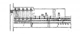
From a flat sheet to a round shell:
Rollers with an asymmetrical arrangement of rolls (Fig. 11) produce almost complete bending of the shell.
The most modern are four-roll machines (Fig. 12), which perform rolling and hemming of edges in one cycle. The bending radius of the shells is checked using templates. Possible defects in rolling of cylindrical shells are shown in Fig. 14.
Cones and transition elements in every strength and material quality
In addition to cones and transition parts, we also produce shells and extensions of any kind. Components that cannot be transported in one piece due to their size, we produce, as far as technically possible, in a number of segments that can be assembled on site to obtain the finished product.
High precision and reliability in forming technology - just in time
In production, we place great emphasis on outstanding quality and precision. There are many reasons why you might want to make a metal foil cone. Metal cones are used to block chimneys, even for certain types of outdoor fires and barbecues, and sometimes for decorative purposes. Folding sheet metal is easier than you might expect, so don't be intimidated by the process. Enter it completely, but with caution, of course.
Also, the methods for obtaining the desired shape are different.
Bending of conical shells is done in several ways:
1) By installing at an angle the middle roll for symmetrical three-roll machines and the side roll for asymmetrical three-roll and four-roll rollers (Fig. 15). 2) Flexible along the center line sequentially in different areas (Fig. 16) on rollers. First, the edges are hemmed, then the middle of the workpiece is bent in each section with reinstallations. This method leads to increased wear and tear on the equipment.
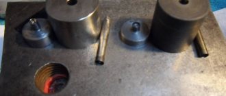
3) Bending of shells on rollers with replaceable conical rolls. This method is justified in serial and mass production. 4) Rollerless method for sheets up to 20 mm thick. In Fig. 17 shows the folding method. The edges 3 and 4 of the workpiece are fixed in supports 2 and 5, brought together, and the supports are simultaneously rotated in different directions. Next, the edges of the conical shell are joined using tacks and removed from the machine. 5) The most productive method is to manufacture conical shells in dies (Fig. 18). Before welding parts of the shells, they are pre-fixed to prevent deformation of the elements and ensure welding gaps. Aligning the edges is usually done with clamps and assembly rings for thin sheets (Fig. 19). Two clamps are installed on one shell at the ends.
The cylindricity of the shells is ensured by special devices with jacks that push the part apart. When assembling dimensional parts, tie strips and wedge connections are used (Fig. 20).
Manufacturing of a working cone to order
The pencil will draw a circle, and the small indentation that the compass left where it was supported should be marked. 2 Cut the circle using special metal foil scissors. Wear gloves so that the edges of the metal are very sharp. 3 Cut the circle in half. Using the support point of your compass as a guide and as your end point, cut a straight line there starting at both ends. You will now have a circle of metal foil with a slit that starts at one side and goes all the way to the center. 4 Overlap one side of the cut over the other. Starting at the gap, press the sheet pieces one on top of the other. At the same time, you will see that the circle begins to shrink and form a cone. Stop when necessary, depending on how deep you want it. 5 Tape on each side of the overlay. This will prevent the metal from moving and get rid of rough edges. Your metal blade taper is now complete. Wear gloves whenever you handle a metal blade to avoid cutting your hands. Metal blade Scissors for metal blade Compass with pencil Duct tape Gloves. The establishment of certain uniform rules finds its rationale in the need to guarantee, in relation to all professions subject to certification, the objectives required by certificates of professionalism.
Learn how to make a truncated cone or round transition with your own hands
In everyday life, of course, you have to do everything yourself if you have your own yard, house, dacha, construction. Perhaps a little advice in the article with sections on how to make a cone or transition with your own hands will help you around the house, without extra costs.
For example, let's take a bucket made of metal or other material. It has two different diameters. The smallest one is made at the bottom with a closed bottom. The bucket is made in the shape of a truncated cone.
Round transitions are used everywhere, for example ventilation, from one round diameter to another round diameter, also in the form of a truncated cone.
Take a random cone size with a diameter of 250 x 150 mm and a height of 180 mm (you have your own dimensions). Figure A.
We make a pattern of the part on which we will create the transition. The first diameter of 250 mm is multiplied by P = 3.14 and the result is 785 mm. Then we divide 785 mm into 10 parts. We divide the resulting amount of 78.5 mm into 2 parts. See the example in the figure.
Next, we draw a part template, using it we will make a cone pattern. Figure B.
We outline the part template 10 times. You get a development of a truncated cone. Figure B.
Locks or connections are indicated in yellow. How will you connect your right. Locks for tightness, can be used with bolts, self-tapping screws, welding seam, glue, overlap. The only thing we don’t forget to add to the connection. When you have completely traced the template, round off the straight ends slightly.
Next, after assembling the cone, bead the edge of the cone along the edges with a hammer to secure the straight shell. It is better to make the height of the shell more than 60 mm.
It is better to make a sample of the first pattern from paper cardboard, so as not to spoil the material.
Source: https://xn——dlckc9bidcgrpu.xn--p1ai/stroitelstvo/uchimsya-delat-usechennyj-konus-ili-kruglyj-perexod-svoimi-rukami.html
Metal bending on rollers
07 Dec 2013 Category: Mechanics |
Recently, I have received several requests from blog readers for help in solving the same problem: how to determine the final location of the middle roller (roll) when working on three-roll sheet bending rolls and profile benders...
...relative to the position of the outer rollers (rolls), which will ensure bending (rolling) of the workpiece with a certain specified required radius? The answer to this question will increase labor productivity when bending metal by reducing the number of runs of the workpiece until a suitable part is obtained.
In this article you will find theoretical
solving the problem. Let me make a reservation right away: I did not apply this calculation in practice and, accordingly, did not check the effectiveness of the proposed method. However, I am confident that in certain cases metal bending can be done much faster using this technique than usual.
Most often, in normal practice, the final location of the movable central roller (roll) and the number of passes until a suitable part is obtained is determined by the “poke method”. After a long (or not so long) development of the technological process on a test part, the coordinate of the position of the central roller (roll) is determined, which is used for further reconfiguration of the rollers, producing a batch of these parts.
The method is convenient, simple and good for a significant number of identical parts - that is, for mass production. In single or “very small-scale” production, when it is necessary to bend different profiles or sheets of different thicknesses with different radii, the loss of time for adjustment “at random” becomes catastrophically huge. These losses are especially noticeable when bending long (8...11 m) workpieces! While you make the pass..., while you take measurements..., while you rearrange the position of the roller (roller)... - and all over again! And so a dozen times.
Calculation in Excel of the location of the moving middle roller
Launch MS Excel or OOo Calc and get started!
General rules for formatting spreadsheets that are used in blog articles can be found here.
First of all, I would like to note that sheet bending rollers and profile benders of different models may have movable outer rollers (rollers), or they may have a movable middle roller (roller). However, for our task this is not of fundamental importance.
The figure below shows the calculation diagram for the problem.
At the beginning of the process, the part to be rolled lies on two outer rollers (rolls) having a diameter D
.
The middle roller (roller) with diameter d
is brought
until it touches the top of the workpiece
.
Next, the middle roller (roller) moves down to a distance equal to the design size H
, the roller rotation drive is turned on, the workpiece is rolled, the metal is bent, and the output is a part with a given bending radius
R
!
H
correctly, quickly and accurately . This is what we will do.
Initial data:
1. Diameter of the movable upper roller (roller) /for reference/ d
write in mm
to cell D3: 120
2. Diameter of support rollers (rolls) with rotation drive D
we write in mm
to cell D4: 150
3. Distance between the axes of the support outer rollers (rolls) A
in mm enter
to cell D5: 500
4. Height of the section of the part h
enter in mm
to cell D6: 36
5. Internal bending radius of the part according to drawing R
enter in mm
to cell D7: 600
Calculations and actions:
6. Calculate the estimated vertical feed of the upper roller (roll) H calc.
in mm
excluding springing
in cell D9: =D4/2+D6+D7- ((D4/2+D6+D7)2- (D5/2)2)(½) =45.4
H calculated =D/2+h+R— ((D/2+h+R)2- (A/2)2)(½)
7. Adjust the rollers to this size H calc.
and make the first run of the workpiece.
We measure or calculate the resulting internal radius from the chord and height of the segment, which we denote as R
and write the resulting value in mm
to cell D10: 655
8. We calculate what the calculated theoretical vertical feed of the upper roller (roll) should be H 0calc
in mm for the manufacture of a part with a radius
R
without taking into account springing
in cell D11: =D4/2+D6+D10- ((D4/2+D6+D10)2- (D5/2)2)(½)=41,9
H0calc =D/2+h+
R0 - ((D/2+h+ R0 )2- (A/2)2)(½)
9. But a part with an internal bending radius
R was obtained with the upper roll lowered to size Hcalc , and not H 0calc !!!
We calculate the correction for back springing
x
in mm
in cell D12: =D9-D11=3,5
x = H calc -
H 0calc
10. Since the radii R
and
R
have similar dimensions, then the same correction value
x
to determine the final actual distance
H
to which the upper roller (roller) must be moved down to obtain an internal radius
R
.
We calculate the final calculated vertical feed of the upper roller (roll) H
in mm taking into account springing
in cell D13: =D9+D12=48,9
Calculators for calculating cone development sizes
Sometimes, while performing certain chores, the master is faced with the problem of making a cone - full or truncated. This could involve operations on, say, thin sheet metal, flexible plastic, regular fabric, or even paper or cardboard. And the tasks are very different - making casings, adapters from one diameter to another, canopies or deflectors for a chimney or ventilation, funnels for gutters, a homemade lampshade. Or maybe even just a fancy dress for a child or crafts assigned by the labor teacher at home.
Calculators for calculating cone development sizes
To roll a three-dimensional figure with given parameters from a flat material, you need to draw a development. And for this you need to calculate mathematically and transfer graphically the necessary exact dimensions of this flat figure. We will look at how this is done in this publication. Calculators for calculating the dimensions of the cone sweep will help us in this matter.
Calculators for calculating cone development sizes
A few words about the calculated parameters
It will not be difficult to understand the calculation principle by understanding the following diagram:
A truncated cone with defining dimensions and its development. A truncated cone is shown, but with a full one - the principle does not change, and calculations and construction become even simpler.
So, the cone itself is determined by the radii of the bases (lower and upper circles) R1 and R2 , and the height H. It is clear that if the cone is not truncated, then R2 is simply equal to zero.
The letter L indicates the length of the side (generator) of the cone. In some cases, it is already known - for example, you need to make a cone according to a sample or cut out material to cover an existing frame. But if it is unknown, it doesn’t matter, it’s easy to calculate.
The scan is shown on the right. For a truncated cone, it is limited by the sector of the ring formed by two arcs, external and internal, with radii Rb and Rs . For a full cone, Rs will also be zero. It is clearly seen that Rb = Rs + L
The angular length of the sector is determined by the central angle f , which in any case must be calculated.
All calculations will take literally a minute if you use the offered calculators:
Step 1 - determining the length of the generatrix L
(If it is already known, the step is skipped)
Step 2 - determining the radii of the inner and outer sweep arc
Radii are calculated one by one - with a choice in the corresponding field of the calculator.
Source: https://stroyday.ru/kalkulyatory/obshhestroitelnye-voprosy/kalkulyatory-rascheta-razmerov-razvertki-konusa.html