Thread cutters
TO
category:
Turning
Thread cutters
Next: Setting up a screw-cutting lathe to cut threads with a cutter
Threads with high requirements for coaxiality with other surfaces are made with thread cutters on a lathe configured for a feed corresponding to the pitch of the thread being cut.
There are high-speed and carbide thread cutters for cutting external and internal threads. The profile of the thread cutter corresponds to the profile of the thread being cut: for a metric thread, the profile angle e = 60°, for an inch thread £ = 55°. During the cutting process, some “breaking” of the thread profile is possible. Therefore, in fact, the profile of the cutter is underestimated: for cutters made of high-speed steel by 10-20', for carbide cutters by 20-30'.
The sharpening of threaded cutters is controlled using a special template. To ensure that when cutting large-pitch threads, the rear surfaces of the cutter head do not rub against the walls of the threaded grooves, two methods are used: the first is to make the rear angle of the side edge on the side where the feed of the caliper is directed during cutting, making it larger than the angle of inclination of the thread. For right-hand thread azate. left = « + a, and for a left-hand thread a3aT.npair = D + a, where and is the angle of the thread (Fig. 229, a). A cutter sharpened in this way has a negative rake angle (-y2) at the right edge (for right-hand threads), which is undesirable, as it increases the roughness of the thread. To avoid this drawback, a groove is sharpened on the front surface of the cutter along the right cutting edge (for right-hand threads) or along the left cutting edge (for left-hand threads) to facilitate chip flow; second - the cutter is sharpened with the same rear angles o = a2 on the right and left edges, but when installed, it is turned by the angle of the helix of the turns. For this purpose, a holder with a rotating head and divisions is used. A VNII thread cutter with mechanical fastening of a rhombic carbide plate is shown in Fig. 231. The plate is held by a clamp in a recess that is created in the holder.
1. THREADED CUTTERS: a—cutters in operation, b—geometry of a carbide threaded cutter; incisors. 1 - external. 2 - internal
2. INSTALLATION SCHEME OF A THREADED TURN a - cutter without a point, b - cutter with a point on the front surface
3. Threaded cutter installed with a rotation: a - cutter without a point, b - cutter with a point on the front surface, c - holder with a rotating head for a threaded cutter; 1 - cutter. 2 - screw. 3 - rotating head. 4 - body. 5 -1 screw
4. Threaded cutter with mechanical fastening of a rhombic plate: 1 - holder. 2 — support plate. 3 - cutting blade. 4 - clamping bar (clamp)
5. THREADED CUTS, SHARPENED ON THE FRONT SURFACE: a - prismatic, b - disk
To reduce the number of regrinds and simplify regrinding, as well as reduce the time for replacing a cutter, prismatic and disk thread cutters are widely used, grindable only along the front surface. To cut threads in through holes (with a free exit of the cutter), thread dies are often used, the profile resembling a tap, i.e., having a intake (with an ever-increasing height of the elementary threaded cutters) and a calibrating part. With this tool, the thread is cut to the full height of the profile in one pass. Combs are divided into rod, prismatic and round.
6. THREADED DIGS: a - rod, b - prismatic, c - round for external threads, d - round for internal threads; 11 - intake part of the comb
7. DIAGRAM FOR SETTING UP A SCREW-CUTTING LATHE FOR THREADING WITH A CUTTER
Topic 6.1. Thread cutting with cutters
Threading cutters are used to cut internal and external threads in single and small-scale production, as well as during repair work.
Like turning cutters, threaded cutters are secured, based on the lower supporting planes, in tool holders on the supports of screw-cutting lathes. To cut a thread with an undistorted profile, the main cutting edge of the thread cutter must lie entirely in a plane (usually horizontal) passing through the axis of rotation of the workpiece, and be located strictly symmetrically relative to the plane perpendicular to the axis of the workpiece being processed, which is achieved by using installation templates.
Threads with small pitches ( P
< 1 mm) are cut with profile thread cutters.
Threads with medium and large pitches ( P
> 1 mm) are cut with a set of cutters, consisting of a preliminary cutter that cuts out the main part of the allowance, and a profile finishing cutter that finally forms the profile of the thread turns.
Thread cutting with profile thread cutters
. The thread cutter has a profile that matches the profile of the thread. The tip of the cutter, which forms the cavity of the threaded profile, is subject to severe loading conditions during the cutting process, and its strength is insufficient when cutting threads to the entire depth of the profile at once. Therefore, thread cutting with a profile cutter is carried out in several passes.
In order for the cutter to return to its original position without axial displacement during repeated passes, the kinematic connection between the support group and the machine spindle, which is carried out when cutting threads through a lead screw and a falling worm, must not be disrupted. Therefore, the movement of the cutter to its original position is carried out by reversing the rotation of the spindle and moving the support group. At the moment of reverse, the tip of the cutter should not be in contact with the metal of the workpiece to avoid breakage. To do this, you first need to machine a groove for the tip of the cutter to exit. The groove width f is normalized and its values are given in reference literature. To prevent friction from the rear wheels when reversing
Rice. 6.1.1. Scheme of operation of a profile thread cutter
surfaces of the cutter along the thread surface cut during the previous pass and damage caused by friction, the cutter is moved away from the workpiece being processed. In Fig. 6.1.1 shows a diagram of the installation and movement of a profile thread cutter during processing. A cyclogram of the cutter movement is also shown here. Movement A2 is a working pass, during which the next layer of metal in the thread is removed. It consists of the length of the thread being cut l3, as well as the short run ∆ l
1 and overtravel ∆l2.
The reverse movement A
4 along the length is equal to the working one. The transverse feed A1 on the next pass is slightly larger than the feed A3 of the previous one.
Thus, cutting off the entire allowance from the workpiece and forming a finished helical groove of a complete threaded profile is carried out in i repeated working passes of the cutter. In the intervals between working passes, the transverse movement of the machine support imparts a transverse feed to the threaded cutter
S = H/i,
where n is the height of the threaded profile being cut.
In Fig. 6.1.2. shows a diagram of the sequential cutting of the allowance with a profile threaded cutter, which shows the positions of the cutting edges of the cutter in the process of forming the full profile of the threaded groove. The cross section of the layer cut during one pass is highlighted in the diagram by hatching.
Rice. 6.1.2. Scheme of cutting with a profile thread cutter and its geometric parameters
Geometric parameters of profile thread cutter
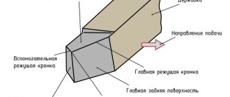
. With a profile thread cutter (Fig. 6.1.2), three cutting edges are involved in cutting and profiling the thread being cut: 1-2 on the blade of the cutter tip, 1-3 on the left straight profile blade, 2-4 on the right straight profile blade. All three cutting edges are the main ones. Profile thread cutters do not have auxiliary cutting edges and, accordingly, auxiliary blades.
By general definition, the leading angle φ is measured between the main cutting edge and the line on which the feed rate vector v
s
. Consequently, on the right and left side main cutting edges the main angle is φп = φ
l
= α
о/2
, where α
о
is the angle at the top of the threaded profile being cut (for metric threads α
о
= 60°). At the cutting edge of the apex blade, the leading angle is φп = 90°.
All the main cutting edges of the cutter, as mentioned above, lie in a horizontal plane passing through the axis of rotation of the workpiece being processed. The cutting speed vectors at all points of the main cutting edges are perpendicular to this plane, therefore the inclination angle of the main cutting edges of profile thread-cutting tools is λ = 0. For the same reason, the rake angle on profile thread-cutting tools is y = 0.
On the blade there are 1-2 cutter apexes, the clearance angle α ≈ 8...10° (Fig. 6.1.2). It is measured in a plane perpendicular to edge 1-2 and is the same at each point. On the left and right profile sides 1-3 and 2-4 clearance angle α
δ
is measured in planes perpendicular to the side blades (in Fig. 6.1.2, sectional plane A - A).
The value of the lateral clearance angle aa can be expressed through the value of the clearance angle α
δ
blade 1-2 incisor apex.
From the diagram in Fig. 6.1.2 tan αδ = E2 /h;
tan α = E1 /h,
where h is the height of the cutter. Dividing the right and left sides of the equations by each other, we obtain tan α
δ
/ tan α = E2 / E1 = sin φ = sin α0/2 ,
whence tan α
δ
= tan α
sin(
α
0/
2 ).
Thickness of the cut layer
On the blade of the cutter apex, the leading angle ( φ
= 90° and therefore the greatest thickness of the cut layer
is a
= S, where S is the feed, mm/pass. On the left and right side profile main blades, the leading angle
φ
=
α
0/2 and here the thickness of the cut layer
α
δ = S sin (
α
0/
2).
To cut high-quality threads, the thickness of the cut layer in one cutter pass is 0.02 mm < a < 0.2 mm, and, in addition, the thread cutting process must be carried out using oil-based lubricating and cooling fluids.
Pre-threading
. The section of the trough-shaped layer, cut in one pass with a profile threaded cutter (shaded in Fig. 6.1.2), has high rigidity, which makes it difficult to form and remove the cut chips. To facilitate cutting conditions when cutting threads with large and medium pitches, processing is carried out sequentially with two cutters. First, the main part of the allowance for the formation of a threaded turn is cut off with a rough thread cutter (contour 3′-1′-2'4′ in Fig. 6.1.3). Then the final processing and profiling of the threaded thread is carried out using a finishing profile thread cutter.
Rice. 6.1.3. Scheme of cutting the allowance with a rough thread cutter and its geometric parameters
The roughing thread cutter has a one-sided main cutting edge 3-1-2 consisting of two segments. In this case, section 1-2 at the tip of the cutter can be either straight or curved (made along the radius r
). The rough thread cutter is mounted on the rotary slide of the caliper, the guides of which are installed parallel to the right side of the thread being cut. The main cutting edge 1-3 is sharpened so that when the cutter is installed on the caliper slide, as indicated above, it occupies a position parallel to the left side of the thread being cut.
The feed S of the rough thread cutter is carried out in the intervals between each of the i working passes of the cutter by manually moving the slide along the right side of the thread being cut. The feed size S per pass can be either variable or constant.
In the latter case
S = (H - ∆H
)/
,
where H is the total allowance (height of the threaded profile); ∆H
— allowance left for final finishing with a profile thread cutter;
α0
is the angle of the threaded profile.
The diagram of sequential cutting of the allowance with a rough thread cutter is shown in Fig. 6.1.3. In this case, layers are cut off in one pass, one of which is shaded for example. This cross-sectional shape of the cut layer facilitates the formation and removal of chips. With a constant feed rate for each pass, the roughing thread cutter cuts layers of an increasingly larger cross-sectional area. Therefore, it is better to use a variable feed, and during the first two or three passes, cutting can be carried out with a higher feed, and thread cutting will be completed in fewer of them.
Layer thickness
, cut by section 1-2 of the main cutting blade,
a' = S cos
(
α0
/
2
),
and section 1-3 of the main blade (6.1.3)
a = S sin α0
.
Layer width
b', cut by section 1-2, is equal to the length of this blade and is constant for all i working passes, and the width b of the layer cut by section 1-3 is variable and increases during each subsequent pass. The current width of the layer cut in the i-th pass with a symmetrical thread profile is equal to
bi= i S.
Geometric parameters of rough thread cutter
. When doing the main cutting work, the 1-2 top and 1-3 left side blades of the roughing thread cutter are the main blades. On the right side profile side of the rough thread cutter there is an auxiliary blade, which is involved in cutting off the allowance layer at a length equal to the feed per pass.
On the cutting edge 1-2 tips of the cutter, the main angle φ
= 90° +
α0
./2.
On the left side cutting edge 1-3, the main lead angle is φ
=
α0
.. To eliminate the friction of the auxiliary flank surface of the cutter on the surface of the thread being cut, the auxiliary cutting edge is sharpened at an auxiliary lead angle
φ
1 = 2..5°.
Thus, the profile angle of the rough thread cutter between section 1-3 of the main blade and the auxiliary blade is less than that of the finishing profile thread cutter and is equal to ( α0
. -
φ
1).
Section 1-3 of the main blade of the rough thread cutter lies in a horizontal plane passing through the axis of rotation of the workpiece. This horizontal plane is perpendicular to the velocity vector v and therefore in this section the angle of inclination of the main cutting edge λ
.
= 0. On the blade of the tip of the cutter 1-2 with a rake angle γ
≠0, the angle of inclination of the cutting edge λ ≠ 0.
Roughing thread cutters, like turning cutting tools, have a rake angle γ
measured in a plane perpendicular to the projection of the main cutting edge onto the horizontal plane (for blade 1-3, the angle γ is shown in section A - A in Fig. 16.4).
Typically γ
= 15. 20°.
Relief angle α
on roughing thread cutters it is measured in the same plane as the rake angle γ. The value of the rear angle is taken within
α =
8. 10°.
Threading cutters are used to cut internal and external threads in single and small-scale production, as well as during repair work.
Like turning cutters, threaded cutters are secured, based on the lower supporting planes, in tool holders on the supports of screw-cutting lathes. To cut a thread with an undistorted profile, the main cutting edge of the thread cutter must lie entirely in a plane (usually horizontal) passing through the axis of rotation of the workpiece, and be located strictly symmetrically relative to the plane perpendicular to the axis of the workpiece being processed, which is achieved by using installation templates.
Threads with small pitches ( P
< 1 mm) are cut with profile thread cutters.
Threads with medium and large pitches ( P
> 1 mm) are cut with a set of cutters, consisting of a preliminary cutter that cuts out the main part of the allowance, and a profile finishing cutter that finally forms the profile of the thread turns.
Thread cutting with profile thread cutters
. The thread cutter has a profile that matches the profile of the thread. The tip of the cutter, which forms the cavity of the threaded profile, is subject to severe loading conditions during the cutting process, and its strength is insufficient when cutting threads to the entire depth of the profile at once. Therefore, thread cutting with a profile cutter is carried out in several passes.
In order for the cutter to return to its original position without axial displacement during repeated passes, the kinematic connection between the support group and the machine spindle, which is carried out when cutting threads through a lead screw and a falling worm, must not be disrupted. Therefore, the movement of the cutter to its original position is carried out by reversing the rotation of the spindle and moving the support group. At the moment of reverse, the tip of the cutter should not be in contact with the metal of the workpiece to avoid breakage. To do this, you first need to machine a groove for the tip of the cutter to exit. The groove width f is normalized and its values are given in reference literature. To prevent friction from the rear wheels when reversing
Rice. 6.1.1. Scheme of operation of a profile thread cutter
surfaces of the cutter along the thread surface cut during the previous pass and damage caused by friction, the cutter is moved away from the workpiece being processed. In Fig. 6.1.1 shows a diagram of the installation and movement of a profile thread cutter during processing. A cyclogram of the cutter movement is also shown here. Movement A2 is a working pass, during which the next layer of metal in the thread is removed. It consists of the length of the thread being cut l3, as well as the short run ∆ l
1 and overtravel ∆l2.
The reverse movement A
4 along the length is equal to the working one. The transverse feed A1 on the next pass is slightly larger than the feed A3 of the previous one.
Thus, cutting off the entire allowance from the workpiece and forming a finished helical groove of a complete threaded profile is carried out in i repeated working passes of the cutter. In the intervals between working passes, the transverse movement of the machine support imparts a transverse feed to the threaded cutter
S = H/i,
where n is the height of the threaded profile being cut.
In Fig. 6.1.2. shows a diagram of the sequential cutting of the allowance with a profile threaded cutter, which shows the positions of the cutting edges of the cutter in the process of forming the full profile of the threaded groove. The cross section of the layer cut during one pass is highlighted in the diagram by hatching.
Rice. 6.1.2. Scheme of cutting with a profile thread cutter and its geometric parameters
Geometric parameters of profile thread cutter
. With a profile thread cutter (Fig. 6.1.2), three cutting edges are involved in cutting and profiling the thread being cut: 1-2 on the blade of the cutter tip, 1-3 on the left straight profile blade, 2-4 on the right straight profile blade. All three cutting edges are the main ones. Profile thread cutters do not have auxiliary cutting edges and, accordingly, auxiliary blades.
By general definition, the leading angle φ is measured between the main cutting edge and the line on which the feed rate vector v
s
. Consequently, on the right and left side main cutting edges the main angle is φп = φ
l
= α
о/2
, where α
о
is the angle at the top of the threaded profile being cut (for metric threads α
о
= 60°).
At the cutting edge of the apex blade, the leading angle is φп = 90°. All the main cutting edges of the cutter, as mentioned above, lie in a horizontal plane passing through the axis of rotation of the workpiece being processed. The cutting speed vectors at all points of the main cutting edges are perpendicular to this plane, therefore the inclination angle of the main cutting edges of profile thread-cutting tools is λ = 0. For the same reason, the rake angle on profile thread-cutting tools is y = 0.
On the blade there are 1-2 cutter apexes, the clearance angle α ≈ 8...10° (Fig. 6.1.2). It is measured in a plane perpendicular to edge 1-2 and is the same at each point. On the left and right profile sides 1-3 and 2-4 clearance angle α
δ
is measured in planes perpendicular to the side blades (in Fig. 6.1.2, sectional plane A - A).
The value of the lateral clearance angle aa can be expressed through the value of the clearance angle α
δ
blade 1-2 incisor apex.
From the diagram in Fig. 6.1.2 tan αδ = E2 /h;
tan α = E1 /h,
where h is the height of the cutter. Dividing the right and left sides of the equations by each other, we obtain tan α
δ
/ tan α = E2 / E1 = sin φ = sin α0/2 ,
whence tan α
δ
= tan α
sin(
α
0/
2 ).
Thickness of the cut layer
On the blade of the cutter apex, the leading angle ( φ
= 90° and therefore the greatest thickness of the cut layer
is a
= S, where S is the feed, mm/pass. On the left and right side profile main blades, the leading angle
φ
=
α
0/2 and here the thickness of the cut layer
α
δ = S sin (
α
0/
2).
To cut high-quality threads, the thickness of the cut layer in one cutter pass is 0.02 mm < a < 0.2 mm, and, in addition, the thread cutting process must be carried out using oil-based lubricating and cooling fluids.
Pre-threading
. The section of the trough-shaped layer, cut in one pass with a profile threaded cutter (shaded in Fig. 6.1.2), has high rigidity, which makes it difficult to form and remove the cut chips. To facilitate cutting conditions when cutting threads with large and medium pitches, processing is carried out sequentially with two cutters. First, the main part of the allowance for the formation of a threaded turn is cut off with a rough thread cutter (contour 3′-1′-2'4′ in Fig. 6.1.3). Then the final processing and profiling of the threaded thread is carried out using a finishing profile thread cutter.
Rice. 6.1.3. Scheme of cutting the allowance with a rough thread cutter and its geometric parameters
The roughing thread cutter has a one-sided main cutting edge 3-1-2 consisting of two segments. In this case, section 1-2 at the tip of the cutter can be either straight or curved (made along the radius r
). The rough thread cutter is mounted on the rotary slide of the caliper, the guides of which are installed parallel to the right side of the thread being cut. The main cutting edge 1-3 is sharpened so that when the cutter is installed on the caliper slide, as indicated above, it occupies a position parallel to the left side of the thread being cut.
The feed S of the rough thread cutter is carried out in the intervals between each of the i working passes of the cutter by manually moving the slide along the right side of the thread being cut. The feed size S per pass can be either variable or constant.
In the latter case
S = (H - ∆H
)/
,
where H is the total allowance (height of the threaded profile); ∆H
— allowance left for final finishing with a profile thread cutter;
α0
is the angle of the threaded profile.
The diagram of sequential cutting of the allowance with a rough thread cutter is shown in Fig. 6.1.3. In this case, layers are cut off in one pass, one of which is shaded for example. This cross-sectional shape of the cut layer facilitates the formation and removal of chips. With a constant feed rate for each pass, the roughing thread cutter cuts layers of an increasingly larger cross-sectional area. Therefore, it is better to use a variable feed, and during the first two or three passes, cutting can be carried out with a higher feed, and thread cutting will be completed in fewer of them.
Layer thickness
, cut by section 1-2 of the main cutting blade,
a' = S cos
(
α0
/
2
),
and section 1-3 of the main blade (6.1.3)
a = S sin α0
.
Layer width
b', cut by section 1-2, is equal to the length of this blade and is constant for all i working passes, and the width b of the layer cut by section 1-3 is variable and increases during each subsequent pass. The current width of the layer cut in the i-th pass with a symmetrical thread profile is equal to
bi= i S.
Geometric parameters of rough thread cutter
. When doing the main cutting work, the 1-2 top and 1-3 left side blades of the roughing thread cutter are the main blades. On the right side profile side of the rough thread cutter there is an auxiliary blade, which is involved in cutting off the allowance layer at a length equal to the feed per pass.
On the cutting edge 1-2 tips of the cutter, the main angle φ
= 90° +
α0
./2.
On the left side cutting edge 1-3, the main lead angle is φ
=
α0
.. To eliminate the friction of the auxiliary flank surface of the cutter on the surface of the thread being cut, the auxiliary cutting edge is sharpened at an auxiliary lead angle
φ
1 = 2..5°.
Thus, the profile angle of the rough thread cutter between section 1-3 of the main blade and the auxiliary blade is less than that of the finishing profile thread cutter and is equal to ( α0
. -
φ
1).
Section 1-3 of the main blade of the rough thread cutter lies in a horizontal plane passing through the axis of rotation of the workpiece. This horizontal plane is perpendicular to the velocity vector v and therefore in this section the angle of inclination of the main cutting edge λ
.
= 0. On the blade of the tip of the cutter 1-2 with a rake angle γ
≠0, the angle of inclination of the cutting edge λ ≠ 0.
Roughing thread cutters, like turning cutting tools, have a rake angle γ
measured in a plane perpendicular to the projection of the main cutting edge onto the horizontal plane (for blade 1-3, the angle γ is shown in section A - A in Fig. 16.4).
Typically γ
= 15. 20°.
Relief angle α
on roughing thread cutters it is measured in the same plane as the rake angle γ. The value of the rear angle is taken within
α =
8. 10°.
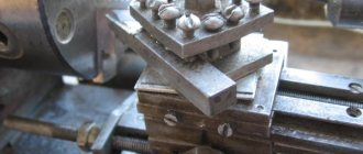
Internal thread cutter. We make a brush - an oil can.
Another cutter for the lathe arrived to me. Writing simply about a chisel is boring. Three phrases, two photos and that’s it. So I decided to respond to criticism in one of the comments to the previous review. Experienced readers reproached me that it is necessary not to drip oil onto the part from an oil can when cutting on a machine, but to apply it with a brush. And I decided to cross the brush with the oil can, and at the same time test the new cutter. What came out of this - look under the cut. First, I’ll tell you a little about the hero of the review. Thread cutter for internal threads with replaceable blades.
I used to use quick cutters. It’s frankly inconvenient to sharpen and after a couple of sharpenings you can make a new one.
The cutter arrived in the amount of three pieces and with a dozen replacement blades.
Why do I need three identical incisors? One for a lathe, the second for a milling machine (there are plans to attach a CNC to it and cut threads), but the third cutter is really superfluous. I’ll give it to one of my friends who has a homemade one with a lathe. Any machine operator will be happy with such a gift. I judge by myself.
Marking of cutter holder SNR0010K11. 11IR A60 record. Cutter length 125 mm, diameter 10 mm.
Each cutter comes complete with a screwdriver with a torx shank.
The quality of the cutter is excellent, the smooth holder is made of steel, reminiscent of the feel of St45. However, this applies to almost all modern Chinese incisors. Their industry has been making high-quality and reliable tools for a long time. Well, at least in the field of metalworking. Over the past 6 years, I have not encountered any obvious defects or any flaws. Maybe I was lucky, but rather this is the norm.
As can be seen from the geometry of the cutter itself, its main purpose is cutting internal threads or fine internal boring.
Let's return to the oil can.
Our starting materials will be: a brush from the nearest store for 6 rubles, a bottle, and a small aluminum blank
We trim the workpiece, bore a hole for the screw ring, cut off
We grind out the body of the tassel. At the end of the spout we make an internal cone. This will allow us to collect excess oil after use.
We grind to the size of the external thread, do not forget about the groove for the exit of the thread cutter
Cutting the thread
And finally the time has come for the hero of today’s review to act. We cut the internal thread in the ring that we cut off earlier. The cutter showed its best side. The thread is smooth, shiny, without burrs or roughness.
Boring a hole in the bottle cap
Next is the most important operation. We insert the bristles into the body of our brush and fill it with glue. There is a wire inside the bristles.
After the glue dries, we pull out the wire and in its place an oil access channel is formed
A responsible operation - we trim the villi)))
Putting all the details together
Add oil and test. Hurray, everything works, the experimental screwdriver is covered with a layer of oil)))
Here's what we got
And as usual, a video with the process of making an oil brush
Summary. An excellent cutter, well made, and also performed remarkably well in its work. Saves time on sharpening or making high-speed steel thread cutters. I really liked it.
The product was provided for writing a review by the store. The review was published in accordance with clause 18 of the Site Rules.