Machining of cylindrical holes
In many machine parts, holes are an important element. The parts are connected through the holes with screws or bolts. The holes are used to install bearings and supply lubricant or coolant. The working cavities of engines and compressors are also openings, etc.
Holes are divided into through holes (processed for passage) and blind holes (processed to a certain depth). In shape they are smooth, stepped, with grooves. Holes whose length exceeds 5 diameters are called deep.
To create a specific connection to the shaft, holes are made with a certain accuracy in size, shape, location and roughness in accordance with the technical requirements of the working drawing.
Machining of cylindrical holes is carried out on lathes. Holes are processed by drilling, reaming, boring, countersinking, and reaming. Each of these methods is characterized by a certain processing accuracy and, therefore, is used depending on the requirements for a given hole.
- Drilling holes
- Hole alignment
- Boring holes
- Reaming holes
- Countersinking holes
Holes are subject to various requirements in terms of accuracy, axis straightness, correct geometric shape, and surface roughness.
Cylindrical holes are smooth, stepped, with a groove (undercut). The holes can also be through or blind (Fig. 70, a-e).
The diameters of the holes are controlled with a caliper with an accuracy of up to 0.1 mm or 0.25. When measuring with a ShTs-P caliper, the thickness of the jaws is taken into account with an accuracy of 0.05 mm. Holes with a diameter of 120 mm and above are measured with a micrometer bore gauge with an accuracy of 0.01 mm. Deep holes of large diameter (for example, cylinder cavities) are controlled by an indicator bore gauge, which is pre-set to the size of a reference ring or micrometer. The indicator shows the deviation from the set size with an accuracy of 0.01 mm.
In large-scale and mass production, holes are controlled by limiting plug gauges. If the pass-through plug PR passes into the hole without effort, and the non-go-through plug does not pass through, then the size of the hole is within the tolerance. To control holes with a diameter of 80 mm or more, cut and plate plugs are used. Such plugs are lighter, in addition, they can detect the ovality of a hole by checking the hole in two mutually perpendicular directions. Before checking with a plug gauge, the hole cavity is cleared of chips and wiped. Cleaning the hole and checking the size is allowed only after the spindle has completely stopped rotating. Plug gauges are stored in an upright position or placed on a foam panel.
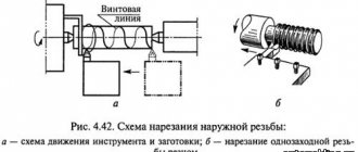
Processing of workpieces on screw-cutting lathes
Turning
Lecture outline
Lecture 2. Machining on lathes
1. Turning
2. Processing of workpieces on screw-cutting lathes
3. Processing of workpieces on turret lathes
4 Processing of workpieces on rotary lathes
5. Processing on single-spindle automatic and semi-automatic lathes
6. Processing on multi-spindle semi-automatic and automatic lathes
The main methods of machining by cutting, accompanied by chip removal, can be implemented on metal-cutting machines of certain groups: 1) turning; 2) boring; 3) drilling, countersinking, reaming; 4) milling; 5) planing, chiselling; 6) broaching, stitching; 7) gear cutting; grinding, finishing, polishing.
Turning is the most common method of processing parts such as rotating bodies (shafts, axles, journals, disks, flanges, couplings, rings, bushings, nuts, etc.). On lathes it is possible to perform rough, semi-finishing and finishing turning and boring of cylindrical, conical, spherical and shaped surfaces; cutting flat end surfaces, turning external and internal grooves, cutting external and internal threads, drilling, countersinking, reaming holes, etc.
Turning of surfaces is carried out with a rotational main movement of the workpiece and a translational (longitudinal, transverse or inclined relative to the axis of the workpiece) movement of the tool feed. Shaping of surfaces when cutting with longitudinal feed - using the trace method, when cutting with a transverse feed of the tool - using the copying method.
The turning group includes screw-cutting lathes, turret lathes, rotary lathes; semi-automatic and automatic lathes.
Screw-cutting lathes are designed for external and internal processing, including thread cutting in single and small-scale production. The layout of a screw-cutting lathe is shown in Fig. 2.1.
The main rotational movement (the axis of rotation is horizontal) is performed by spindle 4 with the workpiece. The feed movement is carried out by a longitudinal 6 or transverse 5 caliper; a number of works can be performed using manual axial feed with the tool installed in the quill 8 of the tailstock 9.
Installation and securing of the workpiece on a lathe depends on the type of machine, the type of surface being machined, the standard size of the workpiece, requirements for processing accuracy, and other factors. On screw-cutting lathes, for positioning and securing workpieces, three-jaw self-centering chucks are widely used (Fig. 2.2, a), which are used to secure workpieces when the ratio of their length to diameter is l/d < 4. When l/d = 4...10, the workpiece is installed in the centers (Fig. 2.2, b - f), and to transmit torque from the spindle to the workpiece, a driving chuck (Fig. 2.2, g) and a clamp (Fig. 2.2, h) are used. In this case, center holes must first be made at the ends of the workpiece. When the ratio l/d > 10, steady rests are used to reduce the deformation of the workpiece during cutting (Fig. 2.2i).
Fig.2.1. General view of a screw-cutting lathe: 1 – bed; 2 – feed box; 3 – gearbox; 4 – spindle; 5 – transverse support; 6 – longitudinal support; 7 – upper support; 8 – quill; 9 – tailstock; 10 – pallet; 11 – skids; 12 – lead screw; 13 – running roller
To install hollow workpieces such as rings, bushings, cups, the following are used: conical, collet or elastic mandrels (Fig. 2.2, l, m, n).
| A | e | To | |
| b | l | ||
| V | and | h | m |
| G | |||
| d | And | n |
Rice. 2.2. Accessories for lathes
The variety of types of surfaces processed on lathes has led to the creation of a large number of designs of turning tools. The main principle of their classification is technological purpose.
According to standard processing schemes on universal screw-cutting lathes, the processing of external cylindrical surfaces is carried out with through cutters with longitudinal feed (Fig. 2.3, a); cutting the ends - with scoring or bent cutters with transverse feed (Fig. 2.3, b).
| A | b | V |
| G | d | e |
| and | h | And |
Fig.2.3. Schemes of processing on a screw-cutting lathe
Short shaped surfaces on screw-cutting lathes are usually turned with a transverse feed using shaped cutters; long shaped surfaces - through cutters with the help of a copier - a part installed on the machine and, thanks to the shaped working profile, changing the path of movement of the tool as needed.
External threaded surfaces are obtained by turning with cutters, cutting heads, combs, and dies. The most widely used method is cutting single- and multi-start threads with cutters, the shape of the cutting edges of which is determined by the profile of the thread being cut. This method is suitable for cutting both external and internal threads. In some cases, to increase processing productivity by reducing the number of working strokes, thread-cutting dies are used as cutting tools. Dies are used for cutting external threads on screws, bolts, studs and other similar parts; in this case, the section of the part on which the thread is cut must have a slightly smaller diameter than the outer diameter of the thread being cut, which is achieved by pre-processing. Internal metric threads with a diameter of up to 50 mm can be cut with taps.
Turning of annular grooves and cutting of the finished part is carried out with transverse feed, respectively, by slotted (groove) - Fig. 2.3, c, d and cutting cutters (Fig. 2.3, h, i).
The processing of holes on screw-cutting lathes is carried out with longitudinal feed of the cutting tool (drill, countersink or reamer), which is installed in the tailstock quill (Fig. 2.3, d).
Conical surfaces are turned on lathes in the following ways: a - with wide cutters (Fig. 2.4, a), while the length of the generatrix usually does not exceed 30 mm; b - with rotation and manual feed of the upper support carriage (Fig. 2.4, b), when the length of the generatrix cannot be greater than the stroke of the carriage; c - with a transverse displacement of the tailstock body (Fig. 2.4, c), this method is used for processing long surfaces with a slight taper (a £ 4°); d - using a cone ruler (Fig. 2.4, d) - a device installed on the machine bed and ensuring the movement of the cutter along the generatrix of the cone. Methods “a”, “b” and “d” are also suitable for boring internal conical surfaces.
In mass production, computer numerical control (CNC) machines, built on the basis of universal screw-cutting lathes, are widely used.
| A | b |
| V | G |
Fig.2.4. Schemes for processing conical surfaces on a screw-cutting lathe
Determining hole size
The nominal size of the hole is 45 mm, and we set it on a micrometer. The reading of the device when installed using a micrometer is 1.36 mm, when measuring the hole in the direction 1-1, the reading is 1.27 mm. The instrument reading decreased by (1.36 – 1.27) = 0.09 mm compared to that obtained when installing a micrometer. This means that the hole size in the 1-1 direction is 0.09 mm larger than the 45 mm size set on the micrometer, i.e. equal to 45.09 mm. Dimensions in all other directions are determined similarly.