Drawings and diagrams
Before assembling the benchtop jointer, it is necessary to develop drawings. In the process of creating them, you should take into account the elements that will be part of the diagram. Standard jointers without additional features include:
- bed;
- shaft equipped with blades;
- rotating roller;
- engine;
- three tabletops;
- emphasis
In the process of developing drawings, the master must indicate the main distances between the key elements of the stationary structure. To do this, you will need to take into account the location of the motor, roller and shaft with blades. The circuit will allow you to determine how much the number of output rotor rotations will decrease if there is an increase in power, and vice versa.
Homemade surface planer from an electric planer
A wood jointing machine is made with your own hands from an electric planer; it is the main component of the tool. They plan the lumber directly with it. There is no need to worry about the performance of a hand-made mechanism - as practice shows, the quality of products does not decrease much when using such a machine, in comparison with purchased equipment.
First, you need to decide on the size of the parts that you plan to create on the future tool. In accordance with the selected dimensions, the dimensions of the machine itself are already selected. The width and height of the equipment body, the length of the pin, and the length of the thicknesser guides are determined.
What you will need to make a homemade surface planer with your own hands:
- Unoccupied manual electric planer.
- DIY drawings of a surface planer from an electric planer.
- Plywood and bars for assembling equipment casings, as material for assembling the casing.
- A small amount of free time.
Studs and guides
Then you need to correctly determine the location of the pin with which the surface planer will rise and fall. The efficiency of the future machine in working on parts directly depends on how well it is located.
For example, you can place it in the very middle of the body of the instrument, which is done quite often by inexperienced craftsmen. But this is far from the best option, since it does not provide ease of use, and also does not provide reliable and easy fixation. Ideally, in order to avoid any particular difficulties when working with the tool, you need to place the pin between the front and rear handle of the tool.
To provide the pin with the necessary mobility, a rolling bearing is installed on the top cover of the surface planer, converted from a planer. A nut is installed on the middle plate - with its help, the height of the thicknesser becomes easily adjustable, with a small step and increased accuracy.
Machine guides contribute to efficiency and precision when machining workpieces. They are made from the most ordinary wooden blocks, which do not require too much money. They should be slightly longer in length than the part for which they are intended, that is, they should not be made directly along the length of the workpieces, but leave a small margin.
Among other things, the lower plane of the marking machine must be arranged so that during operation it can be parallel to its knives. This way it will be possible to achieve maximum accuracy when processing a particular part.
Structural elements of a homemade electric planer
Electric planers appeared in the mid-20th century and became widespread. They have practically supplanted their manual counterparts. Thanks to their use, painstaking work has turned into more productive work. At the same time, the final quality of processing is high if this power tool is used correctly.
Factory products are represented by a wide variety of models, which, despite their different appearance, consist of structural units common to all. These electric planes work in two ways:
- using them as portable hand power tools;
- secured on a table or workbench in a stationary position (upside down - with the drum facing up).
The creation of a permanently fixed electric planer is considered the most suitable (simple) for independent practical implementation. The assembled device will have structural elements common to factory-produced products, such as:
- an electric motor, which is the drive mechanism of a homemade device;
- a protective cover that protects the worker’s hands from moving blades;
- on/off button;
- a drum with knives mounted on it, intended for planing wood;
- a transmission mechanism by which the movement of the electric motor shaft is transmitted to the drum with blades.
The role of the base of the homemade device will be performed by a slab with a flat surface, for example, made of metal, plywood or boards, or a table (workbench). In the latter case, you will not need to make legs for the machine. If the drum is attached to the stove, you will need to make a frame. It must be of a suitable height: match the height of the craftsman working with wood to ensure comfortable work.
How to work on a homemade machine
Thicknesser based on an electric planer
Working with a self-made surface planer is extremely simple. The machine pin is set at the required distance from the edge of the part, the required size is set, and the block is fixed. After this, the machine tilts slightly away from itself, as a result of which the cutting part of the pin is exposed. Then all that remains is to pull the tool towards you.
If properly executed, such a home-made machine will be almost in no way inferior in functionality to the simplest factory models of this type of electrical equipment for a home workshop.
https://youtube.com/watch?v=uE6ENWTKt0I
Construction drawings
Drawings of the frame to which all the parts of the structure being created will be attached are given below.
The part being processed will rest on the surface of the plate, secured with 10 bolts to a frame welded from steel angles. There is a groove cut in it for a drum with knives. To guide the workpieces and prevent their lateral movement, a square is also attached to the base plate with M8 screws.
The shaft with knives (working drum) will be attached under the table top with M6 screws. To do this, bearings will be placed at its ends, which will be fixed to the plate with special fasteners. The movement from the electric motor to the working drum will be carried out due to a belt drive.
The motor is installed inside the frame on a shelf made of two steel strips, with holes drilled in them of the appropriate diameter for the frame mounting bolts.
It should be taken into account that the slots for the engine mounts (mounting grooves) need to be made several centimeters wide (2-3) in order to be able to tension the transmission belt.
The casing, fixed with M6 screws with spring washers to the corner, covers the belt drive. The power button is installed in a convenient place on the body of the electric plane.
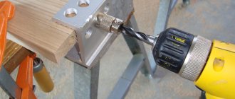
When working with an angle grinder and drilling, you must wear glasses - they will protect your eyes from metal shavings. In general, when working with any tool, you should follow safety rules and use personal protective equipment.
Video works Electric room Interskol
The parts are connected together in such a way that the bed in which the tool is fixed during operation has protrusions and recesses due to its shape.
To accurately determine the configuration of the rack components, you must first make a template from a poster plate that will fit snugly on the body planner, and then cut it from half of the rack, adjust the Edge cutting tool, which is attached to an electric drill.
The remaining parts are fixed together with screws and duralumin corners and screwed onto the substrate.
The height of the stand is selected by calculation, so the center of gravity should be as low as possible, so the structure will be more stable. The distance between the tool body and its base is 20mm, and to ensure that the posts do not become detached, they can be fixed with a metal bracket.
We recommend that you familiarize yourself with
- A set of power tools for wall repair. Power tools always need repairs on walls or hanging shelves, images.
When working on a wall surface, you need a range of power tools that every home should have.
Airplane: the invention continues. Making airplanes is quite simple. The shoes consist of three parts of oak. The midsection of the shoe is 1.5mm wider than the gland to allow for lateral adjustment. On it, at the desired angle, Garden Tools presents a new brand - luxury garden and parking tools Manor of the British company - manufacturer of hand tools RemoColor Tools Limited.
The yard tool is beneficial. Simple grinding system. At the first stage of tool grinding, the grinding wheel usually has a profile groove (Fig.
1). On the second, the edge of the blade is sharpened and filled. Leftovers and decks. In rotation
Universal tongue and groove Shpuntubel is a carpentry tool that brings a narrow rectangular groove - a handle on the edge or on plates, processed construction furniture Data at some distance from its edge. In progress
Do-it-yourself thickness planer made from an electric planer
It is precisely this approach to solving most tasks for a surface planer that arise in a home workshop that we find most interesting.
First of all, this interest is based on minimal modifications to an existing tool to perform the work of expensive equipment with almost the same result.
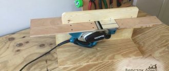
By installing an electric planer on a platform with variable height, we get almost the same thickness planer. True, it is not the position of the work table that is regulated, but the position of the working tool in relation to the workpiece being processed, but this does not change the essence of the process. The role of the table here is played by a flat, powerful board with width limiters on the sides. They also serve as the mounting location for the main unit. But first, let's talk about him.
On the planer, we will replace the rear support plate with a homemade one made from OSB or plywood, with a thickness that ensures the same level as the front plate, which regulates the required gap (1 - 3 mm) for removing chips. Its width should correspond to the width of our improvised desktop.
On the sides of this plate, slats are screwed to attach the legs, the height of which is dictated solely by common sense. It is obvious that, based on the standard width of the plane knives of 82 mm, the thickness of the workpieces being processed should not be more than 100 mm, so the distance between the axes of the leg fastenings can be taken as 110 - 120 mm. Accordingly, their total length will range from 140 to 160 mm with a width of 35 mm and a thickness of at least 10 mm. The legs are fastened strictly at the same distance from the edge of the bar.
Installation of the assembled movable upper unit with an electric planer on the desktop is carried out locally, so that the fastening is strictly at the same level. This is done to ensure that its movement is parallel with respect to the base surface, which will ensure accurate processing of the workpiece.
The easiest way to set the height during work is by selecting slats of appropriate thickness, screwed onto the work table width limiters, or using other stands.
And the clamping of the working tool is ensured with spring ties or a harness, but for small workpieces this is not required at all. Also, in a given position, this parallel platform can be fixed with self-tapping screws.
Video of using a surface planer assembled by yourself:
The process of assembling a circular saw table
First, adjust the base to the optimal size. The wooden countertop is treated and left to soak in the antiseptic composition for a day. The metal base is sanded along the edges to avoid nicks.
Wood antiseptic is a modern building material that protects wood of any species in structures.
Electric saw
Electric saw table assembly process:
- First, prepare the beams, which are trimmed using a plane. A strong frame is assembled from them. Holes with a diameter of 5 mm should be drilled on each side of the base.
- Holes of the same diameter are also made in the drawers.
- Legs and drawers are installed on the tabletop. To ensure fixation, it is recommended to use clamps. They will help secure the legs while the glue dries. They are additionally fixed with metal corners and tightened with self-tapping screws.
- Fastening the saw with M4 bolts. The process is performed from the reverse side.
- To make a parallel stop, two strips are sawn off from plywood. Their width should be similar to the width of the tabletop. The average size is 10 cm. The corners must be rounded and polished.
The key property of the created table should be convenience
Important! When installing an electric saw, you need to fix the start button
For this purpose, a wire is suitable, which is threaded through the hole in the handle and twisted in the desired position.
Hand saw
For a hand saw you will need a 20mm sheet of plywood. The tabletop blank is made according to the selected size. The markings are made with a pencil, and the cutting is done with an electric jigsaw. Finally, the edge is milled. The workpiece must be sanded with sandpaper.
Care should be taken to ensure its stability. No loosening is allowed, otherwise it will negatively affect safety.
Subsequent assembly technology:
- The header is turned over, and markings are made on the bottom side for a hand saw. You need to attach a saw without a disc to the base and mark the dimensions of the sole.
- Using a hand router, a 10 mm recess is made.
- Next, the saw is tried on and the markings are adjusted.
- Markings are made on the bottom side, which are intended for stiffening ribs. For them, blanks are prepared from boards measuring 50x100 mm. The optimal location is up to 10 cm from the edge of the table.
- The longitudinal stiffening ribs are sawn and attached to the tabletop using wood glue. Clamps are used for fixation. Using a similar principle, side stiffening ribs are attached from beams.
- After the glue has dried, holes are drilled in the stiffeners and tightened with self-tapping screws.
- For table legs, boards measuring 50x100mm are used. The average optimal height is up to 110 cm. The legs are attached to the outside of the stiffeners with strong bolts. To improve stability, you can use ties made of beams measuring 50x50 mm.
The tabletop should have as smooth a surface as possible. This will reduce the likelihood of injury while working. The hand-held circular saw is installed in the finished groove from the bottom side, the sole is fixed with bolts. A toothed disk is inserted into the slot. By following the technology and completing all the steps, you can make a homemade table at minimal cost to suit your height.
Regularly check the position of the table and its strength. The structure must be stable, without loosening.
Additional Assembly Tips
The metal for the stove is cut with a grinder or jigsaw. To cut a groove, it is convenient to use an electric jigsaw, having previously drilled a hole for its file in the slab, or an electric drill with an appropriate attachment. The edges of the slot are processed with a file so as not to get injured by them later.
You can secure the metal base plate with flat head screws (so that they do not interfere with work) or by welding it. The first option is preferable because, if necessary, the electric plane is easy to disassemble.
Before installing the drum, it is recommended to check the sharpness of its knives. If it is bad, then it is better to sharpen the blades immediately, using, for example, a regular whetstone. It is necessary to constantly ensure that the cutting attachments are well secured without distortion.
The basis for making your own knives are steel plates or hacksaw blades for metal, sharpened at an angle of 30 degrees.
The sequence of making an electric plane from a grinder with the working drum placed in a vertical position is demonstrated in the videos below. It also shows possible errors when assembling a homemade product.
https://youtube.com/watch?v=SY6xchF8VzU
Another option for creating a homemade electric planer from an old, non-working model is shown step by step in the video below.
Using the made power tool, you can process boards, beams and other workpieces. An electric planer assembled with your own hands must be used in compliance with safety requirements. The parts must be fed correctly to avoid getting your fingers caught in the drum.
There are many options for homemade electric planes. They have varying degrees of complexity, as well as different functionality. In this regard, the limitations are mainly related to the technical thinking of the inventors and the parts and materials available “at hand”. If necessary, the manufactured equipment can also be equipped with automation equipment.
Assembling a jointing machine based on a jigsaw
A jointer is designed to remove existing irregularities from the surface of wood. The work process consists of one-sided planing of lumber along a plane. You can also shoot at different bevel angles. Thanks to processing on this equipment, beams or boards become smooth.
The design of the jointing unit is simpler than that of its thicknesser counterpart. This allows you to assemble the installation yourself using available materials.
The procedure for making a jointer
To make a planer for processing small-sized workpieces, you will need an electric plane that can be fixed in a stationary position. The base of the created unit can be a fragment of plywood, MDF or chipboard. A piece measuring 50 by 35 cm is sufficient. The thickness of the sheet material used should be more than 2 cm.
Assemble the jointing tool by performing the steps in the following sequence:
- cut out the base for the machine from the existing sheet material;
- a stop for the workpiece is attached to it using self-tapping screws or screws at an angle strictly of ninety degrees (a square is used to set it);
- install ribs that will ensure rigidity of the stop;
- An electric plane is attached to the base using M8 bolts and nuts.
If you need to plan large workpieces, then it is enough to increase the size of the unit being created. This will result in a design as in the photographs below.
In addition to the considered option from an electric planer, jointing equipment can be assembled in another design. The practical implementation of such designs depends on the materials and creativity available to the home craftsman. How to make homemade jointing units of other designs is shown in the following videos:
DIY thicknesser machine
The need to make a thicknessing machine with your own hands often arises in a situation where the use of conventional planing is clearly not enough to obtain a smooth surface for the future floor or parquet. It will not be possible to use an electric planer; the quality of the surface after an electric planer will probably be quite high, but it will obviously not be possible to get rid of the stripes that appear on the surface of the wood with each pass.
There is only one way out - try to make a thickness planer using an electric planer according to the drawings with your own hands. Thanks to the powerful bed and guide rails, the surface of the wood after processing the board with a thicknesser will be relatively uniform and flat.
Thicknesser from an electric planer
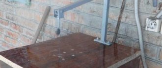
To build a full-fledged thickness planer, you first need to make a frame or table on which the tool will be mounted. The electric planer is equipped with a powerful commutator motor, which can easily cause injury, so the fastening of the homemade surface planer to the table must be strong and reliable.
The second step is to select a plan for the layout of the surface planer. The simplest version of the device is shown in the drawing and photo.
In fact, it is necessary to make a movable platform on which the electric planer itself will be mounted. The lifting height of the tool sole on the surface being processed is adjusted using four screw-nut pairs installed on the sides of the device.
The main difficulty in operating an electric planer is correctly adjusting the lifting height of the cutting edge. In normal mode, the extension of the knife above the plane of the sole is adjusted by a screw spring-loaded handle. The amount of overhang is usually checked visually or by hand, whereas when working in the thicknesser mode, you will have to be guided only by the readings of the scale on the handle.
The only disadvantages of a planer of this type will be the small width of the surface being processed, 90-100 mm, and the actual loss of the electric planer as a hand tool. It is clearly inconvenient to disassemble and reassemble a thickness planer every time you need to remove a couple of millimeters from a nailed board.
Homemade woodworking thickness planer
Often, when carrying out carpentry work, there is a need to use a thicknesser to run a board or a board glued together from slats with a width of more than 100 mm. Planks and panels made of wood 100-140 mm can still be somewhat leveled with an ordinary hand-held electric planer, provided that the material is securely fixed on the workbench. True, it is necessary to plan diagonally in several passes, followed by processing with a manual grinder.
Cross planing of wide boards can still be used for one or two boards, but if we are talking about two dozen boards or boards, then you obviously can’t do without a homemade thickness planer.
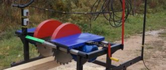
The simplest version of a surface planer is shown in the diagram.
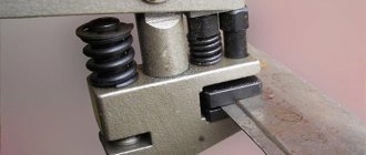
The basis of the design is a massive steel frame welded from angle steel. An asynchronous motor with a power of 1.5-1.8 kW and a speed of at least 1200 rpm is installed in the lower part of the frame of the thicknessing machine. The motor must be mounted on a spring-loaded cushion to ensure tension on the machine drive belt and reduce vibration on the thicknessing knives.
The second most important element is a cylindrical block with slots for knives and bearing supports. You will have to buy this thicknesser part ready-made; making it yourself is almost impossible
The drum with bearings is installed directly on the machine bed after mounting the work table.
At the last stage, two pulleys are selected for the belt drive; the ratio of the diameters of the pulley groove should be in the range of 2.5-2.8. A pulley of larger diameter is mounted on the motor shaft, and a smaller one is mounted on the drum shaft. The rotation speed under load should not exceed 4 thousand rpm.
Making a homemade jointing machine
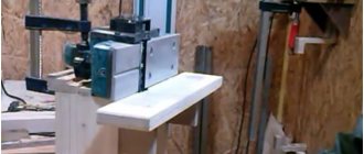
Side wall
First of all, we will make a side wall, for this we use plywood 18-20mm thick with dimensions 150x480mm. By cutting out a place in the workpiece in which the electric planer will be fixed. This should be done using an electric or manual jigsaw, since the sample shape has a complex configuration.
Using a drilling machine, two grooves should be made in the side panel at a distance of 70 mm, with their help, in the future, the base of the front table will be attached.
Machine base
We make the base. This is a simple rectangle that needs to be cut on a circular saw or other sawing machine from the same plywood 18-20mm thick with dimensions 180x480mm. Everything is simple here - we connect the base and side wall at an angle of 90 degrees with self-tapping screws into the end of the wall.
In the future, the plane will be installed as follows.
Back table
The back table is also made of 18-20mm plywood with dimensions of 150x600mm; a technological opening is cut out to get this shape.
The end edge of the opening must be cut at an angle. This can be done on a circular saw or jigsaw.
Next, unscrewing 4 screws, remove the fixed “sole” from the electric planer and mark the table of the future machine.
Having drilled the necessary technological holes, they need to be countersunk a little so that the standard screws are recessed “flush” and do not interfere with the movement of the workpiece.
We install our homemade back table in place of the removed sole of the electric planer using standard screws. After this, you need to fix this table on the side wall with self-tapping screws into the end of this wall.
Front movable table
The front table, which must be adjustable in height, is made of two rectangular pieces fastened at an angle of 90 degrees. For greater structural strength, you need to make triangular stops between them. In this example, everything is attached with self-tapping screws; however, for greater strength, it is recommended to coat the joints with wood glue. The end result should be a design like this.
At a distance of 70 mm from each other, you need to make two through holes with a diameter of 8-10 mm and hammer furniture drive nuts into them. It is better to do this before assembling the base.
Installation of the movable table is done using two screws on the back of the side wall. For convenience, you can use bandages with a winged head or make homemade holder mounts. The installation should be carried out so that the plane of the moving part of the “sole” of the electric planer is in the same plane as the movable table of the jointer.
Side stop
The side stop is needed to ensure smooth and parallel movement of the workpiece, as well as to establish an exact 90-degree angle between the work table and the stop plane. The stop is made simply - from two parts, which can be made from either plywood or solid wood. In this case, an array is used.
Two rectangular blanks are fastened at an angle of 90 degrees, forming a “corner”. After which it is rigidly attached to the stationary part of the table.
A do-it-yourself jointing machine made from an electric planer is ready for use.
main idea
Yes, such a homemade jointing machine, unlike serious industrial designs, has a number of disadvantages, namely:
- Cannot boast of high processing accuracy;
- The width of the workpiece is very small - only 110 mm;
- Lightweight is a disadvantage, since a heavy massive base always gives the device stability and, as a result, ease of use, which ultimately improves the quality of the result.
- Low power, limited by the power of a household electric planer;
- The body material is wood, that is, not durable;
However, it also has undeniable advantages that make it very useful for achieving certain goals and performing a number of tasks, since it has the following advantages:
- Low cost - serious jointing machines cost tens and hundreds of thousands of rubles, and the cost of this homemade jointing machine consists of the cost of the plane and materials;
- Compact and portable - it can easily be stored anywhere in the workshop and can be deployed for work in a matter of minutes.
- The simplicity of the design affects its reliability and maintainability.
- The ability to make the necessary dimensions of the machine “to suit you”, for example, you can increase the length of the work table or change the height.
Additional Assembly Tips
The metal for the stove is cut with a grinder or jigsaw. To cut a groove, it is convenient to use an electric jigsaw, having previously drilled a hole for its file in the slab, or an electric drill with an appropriate attachment. The edges of the slot are processed with a file so as not to get injured by them later.
You can secure the metal base plate with flat head screws (so that they do not interfere with work) or by welding it. The first option is preferable because, if necessary, the electric plane is easy to disassemble.
Before installing the drum, it is recommended to check the sharpness of its knives. If it is bad, then it is better to sharpen the blades immediately, using, for example, a regular whetstone. It is necessary to constantly ensure that the cutting attachments are well secured without distortion.
The basis for making your own knives are steel plates or hacksaw blades for metal, sharpened at an angle of 30 degrees.
Hacksaw blade
The sequence of making an electric plane from a grinder with the working drum placed in a vertical position is demonstrated in the videos below. It also shows possible errors when assembling a homemade product.
Another option for creating a homemade electric planer from an old, non-working model is shown step by step in the video below.
Using the made power tool, you can process boards, beams and other workpieces. An electric planer assembled with your own hands must be used in compliance with safety requirements. The parts must be fed correctly to avoid getting your fingers caught in the drum.
There are many options for homemade electric planes. They have varying degrees of complexity, as well as different functionality. In this regard, the limitations are mainly related to the technical thinking of the inventors and the parts and materials available “at hand”. If necessary, the manufactured equipment can also be equipped with automation equipment.
additional information
All the tools listed above are standardized products. Therefore, in order for them to perform their job correctly and accurately, they must be manufactured in accordance with the requirements of GOST 15987-91. Below are extracts from GOST that define the basic requirements.
DIY planer drawings
List of required materials from which you should make a hand plane with your own hands:
- ash;
- beech;
- maple;
- hornbeam;
- white acacia;
- birch (allowed).
The wood must be well dried, without knots, cracks or rot. To glue parts, you must use waterproof glue.
Requirements for the metal used
Knives are made from the following types of double-layer steel:
- the main layer is made from grade 30, GOST 1050 (U8, U8A, U9 are allowed, GOST 1435);
- cladding layer - from grades 9ХФ, 9Х5ВФ, Х6ВФ, 9ХС, GOST 5950.
It is allowed to use metal of other grades, but no worse than those given in the standard. Knives must be perfectly sharpened and have an appropriate sharpening angle.
Advice: in order for the processed surface to be of decent quality as a result of the work of the tool, it is advisable to have a device in the workshop for sharpening a plane with your own hands.
How to extend the life of an electric planer
An electric plane is one of the main tools for woodworking. Properly configured, it is an indispensable assistant in the hands of a carpenter. If, over time, the tool settings have gone wrong, or you don’t know how to prepare the electric planer for work, then it is advisable to get specialized advice, which we are ready to offer in this material. Otherwise, all the work when working with an unregulated plane will go down the drain, and there will be little pleasure from such miserable work.
Like any tool, the plane must be properly adjusted before work. And an electric plane imposes even more stringent adjustment requirements than hand tools. Therefore, the following steps should be carried out before each work with such equipment.
The only warning before inspecting the tool is to follow the safety tips. So the cutting parts of the plane must be treated very carefully. After all, due to the fact that the cutters of this tool are extremely sharp, you can cut yourself on them even when the equipment is turned off, not to mention when the equipment is running. Otherwise, such equipment should be treated like any other power tool.
Required materials and tools
Let's consider the manufacture of the simplest design, designed for a planing depth of up to 1.2 mm and a width of processed wooden workpieces of up to 120 mm. To assemble such an electric plane with your own hands, you will need the following materials and parts:
- bearings;
- steel strips;
- pressure plates;
- M6 and M8 screws with nuts;
- spring washers;
- metal corners (20x20x3 mm);
- staples;
- sheet of plywood (10 mm) or metal (3-5 mm thick);
- belt drive pulleys installed on the shaft of the electric motor and drum;
- a drum (with one or two knives) from an old planer or electric planer, on which you can change cutting attachments;
- a working electric motor from a grinder, an old electric plane or a planer;
- belt;
- button (switch) to turn the electric planer on and off;
- wires and cord with plug;
- residual current device (RCD);
- capacitors (if the electric motor used is three-phase).
Installing a separate RCD for an electric plane in the panel (even directly on the machine) will increase electrical safety when working with equipment. Protection is selected according to the power of the working engine. The cord and wires must be of a suitable cross-section, taking into account the power of the installed electric motor.
Phase shifting capacitors must be connected in parallel. In this case, the required total capacity is determined by the power of the installed electric motor: approximately 100 μF per 1 kW. Capacitors must be designed for mains voltage.
To implement the project you will need the following tools:
- several wrenches designed to tighten the nuts on the bolts;
- roulette;
- building level;
- marker or pencil;
- welding machine with electrodes;
- an electric drill with drills and a circle of small diameter intended for cutting;
- a jigsaw with files for it for wood and metal or hand saws for a similar purpose;
- angle grinder complete with wheels for cutting metal.
- https://verstakdoma.ru/stati/instrument/samodelny/rubanok-svoimi-rukami/
- https://tehnika.expert/dlya-remonta/elektrorubanok/delaem-instrument-svoimi-rukami.html
- https://drevogid.com/instrumenty/ruchnoj-rubanok.html
- https://zdesinstrument.ru/ruchnoj-rubanok/
- https://stankiexpert.ru/ehlektroinstrument/rubanok-ruchnojj.html
Classification and device
There are manual and stationary electric jointers. The first can be used when processing boards that are relatively short in length. Such an electric jointer must be equipped with a mounting unit, thanks to which it can be securely installed on an existing workbench. Stationary versions are typical for carpentry and furniture workshops.
The design of a jointer - manual or stationary - is the same: an electric motor, through a reduction gearbox, transmits torque to the working element - a knife drum, equipped with removable blades. Rotating, the tool head receives a vertical feed. The kit usually includes several types of knives that are designed for processing wood with different hardnesses. Thus, an electric jointer differs from a mechanical one in that surface treatment occurs as a result of rotational rather than reciprocating movement of the working part of the tool. The number of knives in different models can be from one to three.
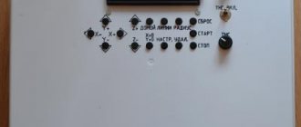
An important element that guarantees the safety of working on a manual jointer is the unit control system. The housing contains two control buttons: only when they are pressed simultaneously does the electric motor start. There are also:
- A socket for connecting a vacuum cleaner, with which you can remove accumulated chips. For most models, the bell is located on the right side of the body, although there are also versions where the direction of chip ejection can be changed.
- Resistant handle.
- Control buttons.
- The manual screw is a planing depth regulator.
- Side stop, with the help of which the working width of the surface being treated is changed.
- Protective folding cover.
- The sole is made of polished thick sheet aluminum.
- A battery connector where you can connect a regular 18 V battery. Naturally, there is a two-meter long cable to connect the engine to a household network.
A budget option for a homemade surface planer
This is the simplest method of using an electric planer as a surface planer. Of course, it would hardly occur to anyone to call this design a thickness planer, but in terms of the function it performs, this is exactly what it is.
We deliberately selected an option for wide blanks. Indeed, in this form it performs work that most industrial thicknessing machines cannot do precisely because of the width of the material being processed, and in our case it is limited only by the length of your hands.
Of course, we cannot recommend such a barbaric attachment of an electric plane - a rather expensive tool - to a moving platform. Much more interesting is the option of securing it, described in the previous section of the article, but using a wider platform and moving the slats along the width, and not along the axis of the tool
In this case, the danger of damaging anything important inside the plane body is reduced to zero.
In the example given, a glued assembly of wooden slats of various sizes and even types of wood is processed.
Height adjustment is made by installing calibrated bars on the sides of the work table, two sets of which will allow you to process an unlimited number of workpieces on both sides to a given thickness.
Planer device
During the evolution of the plane, quite a lot of its varieties have appeared, which can not only process the planes of wood, but also be used for figured cutting. To enjoy manual labor, you need to be able to choose the right plane, and then you will get real works of art from an ordinary piece of wood.
Modern planes can be divided into wooden and metal models. Each of them has its own advantages and disadvantages, but in terms of design, the instruments are similar, like twin brothers.
A standard plane consists of the following parts:
- sole, also known as body;
- cutter;
- wedge;
- slot for chip exit;
- cutter clamp;
- cutting depth regulator;
- horn - front handle;
- emphasis - rear handle.
The key element of the design is the cutter - this is a cutting tool made in the form of a pointed plate.
The blade is positioned at a given angle to the surface being processed. Thanks to the regulator, the knife extends to a certain distance, which allows you to finely adjust the depth of cut and the thickness of chip removal. In factory models, the blade sharpening angle is standard, but professional carpenters change it depending on the type of wood being processed.
The handles also play a certain role. The front one, called the horn, performs a guiding function and usually has a curved shape that provides a better grip on the hand. The rear one is a stop, thanks to which the force necessary for work is created.
With the sole, which can be wooden or metal, everything is not so simple. The main criterion for this structural element is a perfectly flat surface.
If this requirement is not met, it will be difficult to use a hand plane, and you can simply forget about planing accuracy. Taking these nuances into account, a metal sole looks preferable: it is made according to a template, so a priori it has the correct geometry. However, mistakes made by the manufacturer during casting reduce these advantages to zero. Moreover, the metal is susceptible to corrosive changes.
A wooden sole is lighter, and if deformed, you can straighten it yourself, breathing a second life into the plane. However, wood is not a durable material; it is subject to mechanical wear and loses its original properties when exposed to moisture or high temperatures for a long time.
Despite the standard design, there are more than 10 types of planes, and each tool performs a specific function when processing parts. Let's take a closer look at these products.
Types of planes
A plane is a hand-held tool for working wood, allowing you to bring the surface of a product with your own hands to the required quality and size. Having the entire set of types of this tool, you can not only process the surface, but also make various carpentry crafts.
The planer has a whole arsenal of types:
- sherhebel;
- jointer;
- semi-jointer;
- mole cricket;
- sander;
- tzinubel;
- end;
- single;
- double.
- zenzubel;
- federgubel;
- folding belt;
- stabgobel or stabgaltel;
- tongue and groove;
- mold;
- primer;
- humpback
Having a full set of hand tools, if desired, you can make works of wood of any complexity. At the same time, an important factor for successful work is sharpening planer knives with your own hands, which is an expensive production service.
Among the figured planes, the zenzubel stands out with its useful features. It is used for making grooves, quarters, stripping and bringing tenons and cuts to the desired size. The manufacture of this type of instrument will be discussed.
The article outlines an algorithm for how to make a plane with your own hands.
Machine parts
A homemade jointer is represented by a combination of various units that are connected together. The manufacture of the jointer must be carried out taking into account the information below:
- Base. It is represented by the lower part, on which various nodes are based.
- Side wall. It acts as a load-bearing element to which various components are attached for mounting.
- The table is rear or fixed. This element is attached to the side wall and forms the plane of movement of the workpiece.
- Front table. Often this element can change its height. A special mechanism is created for this.
- Side support. It is mounted on the back table; its main purpose is to direct the movement of the workpiece.
- Spacer corners. They are used to strengthen the structure and increase its stability.
- Electric planer. An electric planer is used as a basis in the manufacture of the structure.
This mechanism is characterized by a fairly simple design. To connect individual units, various fasteners are used.
Back table
Making a table for an electric planer with your own hands. A material with a thickness of about 20 mm is suitable as a base. The back table is created according to the instructions below:
- A technological opening is made to obtain a special shape.
- The end edge is cut at an angle. A circular saw is used for this.
- After creating the technological hole, it needs to be countersunk. Due to this, the screws will be deeply recessed and will not interfere with the movement of the workpiece.
- The table is attached to the place of the previously removed sole.
Installation can be carried out using an electric drill or screwdriver, which greatly simplifies the task.
Manufacturing algorithm
To assemble the device with your own hands, adhere to the established plan. The sequence of actions looks like this:
- To create a support, a rectangle is cut out of metal. Markings are made on it for the drum and mounting holes;
- Steel corners are screwed in on all sides of the slab with bolts and then welded;
- From the remaining corners, cut out 4 legs for the plane;
- The resulting racks are welded to the corners of the slab;
- A rack for the motor is assembled from steel strips. It is attached through holes in the support;
- The seams are being cleaned;
- The plate is removed;
- The upper parts of the corners are welded so that there is no space between them;
- The resulting seams are cleaned with a grinder or file;
- The stove is put in place;
- Under the slot, a drum and bearings are placed on clamps or brackets;
- The engine is secured in the desired position (the shaft must protrude);
- Pulleys are installed on the shaft and drum;
- A belt drive is installed;
- The engine is installed in such a way that the belt tension is sufficient;
- A plywood or tin casing is created. It is attached with screws to the corners so as to cover the belt and motor;
- The case is covered with plywood at the location where the start button is installed, then the button itself is installed;
- A capacitor is installed if necessary;
- Assembling an electrical circuit with your own hands (power cable, button, machine, capacitors);
- The first test run of the device takes place.
After starting work, the master pays attention to the direction of rotation of the drum. It should be carried out in the same direction from which the wooden blanks for planing are fed