Welding pipes with high (radio) frequency currents
Welding with high frequency currents (HFC) up to 500 kHz is used for the production of pipes with a diameter of 6–529 mm with a wall thickness of 0.5–10 mm.
The main advantages of this method:
- the possibility of significantly increasing the welding speed of pipes (up to 120 m/min) from carbon and alloy steels, non-ferrous metals;
- obtaining pipes with a high-quality seam from hot-rolled unetched tape, a significant reduction in energy consumption per ton of finished pipes;
- welding pipes made of different metals using one welding equipment.
This made it expedient to transfer a large number of existing pipe electric welding mills to welding with high frequency currents. Most of the newly commissioned pipe welding plants have high-frequency welding equipment.
The use of current with a frequency of 450–500 kHz for welding pipes is based on the fact that the current at this frequency follows the path not of the least ohmic resistance, but of the least inductive resistance. To increase the inductance of the workpiece perimeter circuit in order to concentrate the current at the edges of the workpiece, a ferromagnetic (ferrite) core is introduced into the workpiece.
In radiofrequency pipe welding, the electric current passing along the edges of the pipe workpiece is concentrated directly on the surfaces being joined due to the proximity effect and the surface effect. As the current frequency increases, the proximity effect and the surface effect intensify, as a result of which the maximum current concentration is achieved at the edges of the pipe blank. Welding pipes with radio frequency currents is characterized by a high degree of energy concentration when heating the metal, which occurs in tenths or even hundredths of a second.
High frequency current is supplied to the edges of the pipe workpiece in two ways: contact and induction. In Fig. Figure 1 shows circuits with contact (a) and inductive (b) high-frequency current supply.
Rice. 1. Scheme of high-frequency current supply to the edges of the pipe blank: a - contact; b - induction: 1 - welded pipe; 2 - molded blank; 3 - welding rolls; 4 - inductor; 5 - sliding contact; 6 - welding place
During high-frequency welding with the contact method of supplying the high-frequency current, flowing along a path parallel to the edges of the pipe workpiece, heats them up to the welding temperature. Seam compression rollers compress and connect (weld) the edges together in a plastic state. However, when welding pipes with a diameter of less than 20–25 mm, less resistance may be in the current path along the perimeter of the pipe, rather than along the edges. In this case, to ensure the passage of current along the edges of the welded workpiece, a magnetic core (ferrite rod) is placed inside the welding zone, increasing the inductive resistance along the perimeter of the pipe.
With the induction method of energy transfer, welding of the workpiece is carried out using a ring or slot inductor. The current induced in the workpiece, passing along the perimeter, reaches its maximum concentration at the edges being welded. To enhance the heating effect, a magnetic core made of ferrite rings is usually introduced into the pipe. The choice of current frequency for welding depends on the thickness of the pipe wall, the quality of edge preparation, etc. For example, for TESA 10-76 mills, the optimal frequency is 440 kHz; with increasing pipe wall thickness, the frequency of the welding current is reduced.
Transferring energy to the edges of the workpiece being welded through sliding contacts is a more efficient method compared to induction for medium and large diameter pipes. At similar welding speeds, the power consumption with the induction method of energy supply is twice as high as with the contact method. With an increase in the diameter and wall thickness of the pipes being welded, the power required for induction welding increases even more (by about 40–50%), while the influence of changes in wall thickness is most significant. For pipes with a diameter greater than 200 mm, the induction welding method is usually not used due to a significant reduction in efficiency.
Heating the edges of the pipe workpiece with HDTV allows welding to be carried out both with and without melting of the edges; In this case, three edge heating modes are known:
- the temperature of the edges of the workpiece being welded is lower than the melting temperature of the metal; the pressure on the edges in the welding rolls must be sufficient to cause significant deformation of the edges, destruction and removal of the oxide film from the weld;
- the temperature of the edges of the workpiece being welded at the point of their convergence reaches the melting temperature of the metal; when compressing the edges in seam-compressing rolls, liquid metal with oxides is removed (squeezed out);
- the temperature of the edges up to the point of their convergence reaches the melting temperature of the metal, and at the junction the edges are additionally heated; Subsequently, when the edges converge, an intense release of melted metal occurs with the destruction of oxides and their removal from the weld zone.
The choice of one or another welding process mode depends on the properties of the pipe metal, the quality of the workpiece surface and the requirements for the internal flash. If there are dense refractory oxides on the surface of the metal, for example in stainless steels, then the third welding mode is most effective for removing them from the weld zone.
Low-carbon steels weld well under all conditions. However, in the first mode, the pressure on the welded edges must be greater than in fusion welding, which causes the formation of an even, but significant internal flash. With a pipe wall thickness of 1.5–2.0 mm, the burr height reaches 0.8–1.0 mm. Therefore, it is advisable to carry out the process with melting at the point of convergence of the edges.
The pressure created by the welding rolls is much lower in this case, and the size of the flash does not exceed 0.25–0.3 mm. The quality of the welded joint depends on the welding speed; as it increases, the heating time and the width of the heating zone of the edges are reduced, as well as the period of intense metal oxidation, which leads to improved welding quality and a reduction in internal burr.
Changing the angle of convergence of the edges (the distance between them) significantly affects the electrical parameters of welding. As the angle of convergence of the edges decreases and the distance between them decreases, the heating intensity increases, which makes it possible to increase the welding speed. In most installations, current is supplied to the edges using rotating disks, the durability of which is much higher than that of sliding disks.
One of the main disadvantages of pipes produced by high-frequency welding is the relatively large internal bead (up to 60% of the wall thickness). In addition, when producing small-diameter pipes, it is practically impossible to install a magnetic core to increase the inductive reactance along the perimeter of the pipe.
Species and groups
High-frequency welding, depending on the method of transferring energy to the edges, is classified into types:
- Contact . Contacts are placed on the welded edges, to which high-frequency current is supplied.
- Induction . Heating occurs using an inductor, when alternating current flows through it, a magnetic field is generated. When a metal part is placed in the middle of the inductor, an alternating magnetic flux will cause an induction current and heat will be generated in a given area.
HDTV welding processes are divided into 3 groups:
- Pressure with reflow . The mechanism consists in preheating the joined surfaces and their local melting. The molten material is removed from the welding zone during upsetting. A seam is formed between parts in a solid state.
- Pressure without melting . The surfaces to be welded are preheated to a temperature below the melting point of the metal being processed.
- Melting without pressure . The elements are heated until they melt. The weld pool of metal solidifies and a seam is formed without applying pressure.
Induction welding of pipes
Induction welding of pipes is used for the production of water, gas and structural pipes with a diameter of 21.5 to 219 mm.
A schematic diagram of induction welding of pipes is shown in Fig. 2. The edges of the pipe blank, formed from a rolled tape, move under the inductor, gradually heat up and, at welding temperature, are compressed by seam-compressing rollers. For heating, a flat inductor with a magnetic core is used.
The magnetic flux created by the inductor current crosses the pipe blank perpendicular to its surface. The induced current is concentrated under the inductor, flows along the edges, heating them to the welding temperature. Energy is supplied to the pipe blank in a non-contact manner. This makes it possible to produce pipes from hot-rolled strip without special edge processing.
Rice. 2. Schematic diagram of induction welding of pipes: 1 - formed workpiece; 2 - linear inductor with magnetic cores; 3 - welding rolls
Depending on the wall thickness and mill productivity, heating of the edges of the pipe blank is carried out by one or two inductors. The frequency of the welding current is determined depending on the workpiece material used and the wall thickness and must ensure the penetration of the current through the entire thickness of the edge of the pipe workpiece.
One of the most important parameters of the pipe induction welding process, which affects the formation of the seam and its structure, is the heating temperature of the edges: with increasing temperature, the required upsetting pressure decreases.
Research has established that at temperatures of 1380–1420 °C, iron oxides on the edges of the pipe workpiece are in a liquid state and, when upset, easily extend beyond the main section of the welded edges. A large temperature gradient between the heated and cold sections of the pipe blank creates conditions for preferential plastic deformation of the heated edges directly in the joint and near-butt zone, which ensures the production of a high-quality welded joint. The pressure should be in the range from 34.3 to 88.0 MPa, and the amount of settlement should be 0.7–1.3 of the wall thickness of the pipes being welded.
Heating of the edges of the pipe blank during induction welding is carried out over a relatively large distance. The distance from the last stand with the split washer of the forming mill to the welding gauge reaches 3 m, as a result of which the mills are sensitive to the settings and quality of the strip. This often leads to a change in temperature and its distribution at the edges along the length of the strip during welding, which greatly affects the quality of the seam.
An increase in the heating temperature of the edges reduces the resistance to upset of the edges of the pipe blank, which reduces the pressure on the edges and causes a decrease in the strength of the seam.
Reducing the heating temperature increases the pressure on the edges, which promotes good compression of the edges, however, the low temperature does not provide proper weldability due to the presence of unmelted oxides on the edges.
Adjusting the force of edge upset by seam-compressing rolls during mill operation reduces the stability of the quality of the weld and complicates the work of the welder, therefore it is necessary to heat the edges at a constant temperature, which is possible thanks to the installation of an automatic temperature control system on the mills.
To obtain high-quality welding, it is enough to heat each edge of the pipe blank to a welding temperature to a width of 0.5–1.3 of the wall thickness. The heating zone depends on the width of the induction wire of the inductor and the heating time. The gap between the edges under the inductor should be minimal. The best heating conditions are provided when the edges are tightly compressed; in this case, the volumes of heated metal on each of the edges are maximum and the highest temperature will be directly on them.
When induction welding of all sizes of pipes made of low-carbon steels, a high-quality seam can be obtained using the following mode:
- heating temperature of the edges of the pipe blank 1380–1450 °C;
- the amount of edge settlement is 0.5–1.3 of the pipe wall thickness;
- settlement pressure 39–88 MPa.
The amount of power consumed by the welding device is greatly influenced by the size of the gap between the inductor and the edges of the pipe workpiece. To reduce the power consumption of the welding device, you need to make this gap as small as possible.
Advantages of the induction welding method:
- use of hot-rolled strip without preliminary descaling and special treatment of the edge ends;
- production of thin-walled pipes and high welding speed (up to 90 m/min);
- absence of direct contact of current-carrying electrodes with the pipe.
Disadvantages of the induction welding method:
- the impossibility of welding thin-walled pipes with a wall thickness of less than 1.5 mm (this is due to the problem of ensuring the stability of the heated zone of the edges, for which it is necessary to create an inductor with a magnetic core less than 10 mm wide);
- dependence of the stability of the welding process on fluctuations in the gap between the pipe and the inductor, which places increased demands on the dimensional accuracy of the molded workpiece;
- the possibility of metal delamination in the edge area due to the presence of impurities in the form of oxides and sulfides.
Compatible materials
A single dimensional group of PVC showing an asymmetric distribution of atoms with different electronegativity.
A single dimensional group of polyethylene showing a symmetrical distribution of atoms. The mechanism of RF heating relies on a dipole in the molecule to generate heat, and therefore plastics used in RF welding are limited to those whose molecules contain an electric dipole.[5] Permanent molecular dipoles can form due to differences in electronegativity between the atoms of a molecule. Negative charge shifts toward atoms with higher electronegativity, resulting in more negatively charged regions surrounding more electronegative atoms and positively charged regions surrounding less electronegative atoms.[1] Because polyethylene is composed of symmetrical group measures, dipole shapes and polyethylene cannot be joined by radio frequency welding. Like water, polyvinyl chloride (PVC) is composed of asymmetrically arranged atoms with different electronegativity, resulting in a dipole moment. Due to its strong dipole moment (and other properties), PVC is considered an excellent material for high frequency welding. In addition to polarity, properties that contribute to good RF weldability include high dielectric constant, which reduces current resistance; high dielectric strength, preventing the formation of an arc through the connection elements during welding; and high dielectric loss, which is a factor that describes the amount of heat generated by an electric field.[1][2]
Some plastics commonly welded using dielectric heating include:[1][3][6]
- Polyvinyl chloride (PVC)
- Chlorinated polyvinyl chloride (CPVC)
- Polyurethane
- Nylon
- Cellulose acetate
- Ethylene vinyl acetate (EVA)
- Polyvinylidene chloride (PVDC)
- Polyethylene terephthalate (PET)
Additional elements may be added to a joint for a variety of reasons—to improve thermal insulation, prevent parts from sticking to welding equipment, prevent arcing, and buffer uneven clamping pressure or electrical field.[2] Non-polar plastics can be welded using a conductive composite material implant to improve dielectric loss.[1]
Resistance welding of pipes
Resistance welding is used to produce pipes with a diameter of 5 to 529 mm and a wall thickness of 0.4 to 20 mm. Pipe material is carbon and low-alloy steel. For welding steels with a high carbon content and pearlitic alloy steels, special welding and cooling modes are used to prevent hardening of the heat-affected zone.
The welding current is supplied to the edges of the strip by contact method using rotating electrode rings, insulated from each other and connected to the secondary winding of the welding transformer. Electrode rings and seam-compressing rolls of the welding stand create a closed gauge.
In Fig. Figure 3 shows a diagram of electric welding of pipes using the resistance method. Direct or alternating electric current is supplied to the edges of the pipe blank (6) using electrode rings (1), separated from each other by an insulator (2). The edges of the formed pipe blank, falling into the gap between the electrode rings, heat up. Under the pressure of seam-compressing rollers (3) and electrode rings forming a closed welding gauge, the edges of the pipe are welded .
Rice. 3. Scheme of resistance welding of pipes: 1 - rotating electrodes; 2 - insulator; 3 - seam compression rolls; 4 — rolls of the last forming stand; 5 — guide washer (split); 6 - pipe
Under the influence of forces from the compression rollers and electrode rings, the edges of the pipe blank are brought closer together. Through the electrode rings, an electric current with a voltage of several volts and a current intensity reaching tens of thousands of amperes is supplied to the workpiece. The resistance of the joint between the edges of a pipe blank is much greater than the resistance of the solid body of the pipe, therefore, when an electric current passes, the edges heat up to a higher temperature. The application of pressure from the seam-compressing rolls and electrode rings ensures welding of the edges of the workpiece. Most often, alternating welding current is used with a frequency of 50 to 400 Hz (sometimes up to 700 Hz). Welding speed from 30 to 60 (90) m/min.
When welding pipes using the resistance method using alternating current 50–700 Hz, periodic inhomogeneity in the quality of the weld inevitably occurs as a result of a sinusoidal change in the current value. Therefore, to produce pipes with a diameter of 10–20 mm and a thickness of 0.7–1 mm, DC welding is used. Pipes welded by direct current are of high quality and have minimal flash (0.15–0.25 mm in height).
The quality of welding is greatly influenced by the exact coincidence of the junction of the edges with the gap between the electrode rings, which determines the symmetry of heating of the edges of the pipe installation (Fig. 3).
Advantages of resistance welding method:
- a wide range of pipes in terms of wall thickness and diameter;
- simpler and cheaper welding equipment;
- lower specific production costs when producing pipes of increased diameter.
Disadvantages of resistance welding method:
- the need for preliminary preparation of strip edges (cleaning of burrs and scale);
- large burr (up to 0.5 wall thickness);
- wear of the electrode rings, leading to disruption of electrical contact and stability of the welding process;
- limited brand assortment of pipes.
general information
The method involves the use of laws and phenomena of physics.
- proximity effect;
- occurrence of electromagnetic forces;
- surface effect;
- influence on the distribution of current in the conductor of copper screens and magnetic cores;
- coil or ring effect;
- changes in the properties of metals with changes in magnetic field strength and temperature.
In high-frequency heating, the main role is given to the phenomenon of surface effect and proximity effect.
Surface effect
It consists in the uneven distribution of alternating current along the conductor profile (current penetration depth). The current density is highest at the outer surface and gradually decreases as one moves deeper. It is minimal in the center of the body.
Due to the surface effect, energy release is concentrated in the outer layers and the metal is rapidly heated. The proximity effect also contributes to this manifestation.
Proximity effect
It makes itself known by passing alternating current conductors through the system. In this case, each of the conductors is influenced by both its own alternating magnetic field and the field of other conductors.
The smaller the distance separating the conductors from each other and the higher the frequency of the current, the stronger the proximity effect.
This phenomenon contributes to increased energy concentration in the outer layer of the metal subjected to heating. Thus, the release of thermal energy occurs directly in the thickness of the metal, providing rapid heating in the welding zone and high efficiency of the heating method.
Argon-arc pipe welding
Arc welding with arc protection by inert gas (helium or argon) is used to produce pipes with a diameter of 4–426 mm with a wall thickness of 0.2–5.0 mm from high-alloy steels (corrosion-resistant and heat-resistant), as well as from a number of non-ferrous metals ( aluminum, magnesium, etc.) and their alloys. The welding speed of pipes, depending on the material, size of the pipes being welded and the protective atmosphere used, is 0.5–8 m/min.
In inert gas arc welding, an electric arc burns between a non-consumable tungsten electrode and the pipe being welded. A special device is used to supply current and supply inert gas. Welding is carried out using direct current of direct or reverse polarity, depending on the metal of the pipe, as well as alternating current. Pipes made of corrosion-resistant and chromium-iron-nickel steels are welded using direct current of direct polarity (the negative pole is connected to the electrode), and pipes made of aluminum, magnesium and their alloys are welded using current of reverse polarity. Conventional welding generators are used as a power source.
The high thermal conductivity and heat capacity of helium contribute to the creation of conditions in the metal heating zone under which the mechanical properties of the welded pipe are significantly increased and the operating conditions of the tungsten electrode are improved. The disadvantages of using helium include its high consumption due to its low density.
The thermal conductivity and heat capacity of argon is significantly lower than that of helium, and its density is higher. The thermal conductivity of argon is almost equal to the thermal conductivity of air, and the heat capacity is almost half that of air. Therefore, when using argon, the heat affected zone is much larger than when using helium.
The temperature of the electric arc during ADS welding is 5000...8000 °C, current 180...400 A, voltage 20...60 V.
For non-consumable electrodes, tungsten grade VT-15 is used, containing 1.5–2% thorium oxide. The diameter of electrodes dе made of thoriated tungsten is 1–7.5 mm (where dе < 4 mm were used for welding small-diameter pipes, and dе ≥ 4 mm for welding large-diameter pipes).
In Fig. Figure 4 shows one of the main components of the mill - the welding device. The tungsten electrode (1) is clamped in the electric holder (2), to which current is supplied. Shielding gas is supplied through the ceramic nozzle (3) of the burner body (4); The burner body and electric holder are cooled with water. The inert gas flows through the pipe (5) into the chamber (6) above the electric holder and from there through the hole (7) enters the ceramic nozzle (3). Cooling water is supplied through the tube (8) directly to the electric holder and then leaves the burner through the tube (9), while cooling the power cable located in it. Water flow is 0.5 l/min. During welding, the edges of the workpiece (10) are compressed by rollers (11). A special feed mechanism regulates the installation of the torch with the electrode relative to the edges being welded.
Rice. 4. Scheme of argon-arc pipe welding: 1 - electrode; 2 — electric holder; 3 - ceramic nozzle; 4 — burner body; 5 — shielding gas supply pipe; 6 - camera; 7 — gas supply hole; 8, 9 — pipes for supplying and discharging cooling water; 10 - pipe to be welded; 11 — seam compression rolls
When welding pipes with arc protection with an inert gas, the edges of the formed pipe blank are melted, and the weld pool is formed only from the melting of the metal of the edges. A jet of inert gas, which removes a significant amount of heat, accelerates the cooling and crystallization of the weld pool metal. The necessary edge holding force is created by seam compression rollers.
To reduce internal flash, shielding gas is supplied into the pipe under pressure (pressurization), which creates a gas pressure of liquid metal inside the pipe. The chemical composition of the weld metal usually does not change during the welding process. To increase the corrosion resistance of pipes, carbon should not be allowed to enter the molten metal pool during the welding process [4]. Therefore, the edges of the pipe blank are degreased, and the entire surface of the tape is cleaned of dirt and oil before forming.
With increasing current and voltage on the arc, thermal power increases, which allows you to increase the welding speed. However, increasing the welding speed due to an increase in electrical power is only possible up to a certain limit. An excessive increase in the welding current leads to the formation of defects on the outer surface of the pipe, and an increase in voltage causes a disruption in the stability of the arc burning process.
Welding in helium is carried out in special chambers that seal the welding unit in order to reduce gas consumption and improve weld protection. To reduce the consumption of expensive helium, as well as increase the welding speed, a 3:1 mixture of helium and argon is often used, which makes it possible to increase the welding speed by 30–40% without compromising the quality of the weld.
Advantages of this welding method:
- possibility of welding high-alloy steels and alloys;
- production of pipes without internal burr. Disadvantages of the argon-arc welding method:
- low productivity of the ADS mill due to low welding speed;
- complexity of the welding unit design (problems of minimizing shielding gas leakage);
- cast seam structure (to increase the mechanical properties, it is advisable to carry out subsequent cold deformation of the welded pipe);
- the need for thorough cleaning and degreasing of the edges of the workpiece.
Microplasma pipe welding
Plasma and microplasma welding is a relatively new method for the production of thin-walled electric welded pipes. Plasma is formed due to ionization in an electromagnetic field of inert gas supplied under pressure to the welding zone, into which plasma-forming gases (nitrogen, hydrogen, carbon dioxide) are additionally introduced. The possibility of increasing welding speed is associated with high thermal power, as well as with the ease of controlling the plasma arc, in particular due to its high sensitivity to the control magnetic field.
During plasma welding, a fine austenitic structure of the weld is formed, but its corrosion properties may be somewhat inferior to those after gas-electric welding. It has been established that during microplasma welding of pipes with a wall thickness of 0.2...1.0 mm, the height of the internal flash does not exceed 8% of the pipe wall thickness. This allows the use of electric-welded blanks for the production of high-quality cold-deformed pipes using the mandrelless coil drawing method. A diagram of the microplasma welding process is shown in Fig. 5.
Welding is carried out by a direct arc burning between a tungsten electrode and the workpiece. At the initial moment, with the help of an oscillator, a pilot arc is ignited between the electrode (1) and the metal nozzle (2), into which a plasma-forming gas is supplied. The main arc (4) is ignited using a pilot arc between the electrode and the product (5). Shielding gas is supplied to the welding site through the gap between the nozzle (2) and the ceramic nozzle (3). Steady and stable combustion of microplasma at low currents, less than 0.1 A, is ensured by a high degree of compression of the arc column by a small-diameter nozzle channel (< 1 mm).
Rice. 5. Scheme of the microplasma welding process: 1 - electrode; 2 — metal nozzle; 3 — ceramic nozzle; 4 - direct action arc; 5 - product
Argon is used as a plasma-forming gas, and argon, helium, nitrogen, a mixture of argon with hydrogen, argon with helium, argon with nitrogen, nitrogen with hydrogen (depending on the metal being welded) are used as a protective gas.
Microplasma welding has wider technological capabilities than compressed arc welding. The strength of the welding current has a more intense effect on the dimensions of the weld than the diameter of the nozzle channel and the flow rate of the plasma-forming gas. As the diameter of the nozzle channel decreases, the width of the weld changes slightly compared to the penetration depth. An increase in the flow rate of plasma-forming gas from 0.1 to 0.3 l/min with a nozzle channel diameter of 1 mm and a current strength of 6 A contributes to an intensive increase in the penetration depth with a slight change in the weld width. With a further increase in the flow of plasma-forming gas, the penetration depth decreases.
Due to the high concentration of the heat flow, a low-ampere compressed arc is created, which, using hydrogen in the shielding gas, ensures the production of high-quality welds with a minimal heat-affected zone [4].
Applications
The most common application of RF welding is to seal thin sheets of polar thermoplastics such as PVC. Some products that commonly use RF welding include beach balls, air mattresses, life vests, book covers, and loose leaf folders. Radio frequency welding is also widely used to make medical products such as blood bags, disposable clothing, blood pressure cuffs, and packaging for certain items.[3] Radio frequency welding is most often used in the production of products that require a watertight or airtight seal. The process of sealing a weld or insertion tube creates seals that can withstand different types of requirements for certain types of fluid or air pressure. An example of this would be the medical industry, where ensuring a tight and watertight seal is critical. [7]
IV drip bag demonstrating RF welding around the perimeter.
Electron beam welding of pipes
This type of welding is usually used to connect parts made of chemically active, refractory and other metals; it can also be used for welding pipes. Due to the high energy concentration, the electron beam allows for narrow and deep penetration with a small heat affected zone.
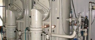
A diagram of an electron beam installation for welding pipes in vacuum is shown in Fig. 6.
In the upper part of the vacuum chamber (1) there is an electron gun (2), powered by a high voltage rectifier (3). An electromagnetic focusing lens and deflection system (4) serve to focus and move the beam. The product movement mechanism (5) is located inside the vacuum chamber. Power is supplied through the electrical vacuum inlet (6). At the bottom of the chamber there is a vacuum system (7). The installation is controlled from the remote control (8).
A preformed tube blank of final length (500–1000 mm) is installed so that the longitudinal edges are adjacent to each other. Then the vacuum chamber is tightly closed and the air is pumped out of it. After reaching the required vacuum, welding begins. During the welding process, the pipe workpiece automatically moves relative to the electron beam.
Rice. 6. Installation diagram for electron beam welding: 1 - vacuum chamber; 2 - electron gun; 3 - high voltage rectifier; 4 — electromagnetic focusing lens with deflection system; 5 — mechanism for moving the product; 6 — electric vacuum input; 7 - vacuum system; 8 — control panel
The disadvantages of the process of welding pipes in a vacuum include the bulkiness and high cost of the equipment, low productivity, and the limited length of the resulting pipes. In order to eliminate these shortcomings, research is being carried out on the creation of chambers with local vacuum and on the use of inert gases as a protective atmosphere.
Laser pipe welding
Laser welding is used for pipes with a wall thickness of 0.25...1.5 mm made of carbon and corrosion-resistant steels.
In the latter case, it has the following advantages compared to welding methods with high frequency currents and non-consumable electrodes:
- less welding power required;
- the weld metal has a finer dendritic structure;
- less intense growth of metal grains occurs in the thermally affected zone (Fig. 7), for example, compared to the pronounced uneven structure of the heat-affected zone during ADS welding (Fig. The concentration of oxides and the formation of “critical” phases, for example titanium carbides, are prevented;
- provides higher strength and ductility of the weld metal;
- increased strength of electric-welded pipes is ensured under conditions of corrosion and alternating stresses.
Rice. 7. Structure of the seam and heat-affected zone during laser welding
Rice. 8. Structure of the weld and heat-affected zone during argon-arc welding
Welding is carried out using a 5 kW CO2 laser. The laser welding diagram is shown in Fig. 9. The weld zone is shown in Fig. 10.
Rice. 9. Scheme of laser pipe welding
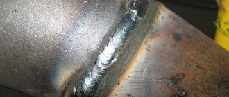
Rice. 10. Weld zone for laser pipe welding
The workpiece is a cold-rolled annealed pickled strip. TESA equipment ensures high-quality preparation of strip edges, precise positioning of the formed pipe relative to the laser beam using an automated seam guide system, protection of the welding zone with inert gas, stable position of the laser beam at the welding point, and constant welding speed. As a result of these measures, a homogeneous seam of minimal width and a smooth transition region of the seam are formed without local thinning.
In the future, it is considered advisable to replace submerged arc welding with laser welding. This will reduce the width of the weld seam and increase the strength of welded pipes with a wall thickness of up to 20 mm.
The technology for laser welding of corrosion-resistant pipes with an outer diameter of 38...55 mm and a wall thickness of 1.5...2.5 mm was developed by Hoesch (Germany).
Oppermann (Germany) uses a pipe welding unit with a 20 kW laser system.
Submerged arc welding
The submerged arc welding diagram is shown in Fig. eleven.
An electric arc burns under a layer of flux between the edges of the workpiece being welded and the metal electrode. Due to the high temperature of the arc (more than 3500 °C), the edges melt and the groove is filled with the metal of the electrode and the base metal. A layer of molten flux protects the liquid metal bath from oxidation. The flux (slag) then hardens, forming a slag crust on the weld surface, which separates from the weld surface. The welding wire, and with it the arc, moves in the direction of welding using a special mechanism. Flux is poured onto the edges of the joint from the hopper in front of the arc.
Automatic submerged arc welding produces large-diameter pipes intended for main pipelines of gas, oil and petroleum products, as well as for the construction of water pipelines, low-pressure steam pipelines, etc.
Rice. 11. Scheme of submerged arc welding: 1 - current conductor; 2 - wire moving mechanism; 3 - wire; 4 - liquid slag; 5 - flux; 6 - slag crust; 7 - weld; 8 — base metal of the workpiece; 9 - liquid metal in the weld pool; 10 - electric arc