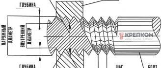
General information and classification of calibers
It should be said right away that gauges do not allow one to completely accurately determine the geometric size of a product; the tool is intended to establish compliance of the part parameters with the dimensions indicated in the drawing. In other words, gauges are used to determine tolerances when manufacturing a part.
Many automakers and builders use this tool to sort parts. Despite the simplicity of the caliber design, it can be used to quickly and easily control a product of even the most complex configuration. True, the tool also has some disadvantages - insufficient versatility and the inability to detect significant deviations in size.
Depending on the type and purpose, calibers are divided into:
- plug gauge;
- ring gauge;
- clamp gauge.
Also, the instrument is usually divided into extreme and normal. Limit gauges have two main parameters, one of which corresponds to the maximum (pass) size of the part, the second – to the minimum (no pass). Normal gauges include the size required for a particular part.
Limit type tools are used more often; normal gauges are usually used as control gauges. In addition, extreme calibers are easy to use without special skills, and the operation of a normal tool requires a high level of professionalism.
The gauges used to carry out control measurements and determine the shape of the part at the initial stage are called working gauges, and those used to control threads are called counter-gauge gauges. There are also receiving gauges used to determine the quality of manufactured products.
Depending on the purpose, there are also several options for the tool. For external threads, threaded ring gauges are used, counter-plug gauges are used for conical rings, for smooth rings, smooth conical plug gauges or conical counter-plug gauges are suitable. Internal threads are measured using smooth or threaded cone plug gauges.
Technological process for manufacturing screw plugs
Depending on the size of the plug thread pitch, there are three main schemes for the technological process of plug thread formation:
- for a step from 0.2 to 0.4 mm - cutting and finishing (polishing);
- for pitches from 0.45 to 1.75 mm - grinding and finishing (polishing);
- for pitches from 2.00 to 6.00 mm - cutting, grinding and finishing.
In the first case, the formation of a caliber thread is carried out by cutting on a precision screw-cutting lathe, and after heat treatment only the thread is fine-tuned.
In the second case, after turning, it is necessary to grind the thread, and it is more cost-effective to grind the entire workpiece without first cutting the thread with a metal-cutting tool. The amount of metal that is removed is relatively small and can be removed immediately using a thread grinder. The final finishing of the thread is done by finishing.
In the third case, a full range of basic technological operations for thread formation is required, i.e. cutting, grinding and finishing. Instead of pre-cutting on a lathe, thread milling can be used in mass production.
At a number of enterprises, threads on gauges with pitch sizes in the range of 0.4-6 mm are not finished after grinding, but are only polished. In addition, the interval of pitches of threads ground on a whole caliber blank is expanded to the limits of 0.35-3 mm. The wear resistance of threaded plugs obtained by such methods has not yet been studied in detail.
The technological process for manufacturing thread plug gauges for medium-sized metric threads (d0 = 14÷33 mm and pitch S = 2.0÷3.5 mm) is the most typical and consists of the following main operations:
- preliminary grinding;
- cutting the second end;
- centering;
- final turning;
- cutting with a cutter or thread milling;
- cutting grooves at the cavities (along the internal diameter of the thread);
- heat treatment - hardening and tempering;
- grinding center holes;
- grinding the tail part of the caliber;
- grinding the working part;
- end polishing;
- engraving markings;
- chamfering by grinding;
- thread grinding;
- removing incomplete turns;
- aging;
- blunting of incomplete turns;
- caliber thread finishing;
- grinding along the outer diameter;
- caliber polishing.
Preliminary operations and thread cutting
Preliminary turning and cutting of blanks for threaded plug gauges is in many ways similar to the preprocessing of smooth plug gauges.
The final grinding of plug gauges usually begins from the tail section, forming a cone and chamfering the end. Then the gauge is turned, moving the clamp to the tail part, and the working part is turned with chamfering at the end. In the case of turning a non-passing plug, the cylindrical flange (trunnion) is also finally ground and the annular groove is machined (Fig. 1). Non-through threaded inserts and nozzles can be manufactured with cylindrical flanges on both sides of the thread. This makes it possible for a significant part of the threaded plugs to take the total length of the blanks the same for both straight-through and non-go-through plugs.
Figure 1. Final grinding of the working part of a no-go threaded plug
Precision threads are cut on special machines that differ from conventional screw-cutting lathes in that they are equipped with a correction ruler. With the help of a correction ruler, the influence of errors in the lead screw and feed mechanism is eliminated; As a result, the cut product receives a more accurate thread pitch.
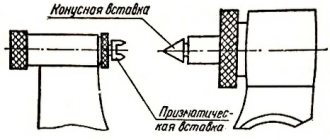
Thread cutting is performed using a prismatic or disk cutter. To obtain the correct thread profile, accurate sharpening and installation of the threading tool is very important. When cutting a thread with a comb, two cases can occur: a) the comb has a pitch equal to the thread pitch of the gauge, or b) the comb has a pitch that is a multiple of the thread pitch of the gauge being cut.
The latter case has a greater advantage when machining gauges with fine threads, since coarse pitch combs can be more accurately manufactured and inspected.
Thread cutting is sometimes divided into preliminary and final (small threads). Due to the widespread use of precision thread grinding machines nowadays, in most cases, threads are cut in one operation.
In mass production, a more productive method is also used - thread milling with a pitch of S = 2.0 mm and higher (Fig. 2). This operation is used as a preliminary operation, since the accuracy of the thread profile is low.
Figure 2. Milling the thread of a plug gauge
Cutting a groove at the cavities - along the internal diameter of the thread ("thread failure") is performed on a lathe using a prismatic or disk cutter. It is necessary that during subsequent machining (grinding, finishing), the cutting tool processes the sides of the thread profile, since under these conditions the shape of the processing tool is retained for a longer time.
To improve machinability when cutting threads, special heat treatment is used. For workpieces made of chromium steel (grades X and XG): a) heating to 820-850°; b) hardening in oil; c) tempering at 700-720° followed by holding for 3-4 hours at a temperature of 680°.
After preliminary mechanical processing, the calibers are hardened and tempered.
Calibers made of chromium steel (grades X and XG) are heated for hardening to a temperature of 820-850°. The heating time for small calibers with a diameter of up to 7 mm is 15-25 minutes, for medium sizes with a diameter of 8-30 mm - 25-40 minutes. And with a diameter of up to 100 mm - up to 80 minutes. Hardening is carried out by cooling the calibers in oil at a temperature of 25-40°. Hardness should be within Rc = 58÷64. Tempering is carried out in an oil bath at a temperature of 150° for 1.5-3 hours.
Final operations, grinding and finishing of threads
The first operation after heat treatment is grinding the center holes (sockets) on the ends of the caliber.
The next operations are grinding the conical tail (Fig. 3), and then grinding the working cylindrical part of the caliber. These operations are performed on a cylindrical grinding machine using (for medium conditions) a grinding wheel made of electrocorundum with a grain size of 46-60 and a hardness of CM1-CM2 with a ceramic binder.
Figure 3. Grinding the tail of a thread gauge
Polishing of the front end (at the working part) is carried out on a copper circle of the plug. polishing head using abrasive micropowder M7-M10.
The operation of engraving markings is performed on an engraving machine using a special needle on the varnish layer (followed by etching). For calibers with a diameter d0 = 1÷14 mm, a headstock with inclined centers is used as a device (Fig. 4), and for calibers with a diameter d0 = 16÷100 mm, a special conical stand is used (Fig. 5).
Figure 4. Engraving of screw plugs up to 14 mm in diameter
Figure 5. Engraving of screw plugs with a diameter of 16 to 100 mm
In the first case, the markings are applied on the conical part of the caliber. Due to the requirements for the location of the markings, installing the caliber in inclined centers makes it possible to position the upper generatrix of the cone parallel to the base plane. In the second case, the marks are applied to the end of the caliber.
After applying the marks, an etching composition is applied to the varnished surface and, thus, etching is carried out, followed by neutralization, varnish removal and final anti-corrosion washing of the caliber.
Marking marks can also be applied using an electrograph, which is often used in the individual production of calibers.
Chamfering the ends of the plug is usually done on a thread grinding machine with a wheel set at an angle.
The next operation is to grind the thread of the gauge. The gauge is installed in the centers (Fig. 6), and the grinding wheel is installed according to the angle of the thread. A special device is used to dress the grinding wheel according to a given profile.
Figure 6. Scheme for grinding threads of plug gauges
Thread grinding is usually carried out in two stages - preliminary and final (this does not apply to gauges with a small thread pitch). Removal of incomplete turns at the ends is carried out by grinding them off. Incomplete thread turns of calibers with a pitch of less than 1.5 mm are dulled manually using an abrasive whetstone.
The aging process of calibers is usually carried out in an oil bath at a temperature of 150-170° for 2-10 hours. The duration of aging depends on the accuracy of the caliber and its size. The larger the diameter and the higher the accuracy, the longer the exposure time, and vice versa. The operation of finishing the thread is carried out on the finishing head (headstock) using an adjustable cast-iron lapping ring (Fig. 7) placed in the holder. The head spindle, together with the fixed gauge, rotates alternately in two directions and, thus, the finishing ring, alternately moving in the axial direction, finishes the thread.
Figure 7. Scheme for finishing the threaded plug gauge
As wear occurs, the adjustable finishing ring is tightened. M28-M14 micropowders and GOI paste (for final finishing) are used as finishing abrasives.
To grind the working part of the caliber along the outer diameter, a grinding wheel made of electrocorundum with a grain size of 60, hardness CM2, and a ceramic binder is used (for average conditions). This operation aims to eliminate blockages and sagging at the tops of the thread profile. The final technological operation is polishing the chamfers, cylindrical pin, end and thread of the caliber. The operation is performed on a finishing head using chromium oxide and aluminum oxide.
Operational allowances, tolerances and dimensions
Operational allowances and tolerances were developed by NIBV MSS for the outer and middle diameters of threaded plug gauges. The layout of allowances and tolerances is shown in Fig. 8 and 9.
Figure 8. Layout of allowances and tolerances on the outer diameter of threaded plug gauges
Figure 9. Layout of allowances and tolerances for the average diameter of threaded plug gauges
Detailed tables of allowance and tolerance values are contained in the work of NIBV MSS “Interoperational allowances and tolerances for thread gauges”. For general characteristics, below are summary tables of the intervals of minimum allowances and tolerances for operational dimensions for the outer (Table 1) and average (Table 2) diameters of threaded plug gauges.
Minimum allowances are based on nominal dimensions.
Data on the limits of the minimum allowances and the tolerance values for the outer diameter of threaded plug gauges (Fig.
| No. | the name of the operation | Range of nominal thread diameters in mm | Minimum allowances | Operating tolerances | ||
| Symbol | Interval of numerical values in mm | Symbol | Tolerance value | |||
| 1 | Rough turning | 6-30 | Ztot. min | 2,0-4,0 | δ1 | A4 |
| 30-100 | 5,0-8,0 | |||||
| 2 | Finish turning | 6-30 | Z1 min | 0,75-1,15 | δ2 | A3a |
| 30-100 | 1,25-1,60 | |||||
| 3 | Pre-grinding | 6-30 | Z2 min | 0,20-0,39 | δ3 | A2-2a |
| 30-100 | 0,30-0,46 | |||||
| 4 | Final sanding | 6-30 | Z3 min | 0,04-0,055 | δ4 | 0,016 |
| 30-100 | 0,055-0,065 | 0,020 | ||||
Data on the limits of minimum allowances and tolerance values for the average diameter of threaded plug gauges (Fig. 9)
Metric thread: M, 1M, 2M, ZM
| No. | the name of the operation | Range of nominal thread diameters in mm | Minimum allowances after surgery | Operating tolerances | ||
| Symbol | Interval of numerical values in mm | Symbol | Interval of numerical values in mm | |||
| 1 | Threading | 6-30 | Z1 min | 0,27-0,45 | δ1 | 0,09-0,15 |
| 30-100 | 0,50-0,75 | 0,16-0,22 | ||||
| 2 | Pre-grinding | 6-30 | Z2 min | 0,10-0,12 | δ2 | 0,017-0,030 |
| 30-100 | 0,12-0,15 | 0,04-0,05 | ||||
| 3 | Final sanding | 6-30 | Z3 min | 0,008-0,010 | δ3 | 0,010 |
| 30-100 | 0,010-0,012 | 0,012-0,016 | ||||
| 4 | Finishing the thread | 6-30 | — | — | δ4 | 0,010 |
| 30-100 | 0,012-0,016 | |||||
Tolerances for grinding and finishing on the average diameter of the thread are assigned according to the manufacturing tolerances in accordance with GOST 1623-89 and GOST 24997-2004 (instead of GOST 1623-46), which also regulate the permissible deviations of the pitch and half the angle of the thread profile.
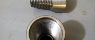
Ring gauges, plug gauges and clamp gauges - their features and purpose
Threaded plug gauges have a one-piece design, complemented by inserts on a conical shank. The tool consists of a threaded part, which is long, and a non-threaded part, which is short. The pass gauge has a full profile, the no pass gauge has from 3 to 5.5 turns in length. In addition, at the end of the non-pass part there is a cylindrical guide. The main task of these instruments is to measure the dimensions of products with the smallest average diameter.
During operation, the plug gauge must be screwed into controlled rings. If the process occurs easily and freely, then the average diameter being checked is not less than the established specific size.
Ring gauges come in two types: they are rigid (non-adjustable) and adjustable. Non-adjustable gauges feature full-width threads, while adjustable gauges have a limited thread profile. In addition, the adjustable rings are equipped with rollers that allow you to adjust the degree of wear. One of the advantages of adjustable gauges is that they can be adjusted repeatedly, thereby increasing the wear resistance and longevity of the tool.
Non-adjustable ring gauges are used to control large product diameters and internal diameters of external threads. The outer diameter cannot be measured this way. Plug gauges can be used to check the degree of ring wear.
The most productive types of gauges are considered to be staples, which are most often used for measuring external threads. Such gauges are easily fixed directly to the product being measured and are quite easy to control and adjust when worn. Unfortunately, such instruments also have their drawbacks: they are easily deformed, leading to significant measurement errors.
TOLERANCES FOR SMOOTH CALIBERS
5.1. The location of the tolerance fields of smooth gauges, as well as the tolerances and values that determine the position of the tolerance fields and the wear limit of the gauges for monitoring the outer diameter of the external thread must correspond to those indicated in Fig. 10 and in Table 7, for monitoring the internal diameter of the internal thread - indicated in Fig. 11 and in table 8.
Damn.10
Table 7
µm
| Td according to GOST 6357 | H2 | HP | Z2 |
| St. 140 to 335 | 16 | 4 | 38 |
| 335 » 850 | 30 | 6 | 54 |
Damn.11
Table 8
µm
| TD1 according to GOST 6357 | H1 | Z1 |
| St. 180 to 375 | 16 | 38 |
| 375 «710 | 26 | 52 |
Features of calculating thread gauges
When designing thread gauges, the following indicators are taken into account:
- step;
- controlled thread tolerance fields;
- make-up length;
- external nominal cross-section.
To calculate metric threads, the nominal internal and average cross-section of the connection is taken into account. For trapezoidal threads, the diameters of the nut (internal and external) and screw (internal) are also taken into account.
The specific shape of the gauge is selected depending on the type of tool.
In modern production, caliber calculations are carried out using special programs.
Basic requirements for calibers
Regardless of the type and purpose, any caliber must meet certain requirements:
- Manufacturing accuracy - the working dimensions of the tool must correspond to the manufacturing tolerances established.
- High rigidity with low weight is necessary to reduce errors in the deformation of gauges (especially large staples) during measurement. Light weight makes it possible to increase the sensitivity of control of medium and large sizes.
- Wear resistance - this indicator is necessary to ensure minimal costs for the manufacture and periodic checking of calibers. For this purpose, the working surface of the tool is made of alloy steel, which is subsequently hardened to increased hardness and chrome-plated.
- The optimal design of the gauges ensures high performance when performing measurements.
- Incorporating heat treatment into the production stage allows for stable tool dimensions to be achieved.
- Anti-corrosion properties are extremely important for the safety of calibers.