Argon welding is an indispensable method with which you can create permanent joints of products made of non-ferrous metals, titanium, stainless steel and other alloys. In addition, this type of welding is characterized by good seam quality and high productivity. The universal capabilities of argon welding also attract home craftsmen. But this equipment is expensive and is practically not purchased for home use. Therefore, more and more craftsmen are starting to think about making an argon welding unit with their own hands.
Technology and application of argon welding
Argon welding is a bit like ordinary arc welding, but it uses a shielding gas, argon, to protect the weld pool. This inert gas has a number of properties unique to it.
- Since argon is 38% heavier than air, it penetrates well into the weld pool and protects it from gases in the atmosphere. Thanks to this, the welding seam is obtained without the formation of an oxide film, which improves the quality of the connection.
- Argon is present in the air, so it is a byproduct of oxygen and nitrogen produced from the atmosphere, and is the least expensive of the shielding gases for welding.
The welding process in argon occurs according to the following principle. Literally 1 second before the arc ignites, argon is supplied to the burner. The welder brings the electrode to the part prepared for connection and presses the power button. But since high ionization is required to ignite an arc in a protective gas environment, an oscillator comes into play.
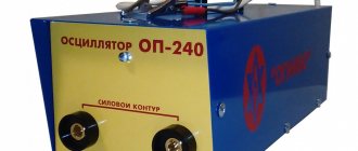
An oscillator is a device that produces high-frequency and high-voltage pulses that can ionize a gas and ignite an arc between the electrode and the workpiece.
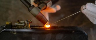
After ignition of the arc, filler wire is supplied to the joint of the parts manually or automatically. Parts are welded by melting the additive, the metal of which falls on the molten edges of the workpieces being joined.
Traditionally, argon welding refers to the joining of metals using a non-consumable tungsten electrode that creates an arc and an additive in the form of a metal rod or wire. This type of welding has the international designation “TIG”.
Argon welding is used in the following areas.
- Frame construction. Welded seams can withstand constant loads.
- Joining of pipes of both steel and non-ferrous metals, including pipes of various alloys.
- Connection of dissimilar metals.
- Splicing of almost any metals together: titanium, copper, aluminum, stainless steel, bronze, brass, cast iron, etc. This is especially important for the automotive industry.
- Manufacturing of decorative and jewelry items.
general information
Argon arc welding is in many ways very similar to manual arc welding, only argon shielding gas and filler wire are additionally used. At the same time, a non-consumable tungsten electrode is used. The electrode helps ignite the arc and the wire forms the seam. In the world this welding technology is called TIG.
The essence of argon arc welding is simple. First, the torch supplies argon to the welding zone. A second after the gas is supplied, the welding arc is ignited. To ignite an arc, you need to bring a torch with an electrode inside to the metal and press the switch. But why is the arc ignited? After all, there is no reason for this.
An oscillator solves this problem. It ionizes the gas and thereby allows the arc to ignite in argon vapor.
After the arc has stabilized, filler material can be fed into the weld pool. This can be done manually or using a feeding mechanism. The arc melts the metal, but the filler wire allows you to form a weld bead. The wire melts with the metal and mixes with it.
Next, we will tell you what you will need to assemble your own argon welding machine.
Elements for assembling a homemade apparatus
To assemble equipment for argon welding, you will need the following items:
- DC or inverter type welding machine;
- oscillator;
- inverter protection unit;
- burner;
- argon cylinder;
- gas reducer;
- gas hose;
- welding cables.
Current source
As a current source for TIG welding, you can take a regular welding transformer and adapt a diode bridge at its output to rectify the current. You can also use a welding straightener. But for both types of devices, you will also need to add an oscillator, which will facilitate contactless ignition of the arc.
On the Internet you can read that the easiest way to do argon welding is from an inverter. But there are several nuances here. There are inverters that already have built-in TIG welding capabilities. In this case, it is enough to connect a hose with a torch for argon welding to the device, connect the hose to an argon cylinder, and the unit is ready for work. But first you need to switch it to TIG mode and set the required current.
It should be noted that such inverters already have a built-in oscillator and the necessary protection.
Inverters without a built-in TIG welding function cannot be used for this purpose. Even if you connect an external oscillator to it, the inverter will simply burn out. To prevent this from happening, you will need a small modification of the inverter, which consists of adding a protection unit to its circuit. This block can be assembled together with the oscillator on one board and placed in a separate case. You will get a small attachment for the inverter.
Oscillator and protection unit
As mentioned above, a welding inverter will require a special attachment for TIG welding. You can assemble it with your own hands according to the diagram provided below.
This circuit includes a protection block (located on the left) and an oscillator. The latter can be purchased in China or assembled yourself. You can find out how the above circuit is assembled by watching this video.
Burner
For argon welding, a special torch is used, consisting of a ceramic nozzle and a tungsten electrode holder.
Also on the burner there is a start button and a gas supply valve. The burner can be assembled from components, which are sufficient on Chinese websites, or you can buy a ready-made (assembled) one there.
Argon cylinder
For safety reasons, it is customary to paint all gas cylinders in different colors and put inscriptions on them in different colors. Below is a picture that shows all types of gas cylinders with markings and colors corresponding to their contents.
As can be seen from the figure, black (with a white stripe) or gray (with a green stripe and inscription) cylinders are used for argon. For TIG welding, purified argon is used. Therefore, you will need to purchase a gray cylinder with a green inscription “Pure Argon”.
Advice! For professional use, cylinders with a capacity of about 50 liters and a large weight are used. But for domestic use, a 10-liter cylinder will be sufficient, which can be moved independently.
Gearbox
Since the gas in the cylinder is under high pressure, a reducer is required to supply it to the burner. This device shows the pressure in the cylinder and allows you to adjust the gas flow rate through the hose leading to the burner.
The reducer must be selected strictly for a specific gas, that is, in this case, for argon. Usually the device has the same color as the gas cylinder.
Hose and welding cables
If you assemble a hose for argon welding yourself, it will turn out to be thick and difficult to bend, since you need to place an electric cable and a gas hose in it. In addition, you will need to separately purchase connectors for connecting to the torch and to the inverter (if you use an inverter with TIG welding capabilities). A ready-made sleeve for argon welding can be purchased in the same place as the torch.
Welding AC-DC-TIG/MIG-MAG in shielding gases.
The design of the welding machine we bring to your attention was developed by a participant in specialized forums under the nickname sam_soft .
Introduction:
A huge number of homemade inverter welders for manual welding with coated electrodes (MMA or SMAW) have been made by radio amateurs in recent years.
However, other types of electric welding have been left aside, namely, electric welding in a shielding gas environment. This development is an attempt to fill this gap and create a simple and affordable welder for self-production for manual welding in an argon environment (TIG or GTAW) with direct or alternating current, as well as for semi-automatic welding in mixtures of carbon dioxide and argon or in carbon dioxide (MIG/MAG or GMAW). I believe that the manufacture of this design is quite accessible to a “radio destroyer” who has previously dealt with ordinary “barmaleiniks”, and the presence of a microprocessor does not require any special knowledge in this area.
Device characteristics:
1. min-max welding current in AC-DC TIG mode: 10 - 210 amperes. Step adjustment in 5 amp increments. 2. min-max output voltage in MIG mode: 14 - 26 volts. Step adjustment in 1 volt increments. 3. adjustment of the rate of rise and fall of current in AC-DC TIG mode: 1 -10 sec. Independent in steps of 1 sec. 4. gas/post gas start time for AC-DC TIG mode: manual control from the torch button, unlimited time. 5. crater filling time and crater filling current for AC-DC TIG mode: fixed 1 sec, 10 amperes 6. additionally for AC TIG mode: a). AC frequency adjustment: 20 - 200 Hz. Adjustment in steps of 10 Hertz b). cleaning time adjustment (balance): 25 - 75% of the period. Adjustment in 5% increments c). cleaning current adjustment (ICC): 10 - 100% of the reference current. Adjustment in 5% increments
7. TIG control mode: 4T 8. MIG control mode: 2T 9. Ignition in TIG mode: lift 10. Remote control of current for TIG and voltage for MIG with the appropriate step. 11. Welding wire feed mechanism: external.
The device also consists of six functional units: a DC-DC converter, a DC-AC converter, a control circuit, a remote control decoupling circuit and an auxiliary power source.
1. The DC-DC converter is made according to the well-known skew bridge topology, which has been disassembled down to the last screw on radio-destroying forums. A description of his work is not provided. It is possible to use other single-cycles - fixed and possibly superfixer with appropriate output power. However, to ensure maximum output power during a network sag, for stable ignition operation and a stable welding arc in the AC DC TIG mode, it is highly desirable to maintain the transformation coefficient of the power transformer. In addition, it is recommended to make the output choke as it is designated in the original. Everything else is up to the taste and color of the sculptor, naturally without nonsense and fanaticism. The following are connected to the output of the DC-DC converter: a torch for DC TIG in the appropriate polarity, an input of the DC-AC converter, a welding wire feeder for MIG MAG.
2. The DC-AC converter is made using a bridge circuit using GA200HS60S1 IGBT power modules. Safe switching of modules in AC mode is ensured by the DR-C snubber and control circuit. It is not recommended to connect AC TIG welding leads with a total length of more than 8 meters. This increases the parasitic inductance of the welding circuit, reduces the rate of rise of the current when passing through zero, degrades the stability of the AC arc, and can also lead to overvoltages on the power modules. The GA200HS60S1 power modules can be easily replaced with “bayans” of field-effect transistors, which is often done by the Chinese. However, taking into account their required number, the complexity of management and installation, this option can only be considered as a hopeless option or when there is the required number of “free” field workers. Because the total cost of their purchase will not be much less than IGBT modules.
3. The control circuit primarily ensures synchronization of the operation of both power converters in AC TIG mode, current protection of the DC-DC converter and stabilization of the output voltage in MIG-MAG mode. Other monitoring and control functions: - charging relay control - temperature control - fan control - switching welding modes - input and display of welding parameters. - remote control.
4. The decoupling circuit provides 100% galvanic isolation of the control circuit from remote control elements - burner buttons, remote control buttons. A miniature stabilized transformer power source from a burnt-out antenna amplifier with a stabilized output voltage of 12 volts, slightly larger than a matchbox, is used as a power source for the decoupling relays. When selecting a suitable source, pay attention to the output voltage of the rectifier. In the original it is 22-23 volts, which will provide a reserve in the event of a network failure at maximum current.
5. The auxiliary power supply is based on the famous TOP250. This is a classic circuit from a datasheet for a microcircuit, calculated from “Sanyok”. The power supply provides stabilized +14.5 volt power with a current of 2-3 amperes, as well as three additional low-power galvanically isolated +17 volt power supplies for powering optodrivers
The processor board diagram from the author sam_soft in DipTrace format is here.
The same diagram from the site editor: (click on the image to enlarge)
DC-DC board diagram from the author sam_soft in DipTrace format here.
DC-DC diagram from the editor:
The DC-AC converter circuit from the author sam_soft in DipTrace format is here.
DC-AC diagram from the editor:
6. PCB layout from SANEK here. Updated November 24, 2009.
Here is a working layout of the proposed device:
And here are pictures of the control board from SANEK
7. Software from sam_soft.
HEX file here.
All versions, starting from this one, will be numbered and described. The version number will be displayed on the display when the device is turned on, while the containers are charging, that is, 2-3 seconds, for example, u102 . I don’t rule out that there are some minor bugs and problems somewhere, it’s not so easy to check everything, it takes a lot of time and argon. Therefore, if any problems are found, then you need to know exactly what the problem is and in which version. Everything that is found from fleas will be fixed as time permits. The government scheme will no longer be redone. I checked the current and voltage calibration quite accurately. Cooked with TIG on DC and AC and calibrated using the shunt. This is the most reliable method, since everything jumps on the MMA, and on the ballast you can accurately set the voltage and current. It's not so easy in an arc. The PA was calibrated on the ballast at 15 -18 - 20 - 22 - 25 - 27 volts, with a load from 40 to 160 amperes. Fractions of a volt change in voltage. So everything should be OK for MIG.
Briefly about management.
Everything that I wrote earlier about DC AC modes and distances remains the same. For the PA, the afterburner voltage, afterburner time and cut-off current are additionally made. Voltage adjustment is the same as before. Afterburner voltage - displayed in volts, which will be added to the base one. This setting is activated by pressing the lower left button with the letter u displayed on the left. Well, then +/-. The value of max + depends on the base voltage but not more than 30 volts in total with the base voltage. Min - zero. When you press the bottom right, you set the time in seconds (there will be a letter d on the left on the display) during which the force is active, the range is from 0 to 5 seconds. When you press both, the cutoff current is set (symbol c on the right) in 20 ampere increments. Max value 200, min 60. Default 200 amperes. These settings are not saved in the iprom, until, if they are useful, we will save them. Maybe someone can check it out in their spare time, write to the forum. If this doesn’t make any sense, we’ll do something else, pulse for example. All others, according to TIG AC, DC, current frequency, balance, cleaning current, slopes are automatically saved at the start of welding, if they have changed since the last save. Well, then they naturally load when the device is turned on.
Channel ADC1 is set to 95 degrees. This channel is intended for measuring the temperature of modules, for which 100-110 degrees are acceptable. But LM sensors are designed to measure up to 100 degrees, so I settled on 95 degrees. ADC0 - I have diodes. It's 80 degrees.
Assembly and configuration.
A correctly assembled brewer with the specified parts requires almost no adjustment, just like any barmaley. Setting up usually comes down to sequential checking of nodes and identifying the jambs that are sure to exist. So I. MMA. The MMA regime is the guarantee of the life and health of everyone else. Therefore, we approach work in this mode especially carefully. We consistently check everything related to DC-DC. For those who have soldered barmaleys, much will seem unnecessary, but this opus is also intended for novice welding nuts. In addition, there are some control features. That’s why I’m writing in more detail. To avoid holes in your budget, under no circumstances proceed to the next item if you have doubts or questions about the previous one. It’s better to think about it or ask on the forum if that’s not the case. I don’t rule out that I made a mistake somewhere in the scheme or even in this opus.
1. We solder the power supply and start it according to the method described more than once, including on this site, using LATR and an isolating transformer. The supply voltage of the optodrivers should be within 17-18 volts. We load the feeder at +15 at 1-1.5 amperes, mats and control the heating of the output diode, trans and TOP, suppressor, leave it under load for a couple of hours. If you don't freak out, let's move on.
2. Solder the control board without a 20 ohm resistor, the one from the UC output (pin 6). If the microcircuits are on sockets, then we check the voltage on the power pins without them. If not on sockets, then we solder them after checking the power supply. We plug in the microcircuits, without an optocoupler. We throw +5 volts onto the optocoupler emitter through a 300 - 500 ohm resistor. This simulates the output voltage XX, otherwise the “short” protection will work and the control will turn off after making three attempts to turn on. It will be possible to revive everything only by turning off the power. Set the switch to the MMA position. Be sure to connect temperature sensors, otherwise there will be uncertainty at the ADC inputs and the control will turn off PWM.
3. Calibrate temperature sensors. Temperature protection of any cooker is the key to the life of the cooker. I’ve heard tales more than once about how I’ve been cooking all day and nothing gets hot, but I’ve also driven my crafts on ballast more than once, and I’ve seen something completely different. Therefore, this nonsense about frozen transistors or diodes is not discussed. Version 103 adds the ability to independently calibrate temperature sensors via IPROM, since sensors 335 have an initial error of up to 6 degrees, and 335A up to 3 degrees, which I have noticed more than once. Therefore, instead of selecting sensors, programming or attaching potentiometers, it is easier to calibrate the zero shift programmatically. It is advisable to do this at a temperature of 25 degrees. The first four bytes in the IPROM are the zero shift of both sensors, two bytes for each channel. In version 103, in MMA mode, when two control buttons are pressed simultaneously, the varica displays the temperature of both channels, like a thermometer.
We will use this. If the readings of the environmental thermometer differ greatly from what the display shows, then it is necessary to change the shift values in IPROM. Values in IPRM are stored in the following order - first the low byte, then the high byte. If you open IPROM 103 with the programmer, you can see that the first 4 bytes are 20 02 20 02, which is decimal 544 544. If the display meter shows more than the actual temperature, then the shift needs to be increased. And vice versa. A change in calibrator offset of 2 is a change of one degree.
4. Immediately after turning on the power, while charging the electrolytes, the display should show the version number of the cupcake - u102. Then the device switches to the current setting display mode. At pin PB01 of the processor, we observe short UC clock pulses with a frequency of approximately 75 kHz. If they are not there, then look for a jamb. Press the + buttons and see what happens. The indication changes, which means the buttons are alive. The current setting values for MMA vary from 10 to 160 amperes. In this case, the reference voltage should change synchronously on the first UC pin. At the UC output, we use an oscilloscope to observe pulses with a frequency of 37.5 kHz and a duration of approximately 11.5 microseconds. 5. Solder a 20 ohm resistor (to the UC output), solder and collect DC-DC power, without a choke and output diodes. WITHOUT SUPPLYING 300 volts, turn it on and see what’s happening on the IGBT DC-DC gates. The pulses should be 13 volts, with steep fronts and cuts, lasting 3-4 hundred nanoseconds, and of course there will be Miller shelves. We pull out one of the sensors - the fan relay should operate and the PWM should be cut off. We do the same with the second sensor. We screw one sensor at a time to an aluminum plate along with a thermocouple and heat it with a soldering iron. Let's see at what temperature the fan starts and the PWM switches off. One sensor is set to approximately 80 degrees (these are DC-DC diodes for the output) The second is set to 95 degrees - this is for modules. Don't confuse the sensors. The fan turns on at approximately 400 degrees, hysteresis is approximately 50 degrees.
6. We carefully check the DC-DC power installation and the phasing of the power transformer. We drink beer and go to bed.
7. Tomorrow, when we are sober, we will again check the installation of power circuits. We install an optocoupler. We connect the oscilloscope to the load resistor CT (current transformer). In the +300 volt gap - we connect a 200-250 watt lamp and supply power. If the classic BACH did not start playing, then this is encouraging. We look at the Lamp, its thread SHOULD NOT burn. Its burning is a clear sign of a jamb and it may end in classics - the music of Bach. The glow of the thread can only be noticeable in the dark. Let's look at the magnetizing current. There should be no sharp bends at the end of the straight stroke. If the saw still crawls upward parabolically, then it is possible that the ferrite is scorched or something else is wrong. With real Epkos everything should be OK. We cut it down. We drink beer, think and go to bed. If there is an LATR, then it is better to use it and smoothly increase the supply voltage of the power circuit and monitor the magnetizing current on the CT load resistor.
8. Tomorrow we check everything again , then screw on the diodes and inductor. We check the phasing of the CT. To do this you will need a 2-3 ohm resistor, 10-20 watts. We connect the oscilloscope to the secondary of the power transformer. Turn on the cooker and set the current to minimum in MMA mode. We poke a load of 2-3 ohms at the output. terminals. The duration of the pulses on the oscil should collapse. If not, swap the wires of the current transformer.
9. Check the short circuit. To do this, connect the oscilloscope to the reverse diode, connect the welded hoses through the shunt. Set the current setting to minimum. Turn on the cooker and shorten the holder with the mass. The short-circuit current at the minimum setting should be in the region of 30 -40 Amperes. If not, we'll look for a jamb. If everything is so, then we change the current setting from minimum to maximum. In this case, short pulses at the output should not exceed 250-300 Volts.
10. We are looking for a decent ballaster like RB 300 or a decent nichrome coil, 30 squares. If there aren’t enough squares, then we’ll have to come up with something to cool it. We turn up the current ampere 20 -30, throw the holder onto the ballast. It might pass out after a while. It's still the same antistick. Therefore, we quickly increase the current to 60 -80 amperes. We feel and smell what and how it is heated. Turn off and repeat. At first, it is better to play around with ballast without fanaticism. You never know. It would be advisable to conduct a control 10-minute run at 100 amperes 26 volts and in a warm room. If nothing dies, then there is a very high probability that everything will continue to be okay and will never die. During the race, it is advisable to use a thermocouple, or even better, a pyrometer, to monitor the temperature on the control elements - transistor radiator, output diodes, transformer. You never know what's wrong. When approaching the critical temperature of the element, if the protection does not work, it is better to turn it off yourself and try to understand why it did not work. For a transformer, I consider the critical temperature to be 100-105 degrees. For transistors and diodes, the radiator temperature is 80-85 degrees. DC DC is assembled on 4 computer radiators with a copper base. All without Tapmex. Two semiconductors for each radiator. PN of such a design is not bad. At a maximum current of 160 amperes 27 volts, exactly more than 50%.
11. Again we connect the scilloscope to the CT load resistor. We load it onto ballast and slowly increase the current to the maximum value. We look at the trapezoid on the oscilloscope. The tilt (lift) of the trapezoid must be linear. Nonlinearity is bad. A downward bend is most likely a saturation of the CT. This is the most dangerous thing. Bend up - throttle saturation.
12. Take welding electrodes 2-3-4 mm. Let's cook. We are pleased with the completed work on assembling the brewer. This work is not easy, but there is a certain pleasure from it, incomparable. Assembling any inverter cooker requires special care and attention. It's like walking on the edge. That's why it's a thrill
In cupcake number 103, MMA arc rigidity adjustment has been added. It is activated by pressing the left control button in MMA mode and then using the +- buttons we add rigidity to a simple “bayonet” (volt-voltage curve of the arc).
The threshold is set by pressing the right control button and then +-. Therefore, if anyone has an interest and desire for this matter, then he can try to choose the CVC that is necessary and comfortable for himself. There is often a lot of subjectivity here: one person likes it this way and another that way. You can play with this endlessly.
II. MIG-MAG. If MMA works 100% as it should, then there are minus body movements. Set the switch to MIG mode. We cut off the TIG burner and use its button. We cut off the shunt with the head and the pointer voltmeter. We connect the load, set it to 15 volts. We press the button - look at the voltmeter, it should be 15 volts. We change the load there so that the current was up to 150 -160 amperes and look at the voltage. It should always be 15 volts, regardless of the current. Or rather, for current up to 200 amperes. Next, the cutoff begins. We check the same for 18 - 20 - 25 - 27 volts.
If the home network is not important, then it is possible that 160 amperes of current cannot be squeezed out at 26 - 27 volts. My network at home is single-phase 220, but it is strong. We are looking for or making our own wire puller with a gas valve and a speed regulator.
When connecting, please take into account that one wire of the button connector has a low-current potential of +12 volts, isolated from the rest of the control of the device. This can be used and, in addition, a zero potential can be derived from the same source from the burner button relay. To do this, we directly connect the output of the torch button to the torch inputs on the welder, and connect the ground potential of the button relay in the connector with the ground of the feed control circuit. In this case, the torch button directly closes the power supply circuit of the decoupling circuit relay and simultaneously supplies +12 to the relay, transistor, optocoupler, or something else to activate the wire feeding circuit. Perhaps there are other options. You can try to assemble my broach from the previous welder. If anyone needs it, I'll post it. It seems that Sanyok also sculpted the couple. It’s possible that things won’t be any worse for him.
III DC TIG. there shouldn't be any problems here. If the MMA is working correctly, then we turn on the burner, argon and immediately go. We check the ignition and the operation of the slope up and slope down. Mastering the elevator takes 5 minutes. On DC with thorium electrodes everything is very soft and smooth. Poking and sticking are almost imperceptible, as is damage to tungsten. The min electrode I tried was thorium 1.6. I remind you once again. The burner operating mode is 4T. Namely: press the button - start the gas. Let's keep up the pace. I usually hold the gas a little longer during the first start in order to push the air out of the tract, and in subsequent starts I practically don’t hold the gas start. We release the button - voltage is supplied to the output. We light the arc with a short poke. I usually place the torch on the nozzle and then lightly ignite the arc with a short side or straight poke with a lift. Vidiva dropped earlier. Let's see how slope up works. We cook without holding or squeezing anything. Tired of cooking - press the button and hold it. The slope down should work and the arc should go out on its own. Hold the button for the desired post throttle. All. The default values stitched into IPROM for slope up-down are 2 and 3 seconds, respectively. Adjustment - by pressing the left and right control buttons. Yes, with the start of welding, MIG voltage, TIG current, slopes, as well as frequency, balance, cleaning current for the AC, if they have changed since the last save, are automatically saved in the IPROM and then read out the next time the machine is turned on. IV AC TIG. Here, be careful not to turn on the DC AC without its snubber UNDER ANY SAUCE. The snubber will provide protection for modules at currents of up to 50-60 amperes until quarantine shaping begins. Without it, it’s easy to burn the modules. 1. In AC mode, check the operation of the frequency change buttons:
balance,
cleaning current.
It is impossible to control this with an oscillator until we start cooking or loading with ballast. Therefore, we take the word of the display meter. 2. Solder the driver board. We cut off the isolated power supply and the burner (or just some kind of short circuit button). Switch to AC mode. We close the button and watch the oscillations with a two-channel on the drivers. We look carefully and look again at the pinout of the modules. Somehow it was done in a bad way, or maybe not. Is there anything wrong on the board? If not, then we drink beer and go to bed. 3. Look at the datasheet on the GA200HS and check the DC-AC installation again. Drivers - cut them off with power, screw the power buses to DC-AC and plug in the welder. We press the burner button. The DC-DC should start up and supply power to the DC-AC. Check with a voltmeter that it is working. If at the same time nothing grunted or clunked, then there is a possibility that the DC AC is twisted correctly. 4. We cut off the power supply to the optodrivers. We sculpt the oscillation signal to any of the speaker outputs. Ground to minus AC power. We turn on the welder. Press and release the button. As always, the valve relay clicks on the TIG and a constant signal should appear on the output AC in EP polarity. If the polarity is reversed, then we swap the synchronization of the drivers. 5. Take a load of three or four ohms, repeat the start and push the load to the output. About a second after EP a change should appear. It will probably not be possible to synchronize the oscill accurately. But this is not important, it is important to see the very fact of change. We look at the voltage pins on the modules. 5. Change the frequency and balance settings. Let's do it again and see. 6. Increase the load, approximately 1 ohm. We look at the voltage pins at the moment of switching modules. Their value is up to 100 - 150 volts. Depends on current. 7. If there is a finely inductive ballast (4-6 microhenry), then use it and gradually increase the current, watch the pokes. At first I didn’t have such a ballast, so I immediately started cooking, initially setting the minimum current to 10 -15 amperes and a frequency of about a hundred hertz. He cooked, looked through the glass at the arc and out of the corner of his eye at the oscil behind the pokes. You can ask your wife, a child of conscious age, or someone else to take pictures of the oscillations and then look at the pictures yourself and think. That's what I did at first. 8. Raise the current to 30, then to 50 amperes. The pokes should grow. The arc or ballast begins to hum noticeably, this is normal. 9. After 50 - 60 amperes, the growth of pokes should stop. Again . Pay special attention to the pokes. It is not so easy to heat up modules or overload them with current from a household network. They have 250 amps DC at 100 degrees case. It’s hard to try to bring them to this state. But it’s easy to knock them out with a poke of the voltage at the moment of switching. Therefore, if with an increase in current after 60 - 70 amperes the pokes continue to grow, then the thing is wrong. They should not be more than 300-350 volts in any situation. If not, then we are looking for a jamb.
Afterburner duration Afterburner voltage for MIG
MMA mode, current afterburner
Basically everything. If possible, I’ll take photos of the key oscillations, if anyone needs them. If you have questions, ask here, on the forum in the appropriate topic.
To be continued, as well as additions, changes and clarifications follow...
Algorithm for assembling a welding machine
Assembling equipment for argon welding from an inverter is quite simple.
- Connect the protective unit with the oscillator to the inverter according to the diagram above.
- The ground cable must be connected to the oscillator terminal with the “+” sign. The cable that goes to the burner is connected to the terminal with the “-” sign. For aluminum welding, the cables are connected in reverse.
- Connect the burner to the sleeve with the cable and gas hose.
- Screw the reducer to the argon cylinder.
- The gas hose must be connected to a reducer mounted on an argon cylinder.
- Connect the inverter to a 220 V network, and the oscillator to a 6 V power supply.
After this, the DIY TIG welding machine will be ready for use. But first it must be configured correctly.
What should you remember when working with argon?
Chemical properties of aluminum.
Working with argon when welding aluminum requires some precautions:
- Each worker must know perfectly all the operating principles of a welding machine, the rules of its operation, types of welds and connection methods, what properties the types of metals and alloys used have, and how all the structural parts interact with each other.
- It is necessary to have basic skills in providing medical care for all types of electrical injuries, thermal injuries and gas poisoning.
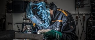
- It is mandatory to use all personal protective equipment during welding. The face, eyes, arms, legs, torso must be dressed in protective clothing, which will help avoid not only electrical injuries, but also save lives.
- Full compliance with all fire safety standards, as work is carried out using flammable and explosive materials. It is necessary to have a working fire extinguisher and be able to use it if necessary.
- It is necessary to ensure constant ventilation of the room in which welding work is carried out using gas to avoid poisoning with this substance.
- All elements of the electrical circuit must be carefully isolated from each other.
- The malfunction of at least one of the mechanisms of the welding machine does not allow its further operation without repairing the breakdown.
Thus, you can be convinced that a welding machine for welding aluminum can be completely made with your own hands, without spending so much time and materials.
Setting up finished equipment
A homemade argon welding installation requires the following settings.
- Sharpen the tungsten electrode on a sharpener until it looks like a needle. This is done so that the arc is concentrated at the end of the needle and does not “walk” in different directions.
- Take a torch and install a tungsten electrode into it. The diameter of the electrode must correspond to the collet in which it is fixed.
- Open the valve on the burner and adjust the required argon flow rate using the reducer (a flow rate of 12-15 l/min will be sufficient), then close the valve on the burner again.
- Turn on the oscillator and bring the torch with the electrode to the metal to which the ground cable is connected.
- When you press the power button, an arc should appear between the metal and the electrode at a distance of about 0.5 mm.
- Turn on the gas supply and press the button again. In this case, the arc should be ignited at a distance of 10 mm or more.
After carrying out the simple settings described above, we can say that the device with the TIG function is completely ready for work.