The linear (specific) (per unit length) active resistance ro at a frequency of 50 Hz and the commonly used sections of aluminum or copper wires and cable cores can be taken equal to the linear ohmic resistance. The phenomenon of the surface effect begins to noticeably affect only with sections of the order of 500 mm2.
Active resistance is the resistance when alternating current flows through a conductor, ohmic is the resistance when direct current flows through the same conductor. For steel-aluminum wires, the phenomenon of surface effect is also insignificant and may not be taken into account.
The temperature of the conductor material, which depends on the ambient temperature and the load current, has a significant influence on the active resistance.
In general, the linear (specific) reactive They are determined by the relative arrangement of phases and geometric parameters. When calculating symmetrical operating modes, average values are used (regardless of the transposition of line phases).
Specific resistance of metals. Table
The resistivity of metals is a measure of their ability to resist the passage of electric current. This value is expressed in Ohm-meter (Ohm⋅m). The symbol for resistivity is the Greek letter ρ (rho). High resistivity means the material is a poor conductor of electrical charge.
Electrical resistivity is defined as the ratio between the electric field strength inside a metal and the current density within it:
where: ρ - metal resistivity (Ohm⋅m), E - electric field strength (V/m),
J is the value of electric current density in the metal (A/m2)
If the electric field strength (E) in a metal is very high and the current density (J) is very small, this means that the metal has high resistivity.
The reciprocal of resistivity is electrical conductivity, which indicates how well a material conducts electric current:
Where:
σ is the conductivity of the material, expressed in siemens per meter (S/m).
Electrical resistance
Electrical resistance, one of the components of Ohm's law, is expressed in ohms (Ohms). It should be noted that electrical resistance and resistivity are not the same thing. Resistivity is a property of a material, while electrical resistance is a property of an object.
The electrical resistance of a resistor is determined by a combination of its shape and the resistivity of the material from which it is made.
For example, a wirewound resistor made from a long, thin wire has a higher resistance than a resistor made from a short, thick wire of the same metal.
At the same time, a wirewound resistor made of a high resistivity material has greater electrical resistance than a resistor made of a low resistivity material. And all this despite the fact that both resistors are made of wire of the same length and diameter.
To illustrate this, we can draw an analogy with a hydraulic system, where water is pumped through pipes.
- The longer and thinner the pipe, the greater the resistance to water.
- A pipe filled with sand will resist water more than a pipe without sand.
Wire resistance
The amount of wire resistance depends on three parameters: the resistivity of the metal, the length and diameter of the wire itself. Formula for calculating wire resistance:
where: R - wire resistance (Ohm)ρ - metal resistivity (Ohm.m)L - wire length (m)
A - cross-sectional area of the wire (m2)
As an example, consider a nichrome wirewound resistor with a resistivity of 1.10×10⁻⁶ Ohm.m. The wire has a length of 1500 mm and a diameter of 0.5 mm. Based on these three parameters, we calculate the resistance of the nichrome wire:
R=1.1*10-6*(1.5/0.000000196) = 8.4 Ohm
Nichrome and constantan are often used as resistance materials. Below in the table you can see the resistivity of some of the most commonly used metals.
Surface resistance
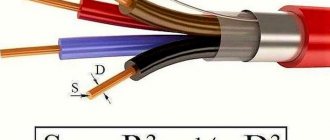
The surface resistance value is calculated in the same way as the wire resistance. In this case, the cross-sectional area can be represented as the product of w and t:
For some materials, such as thin films, the relationship between resistivity and film thickness is called sheet sheet resistance RS: where RS is measured in ohms. For this calculation, the film thickness must be constant.
Often, resistor manufacturers cut tracks into the film to increase resistance to increase the path for electrical current.
Properties of resistive materials
The resistivity of a metal depends on temperature. Their values are usually given for room temperature (20°C). The change in resistivity as a result of a change in temperature is characterized by a temperature coefficient.
For example, thermistors (thermistors) use this property to measure temperature. On the other hand, in precision electronics, this is a rather undesirable effect. Metal film resistors have excellent temperature stability properties. This is achieved not only due to the low resistivity of the material, but also due to the mechanical design of the resistor itself.
Many different materials and alloys are used in the manufacture of resistors. Nichrome (an alloy of nickel and chromium), due to its high resistivity and resistance to oxidation at high temperatures, is often used as a material for making wirewound resistors. Its disadvantage is that it cannot be soldered. Constantan, another popular material, is easy to solder and has a lower temperature coefficient.
Source: https://www.joyta.ru/7968-udelnoe-soprotivlenie-metallov-tablica/
Inductive reactance of wires, cables and lines
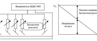
Inductive R for one km with fifty hertz is determined using a special formula:
- x=0.144*lg(2*a(cp))/d+0.016*μ=x0'+x»0,
- a(cf) – cf. length between the axis of several wires, in more detail
- a(cp)=3 root(a1*a2*a3),
- a1, a2 and a3 are the length between the axis in different phases. d is the outer diameter. μ—relative magnetic permeability. x'0 is external outside the line. x»0 - internal inside the line.
Conductivity and resistance of overhead and cable lines
In order to calculate the electrical network for voltage loss, it is necessary to know the parameters of the lines, namely their resistance and conductivity. If calculations are made for DC circuits, then it is quite enough to know only the ohmic resistance of the line. But when calculating an AC line, ohmic resistance alone is not enough, and in addition to active resistances, it is also necessary to know the inductive reactances and capacitive conductivities of wires and cables.
Active resistance of wires and cables
It is known from electrical engineering that the total resistance under equal conditions to alternating and direct current will differ. This also applies to wires and cables. This is due to the fact that the alternating current is distributed unevenly across the cross section (surface effect). However, for wires made of non-ferrous metals and with an alternating voltage frequency of 50 Hz, this effect does not have too much influence and can be neglected. Thus, when calculating conductors made of non-ferrous metals, their resistance to alternating and direct current is assumed to be equal.
In practice, the active resistance of copper and aluminum conductors is calculated using the formula:
Where: l is the length in km, γ is the specific conductivity of the wire material m/ohm∙mm2, r0 is the active resistance of 1 km of wire per phase Ohm/km, s is the cross-sectional area, mm2.
The value of r0 is usually taken from reference tables.
The active resistance of the wire is also affected by the ambient temperature. The value of r0 at temperature Θ can be determined by the formula:
Where: α – temperature coefficient of resistance; r20 – active resistance at a temperature of 20 0С, γ20 – specific conductivity at a temperature of 20 0С.
Steel wires have significantly higher active resistance than similar wires made of non-ferrous metals. Its increase is due to a significantly lower specific conductivity and the surface effect, which is much more pronounced in steel wires than in aluminum or copper. Moreover, in steel wires there are losses of active energy due to eddy currents and magnetization reversal, which is taken into account in equivalent circuits of lines as an additional component of active resistance.
What is resistance, its nature
Resistance (denoted by the Latin letter R) is one of the main characteristics of conductors. Depending on the application, this property can play both a positive and negative role when using a conductor.
First of all, metals and metal alloys can be conductors. Atoms in a metal have free electrons, which are charge carriers. Electrons in a metal are constantly moving randomly from atom to atom. If an electric current is connected to them, their movement becomes orderly. When an electron collides with an atomic structure, the electron transfers its energy to the metal, thereby heating it. The more structural obstacles in the path of the electron, the greater the R of the metal.
4 Materials
4.1 Introduction
The conductors must consist of one of the following materials: - annealed copper with or without metal coating; - made of aluminum or aluminum alloy.
4.2 Solid aluminum conductors
Single-wire round and shaped aluminum conductors must be made of aluminum that provides the tensile strength of the finished conductor within the limits specified in Table 1. Table 1 - Tensile strength of the finished conductor
| Nominal cross-section, mm | Tensile strength, N/mm |
| 10 and 16 | 110-165 |
| 25 and 35 | 60-130 |
| 50 | 60-110 |
| 70 or more | 60-90 |
| Note - The given values do not apply to aluminum alloy conductors. | |
4.3 Stranded aluminum conductors
Stranded round and shaped aluminum conductors must be made of aluminum that provides tensile strength of individual wires within the limits specified in Table 2. Table 2 - Tensile strength of individual wires
| Nominal cross-section, mm | Tensile strength, N/mm |
| 10 | Up to 200 incl. |
| 16 or more | 125-205 |
| Notes 1 The given values do not apply to aluminum alloy conductors. 2 The specified values are checked only on wires before twisting the core, but not on wires taken from the twisted core. | |
6 Flexible cores (classes 3-6)
6.1 Construction
a) Flexible copper conductors (classes 3-6)
shall be of annealed copper with or without metal plating.
b) All wires of each core must be of the same nominal diameter.
c) The diameter of the core wires must not exceed the value specified in Tables 5-8.
d) Breakage or missing wires in the conductors is allowed if the electrical resistance of the conductors meets the requirements of this standard.
e) The conductors must not have burrs, cutting edges or bulging of individual wires.
6.2 Electrical resistance
The electrical resistance of the core at a temperature of 20 °C, determined in accordance with section 7, must be no more than the value specified
in tables 5-8. Table 5 - Class 3 stranded round conductors for single-core and stranded cables and wires
| Nominal cross-section, mm | Core wire diameter, mm, no more | Electrical resistance of 1 km of core at a temperature of 20 °C, Ohm, no more | ||
| Annealed copper core | Aluminum or aluminum alloy core | |||
| Uncoated wire | Metal Coated Wire | |||
| 0,50 | 0,33 | 39,6 | 40,7 | — |
| 0,75 | 0,38 | 25,5 | 26,0 | — |
| 1,0 | 0,43 | 21,8 | 22,3 | — |
| 1,5 | 0,53 | 14,0 | 14,3 | 23,4 |
| 2,5 | 0,69 | 7,49 | 7,63 | 12,5 |
| 4 | 0,87 | 4,79 | 4,88 | 8,00 |
| 6 | 0,65 | 3,11 | 3,17 | 5,20 |
| 10 | 0,82 | 1,99 | 2,03 | 3,33 |
| 16 | 0,65 | 1,21 | 1,24 | 2,02 |
| 25 | 0,82 | 0,809 | 0,824 | 1,35 |
| 35 | 0,69 | 0,551 | 0,562 | 0,921 |
| 50 | 0,69 | 0,394 | 0,402 | 0,658 |
| 70 | 0,69 | 0,277 | 0,283 | 0,470 |
| 95 | 0,82 | 0,203 | 0,207 | 0,338 |
| 120 | 0,79 | 0,158 | 0,161 | 0,264 |
| 150 | 0,87 | 0,130 | 0,132 | 0,211 |
| 185 | 0,87 | 0,105 | 0,107 | 0,175 |
| 240 | 0,87 | 0,0798 | 0,0814 | 0,134 |
| 300 | 0,87 | 0,0654 | 0,0666 | 0,109 |
| 400 | 0,87 | 0,0499 | 0,0509 | 0,0835 |
| 500 | 0,87 | 0,0393 | 0,0401 | 0,0657 |
| For stranded aluminum alloy conductors having the same nominal cross-section as aluminum conductors, the value of electrical resistance shall be agreed upon between the manufacturer and the purchaser unless specified in cable standards or specifications. | ||||
Table 6 - Class 4 Stranded Round Copper Conductors for Single and Stranded Cables, Wires and Cords
| Nominal cross-section, mm | Core wire diameter, mm, no more | Electrical resistance of 1 km of core at a temperature of 20 °C, Ohm, no more | |
| Uncoated wire | Metal Coated Wire | ||
| 0,05 | 0,11 | 366,6 | 383,7 |
| 0,08 | 0,13 | 247,5 | 254,6 |
| 0,12 | 0,16 | 165,3 | 170,3 |
| 0,20 | 0,21 | 89,1 | 91,7 |
| 0,35 | 0,27 | 57,0 | 58,7 |
| 0,50 | 0,31 | 40,5 | 41,7 |
| 0,75 | 0,31 | 25,2 | 25,9 |
| 1,0 | 0,31 | 19,8 | 20,4 |
| 1,5 | 0,41 | 13,2 | 13,6 |
| 2,5 | 0,43 | 8,05 | 8,20 |
| 4 | 0,53 | 4,89 | 4,99 |
| 6 | 0,53 | 3,28 | 3,35 |
| 10 | 0,53 | 2,00 | 2,04 |
| 16 | 0,53 | 1,21 | 1,24 |
| 25 | 0,53 | 0,776 | 0,792 |
| 35 | 0,59 | 0,547 | 0,558 |
| 50 | 0,59 | 0,393 | 0,401 |
| 70 | 0,59 | 0,281 | 0,286 |
| 95 | 0,59 | 0,201 | 0,205 |
| 120 | 0,69 | 0,162 | 0,165 |
| 150 | 0,69 | 0,129 | 0,132 |
| 185 | 0,69 | 0,104 | 0,106 |
| 240 | 0,69 | 0,0808 | 0,0824 |
| 300 | 0,69 | 0,0649 | 0,0661 |
| 400 | 0,69 | 0,0484 | 0,0493 |
Table 7 - Class 5 Flexible Round Copper Conductors for Single and Stranded Cables, Wires and Cords
| Nominal cross-section, mm | Core wire diameter, mm, no more | Electrical resistance of 1 km of core at a temperature of 20 °C, Ohm, no more | |
| Uncoated wire | Metal Coated Wire | ||
| 0,03 | 0,09 | 572,7 | 599,5 |
| 0,05 | 0,09 | 400,9 | 419,6 |
| 0,08 | 0,11 | 256,6 | 268,6 |
| 0,12 | 0,11 | 171,0 | 179,0 |
| 0,20 | 0,13 | 108,3 | 113,4 |
| 0,35 | 0,16 | 58,3 | 60,0 |
| 0,50 | 0,21 | 39,0 | 40,1 |
| 0,75 | 0,21 | 26,0 | 26,7 |
| 1,0 | 0,21 | 19,5 | 20,0 |
| 1,5 | 0,26 | 13,3 | 13,7 |
| 2,5 | 0,26 | 7,98 | 8,21 |
| 4 | 0,31 | 4,95 | 5,09 |
| 6 | 0,31 | 3,30 | 3,39 |
| 10 | 0,41 | 1,91 | 1,95 |
| 16 | 0,41 | 1,21 | 1,24 |
| 25 | 0,41 | 0,780 | 0,795 |
| 35 | 0,41 | 0,554 | 0,565 |
| 50 | 0,41 | 0,386 | 0,393 |
| 70 | 0,51 | 0,272 | 0,277 |
| 95 | 0,51 | 0,206 | 0,210 |
| 120 | 0,51 | 0,161 | 0,164 |
| 150 | 0,51 | 0,129 | 0,132 |
| 185 | 0,51 | 0,106 | 0,108 |
| 240 | 0,51 | 0,0801 | 0,0817 |
| 300 | 0,51 | 0,0641 | 0,0654 |
| 400 | 0,51 | 0,0486 | 0,0495 |
| 500 | 0,61 | 0,0384 | 0,0391 |
| 625 , 630 | 0,61 | 0,0287 | 0,0292 |
Table 8 - Class 6 Flexible Round Copper Conductors for Single and Stranded Cables, Wires and Cords
| Nominal cross-section, mm | Core wire diameter, mm, no more | Electrical resistance of 1 km of core at a temperature of 20 °C, Ohm, no more | |
| Uncoated wire | Metal Coated Wire | ||
| 0,03 | 0,06 | 669,8 | 671,5 |
| 0,05 | 0,06 | 396,9 | 397,9 |
| 0,08 | 0,06 | 267,9 | 268,6 |
| 0,12 | 0,09 | 174,4 | 174,8 |
| 0,20 | 0,11 | 113,1 | 113,4 |
| 0,35 | 0,11 | 59,5 | 59,6 |
| 0,50 | 0,16 | 39,0 | 40,1 |
| 0,75 | 0,16 | 26,0 | 26,7 |
| 1,0 | 0,16 | 19,5 | 20,0 |
| 1,5 | 0,16 | 13,3 | 13,7 |
| 2,5 | 0,16 | 7,98 | 8,21 |
| 4 | 0,16 | 4,95 | 5,09 |
| 6 | 0,21 | 3,30 | 3,39 |
| 10 | 0,21 | 1,91 | 1,95 |
| 16 | 0,21 | 1,21 | 1,24 |
| 25 | 0,21 | 0,780 | 0,795 |
| 35 | 0,21 | 0,554 | 0,565 |
| 50 | 0,31 | 0,386 | 0,393 |
| 70 | 0,31 | 0,272 | 0,277 |
| 95 | 0,31 | 0,206 | 0,210 |
| 120 | 0,31 | 0,161 | 0,164 |
| 150 | 0,31 | 0,129 | 0,132 |
| 185 | 0,41 | 0,106 | 0,108 |
| 240 | 0,41 | 0,0801 | 0,0817 |
| 300 | 0,41 | 0,0641 | 0,0654 |
The electrical resistance of multicore cable products with conductors of classes 4-6, twisted with a multiplicity of steps of less than 10 twist diameters, must be specified in the standards or technical specifications for cable products.
Introduction
IEC 60228:2004 specifies requirements for the nominal conductor cross-sectional area of electrical cables, wires and cords of a wide range of types, including requirements for the number and diameter of wires and electrical resistance values. IEC 60228:2004 sets requirements for the design of conductors only for power cables and cords (see section 1), therefore it contains only conductor classes 1, 2, 5 and 6. Currently, a large number of cable products with conductors of classes 3 have been developed in the CIS countries and 4, therefore this standard is supplemented with these classes and the word “power” is excluded from section 1. The requirements for the conductors of electrical cables, wires and cords in this standard fully comply with those established in IEC 60228:2004. At the same time, this standard expands the requirements of IEC 60228:2004 to all groups of cable products, and also maintains the ranges of core cross-sections by class; for class 1, the production of aluminum cores and the possibility of producing multi-wire cores along with single-wire cores are retained. The core sizes given in this standard are in the metric system. Currently, Canada uses the American AWG (American Wire Gauge) and kcmil (kilo circular mils) systems for larger sizes to indicate conductor sizes and parameters, as shown below. Use in Canada of this size range is required by national electrical codes. IEC cable standards do not include cables, wires or cords with AWG/kcmil conductors.
| AWG | kcmil | ||||||
| Core size | Nominal core cross-section, mm | Core size | Nominal core cross-section, mm | Core size | Nominal core cross-section, mm | Core size | Nominal core cross-section, mm |
| — | — | — | — | 250 | 127 | 750 | 380 |
| — | — | — | — | 300 | 152 | 800 | 405 |
| 20 | 0,519 | 4 | 21,2 | 350 | 177 | 900 | 456 |
| 18 | 0,823 | 3 | 26,7 | 400 | 203 | 1000 | 507 |
| 16 | 1,31 | 2 | 33,6 | 450 | 228 | 1200 | 608 |
| 14 | 2,08 | 1 | 42,4 | 500 | 253 | 1250 | 633 |
| 12 | 3,31 | 1/0 | 53,5 | 550 | 279 | 1500 | 760 |
| 10 | 5,26 | 2/0 | 67,4 | 600 | 304 | 1750 | 887 |
| 8 | 8,37 | 3/0 | 85,0 | 650 | 329 | 2000 | 1010 |
| 6 | 13,3 | 4/0 | 107 | 700 | 355 | — | — |
1 area of use
This standard establishes nominal cross-sections up to 2500 mm of current-carrying cores (hereinafter referred to as cores) of electrical cables, wires and cords of a wide range of types; Requirements regarding the number and diameter of wires and electrical resistance values are also included. This standard applies to single-wire and multi-wire conductors made of copper, aluminum and aluminum alloy intended for cable products for stationary installation, and flexible copper conductors. This standard does not apply to the conductors of communication cables, radio frequency cables, bare wires and winding wires. The application of this standard for special types of cables and wires (for an operating temperature of 120 °C and above, especially flexible, low-inductance, pulsed, ignition, load-carrying, geophysical, ship sealed, alarms and interlocks, etc. for narrow-purpose purposes) is established in standards or technical specifications on these types of cables and wires.
Unless otherwise specified in a special clause of the contract, this standard applies to the cores of finished cable products, and not to individual cores or cores supplied through cooperation for the manufacture of cable products. This standard includes reference annexes that provide additional information regarding temperature correction factors used in electrical resistance measurements (Appendix B) and sizing limits for round conductors (Appendix C).
High voltage wires with zero resistance
High-voltage wires with zero R are better and more reliable than conventional ones; due to the use of silicone in them, they do not become hard in the cold, and do not become dry over time and temperature.
“Zero” high-voltage wires have a difference compared to conventional high-voltage wires with polymer cores: R in them is measured in Ohms and tenths of Ohms, while in ordinary ones it is measured in thousands.
In addition, it has other advantages, primarily a longer service life.
Resistivity of copper and aluminum for calculations
Despite the fact that this topic may seem completely banal, in it I will answer one very important question about calculating voltage loss and calculating short-circuit currents. I think this will be the same discovery for many of you as it was for me.
I recently studied one very interesting GOST:
GOST R 50571.5.52-2011 Low-voltage electrical installations. Part 5-52. Selection and installation of electrical equipment. Electrical wiring.
I advise you to read this document, because... there's a lot of useful stuff there.
This document provides a formula for calculating voltage loss and states:
p is the resistivity of conductors under normal conditions, taken equal to the resistivity at temperature under normal conditions, that is, 1.25 resistivity at 20 °C, or 0.0225 Ohm mm2/m for copper and 0.036 Ohm mm2/m for aluminum;
I didn’t understand anything =) Apparently, when calculating voltage loss and when calculating short-circuit currents, we must take into account the resistance of the conductors, as under normal conditions.
It is worth noting that all table values are given at a temperature of 20 degrees.
What are normal conditions? I thought 30 degrees Celsius.
Let's remember physics and calculate at what temperature the resistance of copper (aluminum) will increase by 1.25 times.
R1=R0 [1+α (T1-T0)]
R0 – resistance at 20 degrees Celsius;
R1 - resistance at T1 degrees Celsius;
T0 - 20 degrees Celsius;
α=0.004 per degree Celsius (copper and aluminum are almost the same);
R1/R0=1.25
1.25=1+α (T1-T0)
Т1=(1.25-1)/ α+Т0=(1.25-1)/0.004+20=82.5 degrees Celsius.
As you can see, this is not 30 degrees at all. Apparently, all calculations must be performed at the maximum permissible cable temperatures. The maximum operating temperature of the cable is 70-90 degrees depending on the type of insulation.
To be honest, I don’t agree with this, because... this temperature corresponds to a practically emergency mode of the electrical installation.
In my programs, I specified the resistivity of copper as 0.0175 Ohm mm2/m, and for aluminum as 0.028 Ohm mm2/m.
If you remember, I wrote that in my program for calculating short-circuit currents, the result is approximately 30% less than the table values. There, the phase-zero loop resistance is calculated automatically. I tried to find the error, but I couldn't. Apparently, the inaccuracy of the calculation lies in the resistivity used in the program. And everyone can ask about resistivity, so there should be no questions about the program if you indicate the resistivity from the above document.
But I will most likely have to make changes to the programs for calculating voltage losses. This will result in a 25% increase in the calculation results. Although in the ELECTRIC program, the voltage losses are almost the same as mine.
If this is your first time on this blog, then you can see all my programs on the MY PROGRAMS page.
In your opinion, at what temperature should voltage losses be calculated: at 30 or 70-90 degrees? Are there regulations that will answer this question?
I recommend reading:
220blog.ru