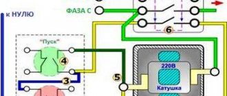
Almost every day we are faced with the same question from our customers: “how to connect an electric motor to the power supply?”
The easiest and most reliable way is to contact a proper electrician and do not skimp on this, because... Often, in an attempt to save money, they invite “Uncle Vasya” or other sympathetic “specialists” who are nearby, but in fact have little understanding of what is happening. At best, these “pros” call and ask if I’m connecting correctly. There is still a chance not to burn the engine. The qualifications of an “electrician” immediately become clear when they ask such questions that you can simply fall into a stupor (since this is exactly what electricians are taught).
For example: - why are there six contacts in the engine? — why are there only three contacts? - What are “star” and “triangle”? — why, when I connect a three-phase pump and install a float switch that breaks one phase, the engine does not stop? — how to measure the current in the windings? — what is a starter? and so on.
If your electrician asks such questions, then you need to send him back to where he came from. Otherwise, everything will end with a burnt out electric motor, loss of money, time, and expensive repairs. Let's try to understand the diagrams for connecting an electric motor to the power supply. First you need to understand that there are several popular types of AC networks:
1. Single-phase network 220V, 2. Three-phase network 220V (usually used on ships), 3. Three-phase network 220V/380V, 4. Three-phase network 380V/660V. There are also voltages of 6000V and some other rare ones, but we will not consider them.
In a three-phase network there are usually 4 wires (3 phases and zero). There may also be a separate ground wire. But there are also ones without a neutral wire.
How to determine the voltage in your network? Very simple. To do this, you need to measure the voltage between phases and between zero and phase.
In 220/380 V networks, the voltage between phases (U1, U2 and U3) will be equal to 380 V, and the voltage between zero and phase (U4, U5 and U6) will be equal to 220 V. In 380/660 V networks, the voltage between any phases (U1 , U2 and U3) will be equal to 660V, and the voltage between zero and phase (U4, U5 and U6) will be equal to 380V.
Operating principle of the electric motor
Together with the batteries, the electric motor forms a system that converts electrical energy into mechanical energy for movement. It is safe to say that it represents the heart of a car or electric vehicle, technical equipment of a wide variety of types.
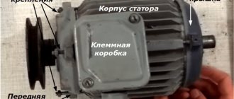
Its design contains a stator, a rotor (can be internal or external), brush-contact and bearing units, and a fan. All this is enclosed in a casing.
For your purposes, you can use different types of electric motors. These can be synchronous and asynchronous motors, single- and three-phase, BLDC type. They have different powers and are designed for different connection and operating conditions.
The electric motor must:
- Be able to develop significant torque starting from zero speed;
- Provide significant peak power to ensure trouble-free operation under extreme loads and power surges in the network;
- Have the simplest possible control system;
- Be light and compact;
- It is relatively inexpensive;
- They have high efficiency;
- Act as a generator when the vehicle slows down.
Therefore, an ideal motor should have excellent characteristics such as high starting torque, high power density and good energy efficiency.
To make the engine work, there are several connection schemes, the most common among them are star and delta.
Regulations
Taking into account the large number of electrical elements, a number of normative documents have been developed for their alphanumeric (hereinafter referred to as BO) and conventional graphic designations (UGO) to eliminate discrepancies. Below is a table showing the main standards.
Table 1. Standards for graphic designation of individual elements in installation and circuit diagrams.
| GOST number | Short description |
| 2.710 81 | This document contains GOST requirements for BO of various types of electrical elements, including electrical appliances. |
| 2.747 68 | Requirements for the dimensions of displaying elements in graphical form. |
| 21.614 88 | Accepted codes for electrical and wiring plans. |
| 2.755 87 | Display of switching devices and contact connections on diagrams |
| 2.756 76 | Standards for sensing parts of electromechanical equipment. |
| 2.709 89 | This standard regulates the standards in accordance with which contact connections and wires are indicated on diagrams. |
| 21.404 85 | Schematic symbols for equipment used in automation systems |
It should be taken into account that the element base changes over time, and accordingly changes are made to regulatory documents, although this process is more inert. Let's give a simple example: RCDs and automatic circuit breakers have been widely used in Russia for more than a decade, but there is still no single standard according to GOST 2.755-87 for these devices, unlike circuit breakers. It is quite possible that this issue will be resolved in the near future. To keep abreast of such innovations, professionals monitor changes in regulatory documents; amateurs do not have to do this; it is enough to know the decoding of the main symbols.
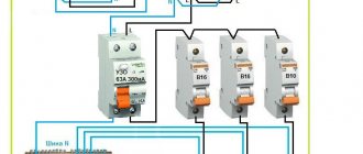
Starting three-phase motors
Star-delta starting is used on three-phase motors equipped with a terminal block with six terminals for the start and end of the winding, allowing both star and delta connections of the motor windings.
Triangle
A delta connection consists of connecting the end of the winding of a given phase to the beginning of the winding of the next phase. The windings connected in this way form a closed circuit and resemble a triangle in appearance.
Then the common points of the windings are connected to the next phases of the supply network. This connection does not use a neutral point at all. In a delta connection, each winding has a line-to-phase voltage, typically 400 V.
- When the motor windings are delta-connected, the current drawn by the motor from the mains is 3 times the current drawn in a star connection. In addition, the electromagnetic torque and therefore the motor power is three times higher in this case.
- Using a star-delta switch, we can start a star-connected motor, which will reduce the current draw from the mains, and then when the motor reaches the appropriate rotation speed, the stator windings need to be switched to delta so that the motor can provide the required power.
- In older solutions, switching was usually done manually by an operator; nowadays, special contactors and relay systems are used for this purpose, which switch automatically after a specified time.
The triangle connection of the motor windings must correspond to the rated voltage of the supply network. When the motor is powered from a three-phase network with a rated voltage of 400 V, the connection of the windings in a triangle corresponds to a voltage of 400 V, and when connected by a star, the supply voltage is reduced by the root of three. This means that when connected by a star, the voltage will be 1.7 times lower than the rated voltage of the supply network.
Star
A star connection is the connection of the ends of all three windings with one common point, and the remaining three ends with successive phases of the supply network.
Thus, each of the stator windings is connected at one end to the neutral wire (neutral), and at the other end to the phase wire.
Therefore, each of these windings has a phase voltage. It is not usually used to connect all windings to the neutral as this is not necessary.
- The starting torque of a three-phase star-connected motor is significantly less than that of direct starting, approximately 50% of the rated torque.
- Starting with a reduced supply voltage and therefore a reduced starting torque also causes a reduction in the starting current, which is usually in the range of 1.8 to 2.6 times the rated current depending on the type of motor and type of load.
- A significant limitation in the use of this method is the low starting torque, so this method can only be used when the mechanical load of the motor during starting is small, or the load is increasing at a higher speed close to the rated speed. speed.
- This load is typical for fans, pumps and centrifuges.
Operating principle
The principle of operation of an electric motor demonstrates the simplest experiment that we were all shown at school - the rotation of a frame with current in the field of a permanent magnet.
The frame with current is an analogue of the rotor, the stationary magnet is the stator. If current is applied to the frame, it will turn perpendicular to the direction of the magnetic field and freeze in this position. If you force the magnet to spin, the frame will rotate at the same speed , that is, synchronously with the magnet. We have a synchronous electric motor. But our magnet is a stator, and by definition it is motionless. How to make the magnetic field of a stationary stator rotate?
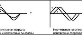
First, let's replace the permanent magnet with a current-carrying coil. This is the winding of our stator. As is known from the same school physics, a coil with current creates a magnetic field. The latter is proportional to the magnitude of the current, and the polarity depends on the direction of the current in the coil. If we apply alternating current to the coil, we get an alternating field.
Magnetic field is a vector quantity. The alternating current in the supply network has a sinusoidal shape.
A very clear analogy with a clock will help us. What vectors constantly rotate before our eyes? These are the hour hands . Let's imagine that there is a clock hanging in the corner of the room. The second hand rotates one full revolution per minute. An arrow is a vector of unit length.
The shadow that the arrow casts on the wall varies as a sine with a period of 1 minute, and the shadow cast on the floor changes as a cosine. Or a sine phase shifted by 90 degrees. But a vector is equal to the sum of its projections. In other words, the arrow is equal to the vector sum of its shadows.
Selecting a connection diagram
If necessary, especially if you need to switch from 380V to 220V, the connection diagram can be changed. When the speed is close to the rated speed, the winding should be switched in a delta pattern.
- Switching the windings from star to delta too early will eliminate the benefits of this starting method.
- In this case, there will be a sharp jump in the current value to the characteristic value of the triangle. If the start time is correct, this move is minimal.
- The star-delta switch for higher power motors consists of three contactors and a time relay on which we set a time delay followed by delta switching and powering the motor with full mains voltage.
- This starting is only possible for 3-phase motors that have 6 terminals on the terminal block.
An electrical system with three terminals (in other words, "has three legs") is called a tee because this connection results in a system with three electrical terminals.
How to select capacitors?
If you are planning to connect an electric motor, then the choice of capacitor is carried out according to the following principles:
- The rated voltage is selected from the ratio of 1.15 of that supplied to the motor. If the brother is larger, this will increase the cost of the installation and its dimensions. If the capacitance is calculated back to back, the capacitor will overheat and burn out.
- Type of capacitor - the most common models are paper, but they are large in size. Therefore, it is more profitable to purchase polypropylene ones. It is better to avoid electrolytic ones.
- To select the capacitance of the starting and running capacitors, you must use the correspondence table for electric motor power:
Table: determination of capacitor capacity
| Three-phase electric motor power, kW | 0,4 | 0,6 | 0,8 | 1,1 | 1,5 | 2,2 |
| Minimum capacitance of the capacitor Ср, µF | 40 | 60 | 80 | 100 | 150 | 230 |
| Starting capacitor capacity (Cn), µF | 80 | 120 | 160 | 200 | 250 | 300 |
If the power you need is not in the table, you can use the calculation formulas:
Serb = (2800*I)/U - to turn on a three-phase motor with a star
Crab = (4800*I)/U - to turn on a three-phase motor with a triangle
where I is the amount of current flowing through the windings of the electric motor, and U is the network voltage. To find out the capacity of the starting capacitor for connecting a three-phase unit, you need to multiply the resulting working value by two.