History of development and advantages of application
Hydraulic sheet bending, which began to be used by manufacturing enterprises in the middle of the 20th century, replaced manual and mechanical devices designed for bending sheet metal. Along with the high efficiency and cost-effectiveness of use, the manual bending press also has a number of significant disadvantages, primarily associated with the impossibility of obtaining products with precise geometric parameters with its help, as well as with the application of significant physical effort when using it.
Mechanical press brakes are also not without their disadvantages, which are as follows:
- The operation of such a machine is accompanied by significant noise and strong vibration.
- Products made using such equipment are not of high quality.
- When operating such a machine, the risk of injury to the operator operating it is too great.
- The use of such a press brake is associated with increased energy consumption.
- Re-adjusting mechanical ones is a rather complex procedure.
In addition to mechanical and manual ones, press brakes with pneumatic drive are also available on the modern market. Such equipment, the operation of which requires a centralized compressed air network, has one very serious drawback: even with an increase in the size of the machine, the force it develops, with which it acts on the workpiece being processed, does not allow processing of sheet metal products of significant thickness.
Having appeared on the market, the hydraulic sheet bender, characterized by the highest power among all equipment for this purpose, made a real breakthrough in the processing of sheet metal by bending. This press bender, in addition to high power, has many other advantages:
- high level of security;
- high reliability;
- the ability to produce products of exceptionally high quality.
Having appeared on the market in the middle of the 20th century, hydraulic models of sheet bending machines acquired a number of significant improvements, which made it possible to provide these devices with additional functionality and make them more convenient and safe to use. Equipping a modern hydraulic press brake with innovative devices and additional mechanisms allows it to be used to successfully solve even the most complex problems associated with sheet metal bending. Among such devices and mechanisms are:
- CNC system for a press brake (such a system, equipped with a graphical user interface, is able to independently determine the modes and sequence of technological operations);
- mechanisms that provide increased protection for the machine operator from injury;
- electronic devices that are responsible for adjusting the speed of movement of the traverse;
- indicator that provides control over the angle of bending being performed.
This is just a small list of additional elements that may be present in the design of a hydraulic press brake. The presence of such equipment significantly expands the functionality of the machine and makes it possible to use it to solve special problems.
Design Features
A press bender equipped with a hydraulic drive is used to solve the following technological problems:
- formation of bent metal products, the geometric parameters of which exactly correspond to the specified parameters;
- performing one of the stages of the technological process of processing products made of sheet steel, the thickness of which exceeds 3.5 mm;
- performing high-quality and inexpensive bending of sheet steel products, the thickness of which does not exceed 3.5 mm;
- production by bending of large batches of the same type of sheet steel products.
According to the degree of its mobility, a hydraulic sheet bender can be mobile or stationary. Stationary metal bending presses equipped with a hydraulic drive are characterized by high power and productivity. They are used to process a large number of workpieces in a limited period of time. In addition, stationary hydraulic sheet benders, due to their technical capabilities, are successfully used for processing workpieces made of sheet metal, even of very significant thickness. Mobile or mobile presses, also powered by a hydraulic drive, can be easily moved to any site where they are planned to be used for their intended purpose.
The operating principle of a press brake is that its working body, which is a traverse, is informed of the required direction of movement and the level of force with which it acts on the workpiece being processed. The traverse is a rigid beam made of steel. It is on it that the working devices are fixed, with the help of which the product is formed with the given geometric parameters.
Two linear sensors are responsible for the accuracy of the movement of the traverse, on which the accuracy and quality of the processing performed directly depends, one of which monitors the right side of the working element, and the second monitors the left. In order to enable the bending edge to be formed with the required geometric parameters on hydraulic sheet bending machines, most models are equipped with a rear programmable stop. Hydraulic sheet benders are practically indispensable equipment in the production of products for the following purposes:
- case parts for household and industrial equipment, electrical devices for various purposes;
- elements of vehicle bodies;
- bent metal products for any other purpose.
Using special bending tools for press brakes, such equipment can successfully process sheet metal blanks with cylindrical and conical configurations.
Principle of operation
The principle by which a press brake equipped with a hydraulic drive operates is quite simple, but nevertheless ensures both high productivity of technological operations and their safety.
The process of bending sheet metal blanks when using a machine of this category is performed in the following sequence:
- The press crossbar is fixed at the “dead center” of the sheet bending equipment, located in its upper part.
- In order for the traverse to begin to move from top to bottom at the required speed, a foot pedal or button is used to control this mechanism. Up to a certain position, the traverse moves at a free fall speed, which is higher than the speed required for bending. Despite this definition, there is no free fall of the traverse as such; each of its movements is monitored and controlled by means of appropriate equipment.
- When the traverse is as close as possible to the surface of the workpiece being processed, the working speed is imparted to the beam. All movements of the traverse, as well as the operating modes of such movements, are controlled by the hydraulic system of the press brake, and hardware control devices or special sensors are responsible for controlling such processes.
- The traverse of the machine, after imparting operating speed to it, tends to the bottom “dead point”, after reaching which it is maintained in this position for some time. Holding the traverse at the bottom “dead center” is necessary in order to ensure a uniform load on the surface of the workpiece that is undergoing the bending process.
- It is very important, after finishing bending the workpiece, to begin lifting the traverse at a certain speed, which has no less influence on the quality of the processing performed than the process of its implementation itself. The stage of the bending process, at which the traverse rises above the surface of the newly processed workpiece, is called decompression.
- After decompression is completed, the traverse returns to the top “dead center” at a sufficiently high speed.
- The equipment is turned off and the finished product is removed from the processing area.
The technological process of bending a sheet metal workpiece, carried out on a press brake equipped with additional working mechanisms, may differ slightly from the scheme described above, but in general its essence remains unchanged.
When processing workpieces on a hydraulic sheet bending machine, we are guided by several basic parameters of both the equipment used and the technological process. Such parameters, in particular, include:
- working length of the equipment used;
- the force that the working body of the press exerts on the workpiece being processed;
- the productivity with which processing is performed.
In addition to the main ones, there are also a number of additional parameters that also need to be taken into account both when choosing a press and when performing processing. These parameters include:
- distance between the side posts of the machine;
- the speed at which work operations are performed;
- the maximum distance the traverse can be raised, etc.
Steps to set up a press brake.
Standardization of Operating Procedures.
Metalworking companies today are often faced with the need to produce small series of parts, and with more stringent tolerance requirements of their customers. Implementing standard operating procedures for press brake setup and tooling during the job goes a long way toward achieving consistency in producing high-quality parts with minimal waste.
For repetitive jobs, implementing Press Brake Setup Sheets can help achieve consistency and efficiency as they incorporate previous best practice experience, help avoid errors, omissions, and improve efficiency since each operator does not have to figure it out from scratch every time. Press Brake Setup Sheets may include a list of required tools, setup sequence, installations, and other job-specific information.
The Press Brake Setup procedure may contain these 7 steps:
1. Study the drawing carefully: This should be done the first time this job is run on the press brake and then used for reference on subsequent repeat runs. The main things for bending metal: thickness of the material and its type, dimensions and tolerances, metal bending angles, internal radii, etc. Many drawings do not indicate the internal bending radius of the metal, but this is very important in determining the type of equipment required in some cases for a press brake. 2. Select the equipment and tools of the press brake, depending on the type of metal bending used. 3. Determine the weight requirements based on the metal bending method selected in the previous step. 4. Set the press brake tooling position, centered or eccentric, as appropriate, and make the necessary changes. This step is usually the most labor intensive, but it is the effort required to achieve the required accuracy. 5. Set the program parameters for the press brake control system. This operation is another point of potential efficiency improvement, as this step can be time consuming; But by spending a little time on training, especially on the most complex functions of the press brake, this time can be significantly reduced. 6. Perform a test bend of the metal and make the necessary changes to the press brake settings. Whenever possible, use scraps or scraps to save on material costs. A properly trained press brake operator can make adjustments quickly and efficiently. Once the metal bending is well formed, do not make any further adjustments to the press brake settings. 7. Begin bending the metal, but allow enough time between press brake tooling cycles to ensure the part continues to be produced to proper tolerances.
Using standard press brake setup procedures, ensuring operators are properly trained in both equipment knowledge and metal bending technology, can mitigate the negative impact of increasing raw material prices, and ensure complex press brakes are operated accurately and efficiently. Combining the human skill to use the advanced control functions found in today's press brakes with process optimization will result in greater productivity and reduced scrap and waste.
Brief description of the LGSG-28 model
In the equipment of many manufacturing enterprises whose activities involve the need to bend sheet metal blanks, one can find the LGSG-28 model for bending, manufactured by the Lipetsk plant for the production of special roll forming equipment. The technical capabilities of such a press make it possible to successfully use it for bending sheet metal blanks, the thickness of which reaches 3 mm and the length up to 2.5 m.
The most appropriate use of a machine of this model is for those enterprises that are engaged in the production of the same type of metal products in medium and large series. Of the most significant advantages of the press brake of this model, the following should be highlighted:
- low noise level emitted during operation of the device;
- ease of management and maintenance;
- optimal combination of functionality and cost;
- economical energy consumption;
- the ability to perform bending both manually and fully automated;
- high versatility;
- high reliability, availability of spare parts and components for maintenance and repair.
The hydraulic equipment equipped with the press of this model allows the development of force in the bending area, reaching a value of 20 tons. The maximum bending angle that such equipment can achieve is 105°, and it can be performed at a minimum width of 4 cm.
CNC machines
Recently, hydraulic press brakes have become very popular, equipped with a numerical program unit responsible for controlling the device. Such equipment, which can be a sheet bending machine with a rotary beam, or any other type of machine, allows you to perform technological operations with high accuracy and productivity.
CNC sheet bending machines produced in Portugal under the Adira brand have gained great popularity among domestic manufacturers due to their reliability and wide functionality. The CNC hydraulic press brake of this brand is presented on the domestic market with models of varying power and functionality, but they all have the following advantages:
- durable traverse, made in monoblock design;
- compact dimensions of hydraulic equipment installed on machines;
- the presence of two types of overload protection: hydraulic and electrical;
- the presence in the design of the machine of two servo valves, which are controlled automatically;
- ease of setup of all operating modes;
- high performance and Russification of the controllers installed on this CNC sheet bending machine;
- powerful design of the back stop, equipped with four controlled axes.
The first machines designed for bending sheet metal were invented back in the 19th century in America. At this time, an industrial boom began in the world, which was characterized by the widespread introduction into production of all kinds of machines and mechanisms. The widespread use of sheet metal bending machines was due to the high labor intensity of manual production of sheet metal parts. The first such machines were mechanical and had very low productivity.
After the invention of the high-pressure cylinder, the development of various machines operating on the basis of pneumatic pressure began. This principle was also applied in new designs of metal bending machines. However, such machines were too bulky and inconvenient to use. It was only in the middle of the 20th century that the first hydraulic sheet benders were designed. As practice has shown, such a system turned out to be the most effective and technologically advanced to use.
Features of bending sheet metal on press brakes.
There are several methods for bending sheet metal. In this article we will look at the most universal and common method of producing three-dimensional products from sheet metal using hydraulic press brakes with a vertical bending beam.
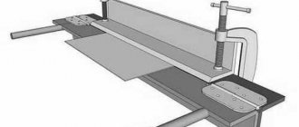
The main technological tasks of the bending process are to ensure the accuracy of the angle, radius at the bending point and the size of the part flanges within the specified tolerances. The part is installed on the matrix and positioned horizontally against the stops, determining the size of the shelf (Fig. 1).
The bending angle is ensured by the depth of penetration of the punch into the matrix, which presses the workpiece into it (Fig. 2). The radius is determined by the radius of the punch and the distance between the edges of the die (when it is opened).
It is necessary to understand that bending parameters, such as force, punch penetration depth, die opening, etc., are directly influenced by the mechanical properties of the material, thickness and bending depth. This is especially important if the properties and thickness of the metal have large deviations even in one delivery batch.
To obtain a given angle and radius, several bending methods are usually used, each of which has its own advantages and disadvantages. With regard to all methods of providing angle and radius, we can say that an important issue is the selection of tools. It is the shape and dimensions of the punch-die setup that make it possible to obtain different angles and radii at certain thicknesses, flange sizes and bending lengths, along with the capabilities of the presses. A detailed description of each bending method could be the topic of several articles, so we will focus on the main points of the first two methods: the air bending method and the adaptive method.
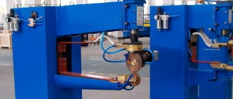
In order to move on to a description of the equipment used to ensure these processes and its features, we will consider the general design of press brakes and the principles of their operation, the axes of movement and their designations (Fig. 3). The hydraulic press brake consists of the following elements:
- hydraulic cylinders that are attached to the side posts;
- lower beam with table and matrix fastening system;
- an upper beam with a system for fastening punches attached to the hydraulic cylinder rods;
- systems of back stops that provide support for the workpiece and are installed on the rear side of the lower beam
The hydraulic cylinder rods impart movement to the upper beam in a vertical direction along the Y axis, thereby ensuring the depth of penetration of the punch into the matrix. The back stops can move along three axes X, R, Z, namely depth, height relative to the bend line and along the bend line, respectively (Fig. 4).
The V axis determines the amount of compensation for deflection of the press beams. The press can be equipped with a front support device for the sheet with the ability to accompany it during bending, to determine the movements of which the T axis is used. The W axis determines the movement of the non-contact adaptive angle control device along the bending line. Press brakes can be divided into three categories based on the way the axes move and control their positions:
- all axes are positioned manually;
- presses are controlled by CNC;
- CNC presses.
When choosing presses belonging to the first two categories, it can be argued that the company plans to purchase a budget solution to its problems, while flexibility, versatility and speed of transition from one product to another are not selection criteria.
Let's look at CNC press brakes in more detail, because... It is this type of equipment that raises a large number of questions during the selection process.
The issue of choosing presses is an important task for enterprises. The selection criteria can be very different, based on the actual production tasks and the size of the planned investment. We will consider this issue only from the point of view of equipment capabilities. The movement of the upper beam along the Y axis is determined by the force developed, the approach speed, the working stroke and the return speed. These parameters primarily affect performance. Y-axis positioning accuracy is the most important parameter because it directly affects the bending angle. Almost all manufacturers control this parameter by installing optical rulers on the side stands of the press. The accuracy of this parameter must be ensured within 0.01 mm, because a change by this amount already creates an error of 1* at a bend angle of 135* (die opening 4 mm). The larger the angle and the smaller the thickness, the greater the impact on the accuracy of the angle is the position accuracy along the Y axis. The issue of quality control of the movement of the upper beam is directly related to the movement of the rods of the left and right hydraulic cylinders. In this sense, on CNC presses there are two Y axes - Y1 and Y2. Ensuring synchronization of movements and positioning is an important task for press manufacturers. If there is a position difference, then the angle of the part along the bend length will be different. You can also programmatically set the skew of the top beam if you want to get different angles on the left and right sides of the bend line.
Speaking about the movement and positioning of the upper beam, it is necessary to note two more possibilities of the press. Firstly, this is the time of delay and retention of the force at the bottom point, which affects the fixation of the angle and in many cases is important for automatic control and correction of the angle during adaptive bending. Secondly, this is compensation for the opening of the side racks of the press during the force position. Almost all manufacturers equip their machines as standard with brackets with limit switches for this correction.
The V axis, which determines the compensation for the deflection of the beams, ensures a constant angle along the entire length of the bend. When the force of the upper beam is applied along the Y1 and Y2 axes, the upper and lower beams deflect from the middle to the sides. The result is different angles along the bend line. To optimize this effect, manufacturers use various deflection compensation systems or “bombing” systems. The wedge system is based on the displacement of the upper part of the table relative to the lower, where the angle of the wedges decreases from the center of the table to its edges (Fig. 5).
The wave system is similar to the wedge system, but instead of wedges, a wave profile is used. A system of specially shaped cutouts in the bottom beam is also offered, which are designed to compensate for any effects of deflection of the beams. Another option is a system of hydraulic cylinders built into the bottom beam.
Deflection compensation systems can be manually set or CNC controlled. CNC systems make it possible to automate this process and store permanent data in memory for certain materials, thicknesses, and parts. For bending lengths greater than 2000 mm, the use of a deflection compensation system is a necessary condition for obtaining a constant angle along the entire length of the part.
When considering the movements of the upper beam and beam deflection compensation systems, we talked about the position of the bottom point of the punch. The positions of the back stops along the X, R, Z axes provide a base for the workpiece to determine the dimensions of the part shelves. The choice of the design of the back stops and the number of CNC controlled axes depends on the complexity of the parts being produced. For these purposes, equipment manufacturers offer many options. The simplest is the double movement of two stops along the X axis (X1+X2) and manual adjustment of the stops along the R1, R2 and Z1, Z2 axes. This arrangement of stops is effective in the manufacture of simple parts that do not require mounting at height. The CNC scheme of double movement of the stops along X and R with manual movement along Z1, Z2 allows you to automatically position the stops, both in depth and in height. Another option is to add CNC movement along the Z1 and Z2 axes and at the same time eliminate the loss of time for manually moving the stops along the bending line. It is also possible to select CNC movement along the partial X or X` axis of one of the stops and provide the ability to base the workpiece at a slight angle. Full versatility can be achieved by using independent two stops with each of them moving along three axes X1, R1, Z1 and X2, R2, Z2. The choice of stop pattern depends on the need to base the workpiece at an angle or when choosing independent movement along the X1, X2 axes.
Any material has a certain spring coefficient and tends to take its original shape. With free bending, at the moment the force is removed, the angle opens and must be adjusted. Typically, the operator's actions when putting a part into production consist of the first bend, measurement of the resulting angle, entering a correction for the difference in angle, the next bend, a new measurement of the resulting angle, etc. until the task is received. Each time the operator introduces a correction for changing the positions of the Y1, Y2 axes and the beam deflection compensation axis.
The problem of obtaining a given bending angle the first time is relevant and there are several options for solving it. It is necessary to determine selection criteria or requirements for such devices. The system must have a high-speed CNC interface so as not to slow down the bending process. In addition, it must be installed so as not to interfere with the bending process; It is necessary to ensure the possibility of bending short shelves and Z-profiles. The system must be functional when working in difficult production conditions and not depend on the accuracy of tooling, as well as on the variability of the quality of the metal being processed (changes in thickness, hardness, structure direction). Manufacturers offer several solutions.
Laser control of the bending angle is based on the projection of many laser points onto the part shelf and the surface of the matrix (Fig. 6) using radiation cameras installed on both sides of the lower table.
The measurement result is an angle obtained in real time. The measurements are transmitted to the CNC, and the angle is adjusted automatically by changing the positions of the Y1, Y2 hydraulic cylinders and the V axis of deflection compensation. The device has the ability to move along the bending line, thereby providing measurements in the center and along the edges of the part. The system operates in two modes: angle control based on the amount of springback programmed into the CNC, and measurement of springback, saving data for further use in the production of parts from this material.
There is another system based on the use of mechanical sensors built into special segments of the tooling. The angle is also measured here and corrected based on data received from the built-in sensors. Special tool segments and their installation at the measurement locations are required. There is another system that does not use the principle of directly measuring the angle in real time, but uses precision pressure measurement in the hydraulic system and calculates the angle value based on the position of the punch at the lowest point.
Heavy press brakes with a capacity of 300 tons and above to 3000 - 5000 tons and tandem press brakes deserve special attention (Fig. 8). There are few manufacturers of such machines, since implementing on these machines all the requirements that we discussed above is a rather complicated task. If it is necessary to provide a bending depth of 10 m or more, the choice is usually made to use tandem presses. This use involves the use of two presses operating synchronously. In this case, presses can have different bending lengths and different forces. The total force will be calculated based on the lesser force per meter of glib length. The advantage of this scheme is that the presses can be used both in synchronous operation mode and each machine separately. At the same time, the investment in a tandem solution (for example, two 6 m presses with a force of 640 tons each) is less than in one press (with a bending length of 12 m and a force of 1280 tons).
In conclusion, we give the names of manufacturers of hydraulic press brakes that operate on the market of Russia and the CIS countries independently or through their dealers: LVD Company NV (Belgium), Trumpf (Germany), EHT (Germany), Amada (Japan-France), Finn -Power (Finland), Bystronic (Switzerland), Darley (Holland), Gasparini (Italy), Vimercati (Italy), Colgar (Italy), Schiavi (Italy), Aliko (Finland), Adira (Portugal), Haco (Belgium) , Ermaksan (Turkey), Durma (Turkey), Baykal (Turkey), MVD (Turkey).
Information about these companies can be found on the Internet, request commercial offers, compare offers and consult with company representatives. We hope this article will help you analyze the equipment according to the main criteria and make the right choice.
Vladimir Polkovnikov, Director of the Sheet Metal Processing Equipment Department, Weber Comechanics LLC [email protected]
Scope and varieties
At its core, a sheet bending machine is a press designed for bending various sheet metal blanks. The advantage of bending using a machine is the absence of metal deformations, which are inevitable when bending manually using a mallet. The bending beam is usually equipped with rubber pads, which ensure the safety of the surface when working with painted sheets.
A hydraulic sheet bender can bend sheets of tin, copper, aluminum, and also steel. This achieves very high bending accuracy. Such machines are mainly used to produce metal parts for roofing and exterior finishing of buildings - slopes, ridges, external and internal corners. Sheet benders are also used in the automotive, aviation, and shipbuilding industries - wherever a person deals with sheet metal.
Modern sheet benders come in three main types:
- Manual. In such bending machines, the worker’s muscular force is used, transmitted through a system of blocks to the mechanism.
- Electrical. In them, work is carried out using electric motors.
- Hydraulic. The most common type. It operates using fluid energy supplied from high pressure cylinders.
Often machines are equipped with auxiliary devices that increase the range of their functions. For example, metal roll holders; a square to set the bending angle; additional supports for sheets. The machine is also often equipped with a roller knife for cutting metal sheets.
The hydraulic sheet bender can be equipped with software. Such machines, equipped with CNC (computer numerical control) provide higher productivity. CNC sheet bending machines can be programmed to produce all kinds of parts automatically.
Modern devices can not only read drawings and perform bending independently, but can even be equipped with equipment similar to that installed on 3D printers. Thus, the latest CNC devices can bend three-dimensional parts and workpieces. The cost of such machines varies greatly - from tens of thousands for mechanical ones, to several millions for complex hydraulic machines with electronic control. In the photo you can see different types of sheet benders.
Today, almost any metalworking enterprise regularly faces the need to produce small batches of parts (medium or small-scale production), but with fairly stringent requirements for the quality of the manufactured goods. If you implement the standard operating procedures required to set up press brakes, it can take quite a long time to achieve consistency to the required quality to produce the required product while incurring minimal costs in consumables and process waste.
If production tasks are repeated with some frequency, then it is rational to introduce setting sheets for press brakes, which will allow all setting operations to be carried out with minimal time and achieve the highest results in terms of quality. Such setting sheets, as a rule, already contain some best practical experience, which has a positive effect on overall work efficiency; the risk of defects is reduced, because the machine operator no longer needs to deal with each new part and technological process from scratch. It is also worth noting that setup sheets for press brakes usually also include a set of required tools, step-by-step instructions for setting up the equipment and various other information necessary for quality work.
Press brake setup process.
This is a difficult, but very important process in the entire technological process, since the quality of the manufactured parts depends on it. Setup can be done in simple but quite effective steps:
- The first thing you need to do is to study with special care the drawing presented for the manufacture of the part. This step is necessary if this is your first time producing the required part on a press brake. In the future, when manufacturing identical parts, this step can be skipped using the previously obtained information. The most important information that you need to obtain after reading the drawing is: the type of material and its thickness, bending angles, tolerances and dimensions, internal radii, etc. There are drawings where the internal radius is not indicated, although this parameter is decisive for obtaining a high-quality part, since on the basis of it the necessary equipment is selected (if there is such a need).
- In the future, it is necessary to select tools and equipment for the work (this depends on the type of bending and the metal being processed).
- We determine the weight requirements based on the information obtained from step two of the bending method.
- We install the press brake equipment in an eccentric position or in the center and make the necessary changes. This step is considered the most time-consuming, but with the appropriate approach, all efforts are compensated by high precision in the manufacture of the part.
- We proceed to setting up the program, setting the necessary parameters for controlling the machine. This step also leads to increased overall efficiency, especially if done correctly. The process is quite labor-intensive and time-consuming, but properly trained personnel can reduce it significantly, especially when it comes to the most complex press brake control functions.
- The next step involves performing a test bending operation after which it is necessary to make certain adjustments to the settings, if any are required. If possible, it is best to use waste or defective workpieces for this operation, which will reduce economic costs. If the press brake operator is professionally trained, he can make adjustments to the settings without much effort. Once you have achieved the desired results after bending, try not to make any further adjustments.
- Now you can begin manufacturing the main batch of parts, but before that it is better to set a slightly longer time interval between cycles, as this will allow you to more carefully control the process of the machine and monitor the fulfillment of all tolerances.
By optimizing the work process and using qualified personnel who have a set of specific knowledge and are able to apply them in practice, it allows us to ensure high productivity, while reducing the percentage of defects and waste.
By contacting, you can choose press brakes with exactly the characteristics that are necessary for your production. The company's consultants will help with any questions, making the purchase and selection process as comfortable as possible. Call and come, we welcome everyone!
Principle of operation
The operating principle of any such machine - be it a simple manual mechanism or a complex electronic CNC machine - is the same. It consists of a base - a frame, on which a massive flat metal sheet is attached (the so-called “traverse”), which serves as a table for attaching all other machine mechanisms - clamping devices, a rotating beam, a knife for cutting metal, etc.
The sheet fed onto the traverse is fixed in the desired position by clamping devices and bent to the desired angle using a rotating beam. Fixing the sheet can be done either manually on machines of the simplest designs, or using an electronically controlled mechanism on CNC machines. The maximum thickness of a sheet of metal that can be bent by the machine depends on its power and can reach several millimeters.
Do-it-yourself sheet bender
Often on the farm there is a need to bend a sheet of metal. However, doing this with the help of available materials (hammer, vice, mallet, etc.) can be difficult. You won't be able to get a perfectly even bend using this method. It is not practical to purchase an expensive machine just to use it on the farm from time to time. The only way left is to make such a mechanism with your own hands. The most technologically advanced way is to build it on a workbench. To do this, you will need three pieces of metal corner. Their length is calculated so that you can bend a sheet of the width you need.
Next, we take a pair of fairly massive hinges, and by welding these hinges we connect two corners with shelves facing each other, so that they “open” like doors. This will be the main mechanism of our future machine - a traverse and a rotary beam. We make holes along the edges of one of them - clamps will pass through them, with which our traverse will be attached to the workbench and to the pressure beam - the third section of the angle (it will press the sheet of metal to the traverse). We weld scraps of reinforcement to the edges of the other corner - these will be handles, with the help of which we will set our “rotating beam” in motion. In the third corner (“pressure beam”) we make holes exactly opposite the same holes in the corner - the traverse. Then, using anchor bolts or clamps threaded through the “pressure beam”, “crossbeam” and the outer board of the workbench, we fix our mechanism. That's it - our home sheet bender is ready. It is enough to insert a sheet of metal between the traverse and the pressure beam. Then tighten them with clamps or bolts and lift up the “rotating beam”, hingedly connected to the stationary “crossbeam”, to get an ideal bend, in no way inferior to the factory one! Step-by-step instructions on how to assemble a simple machine for bending metal sheets at home are presented in the video.
Hydraulic sheet bending is used at various production enterprises for bending sheet metal using a cold method with strict adherence to specified bending angles.
Changing bend radius
When working on a Decker X5 sheet bender, you can increase the bending radius of the processed sheet of metal. This can be done by lowering the bending beam downwards. The lower the level of the bending beam, the larger the bending radius. To set the minimum radius, the bending beam must be adjusted as follows: its upper plane must be the thickness of the metal being processed below the level of the main one. The minimum bending radius cannot be less than the thickness of the workpiece. This adjustment is made at the edges of the bending beam.