The dream of finding treasure is increasingly being replaced in our time by a more realistic program of searching for precious metals in a natural or artificial environment.
In modern conditions, it is very important to find and extract valuable materials found among waste , garbage or other uncontrolled environments.
Equipment is an important component of such search technology.
The search and extraction of gold and valuable metals from waste, garbage, in the natural environment is part of the recycling strategy, a technology for the effective processing of used materials, including the processing of precious metals.
Searching for them in the ground or in masses of industrial and other waste not only requires the use of equipment, but also stimulates its improvement. Devices of different levels and specializations are being created . There is interest in such equipment among amateurs and enthusiasts of searching for valuable metals.
Metal detector N. Martynyuk
The metal detector according to N. Martynyuk’s scheme (Fig. 1) is made on the basis of a miniature radio transmitter, the radiation of which is modulated by an audio signal [Рл 8/97-30]. The modulator is a low-frequency generator made according to the well-known symmetrical multivibrator circuit.
The signal from the collector of one of the multivibrator transistors is fed to the base of the high-frequency generator transistor (VT3). The operating frequency of the generator is located in the frequency range of the VHF-FM broadcast range (64... 108 MHz). A piece of television cable in the form of a coil with a diameter of 15...25 cm was used as the inductor of the oscillating circuit.
Rice. 1. Schematic diagram of N. Martynyuk’s metal detector.
If a metal object is brought closer to the inductor of the oscillating circuit, the generation frequency will noticeably change. The closer the object is brought to the coil, the greater the frequency shift will be. To record frequency changes, a conventional FM radio receiver is used, tuned to the frequency of the HF generator.
The receiver's automatic frequency control system should be disabled. If there is no metal object present, a loud beep is heard from the receiver's speaker.
If you bring a piece of metal to the inductor, the generation frequency will change and the volume of the signal will decrease. The disadvantage of the device is its reaction not only to metal, but also to any other conductive objects.
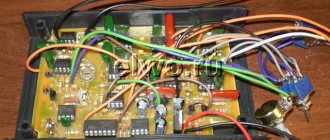
DIY Terminator 3
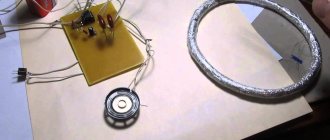
If you need a homemade metal detector with metal discrimination, pay attention to this model. The scheme is quite complicated, but your efforts pay off with the coins you find, which may turn out to be gold.
The peculiarity of the “Terminator” is the separation of the receiving and transmitting coils. A 200 mm ring is made to emit the signal. 30 turns of wire are laid for it, then it is cut, as a result we get 2 half-coils with a total capacity of 60 turns (see diagram).
The receiving coil is located inside, 48 turns with a diameter of 100 mm.
The adjustment is made using an oscilloscope; after achieving optimal amplitude results, the windings are fixed in the housing by pouring epoxy resin.
Then an experimental hands-on adjustment of the discrimination switch is performed. For this, real objects made of various metals are used, and their type is marked on the mode switch (after verification).
Radio amateurs are working on an improved version of Terminator 4, but there is no practical copy yet.
Metal detector based on a low-frequency LC generator
In Fig. 2 - 4 shows a circuit of a metal detector with a different operating principle, based on the use of a low-frequency LC oscillator and a bridge frequency change indicator. The search coil of the metal detector is made in accordance with Fig. 2, 3 (with correction of the number of turns).
Rice. 2. Metal detector search coil.
Rice. 3. Metal detector search coil.
The output signal from the generator is fed to a bridge measuring circuit. A high-resistance telephone capsule TON-1 or TON-2 is used as a bridge null indicator, which can be replaced with a pointer or other external alternating current measuring device. The generator operates at frequency f1, for example, 800 Hz.
Before starting work, the bridge is balanced to zero by adjusting the capacitor C* of the oscillating circuit of the search coil. The frequency f2=f1 at which the bridge will be balanced can be determined from the expression:
Initially, there is no sound in the telephone capsule. When a metal object is introduced into the field of the search coil L1, the generation frequency f1 will change, the bridge will become unbalanced, and a sound signal will be heard in the telephone capsule.
Rice. 4. Diagram of a metal detector with an operating principle based on the use of a low-frequency LC generator.
Metal detector bridge circuit
The bridge circuit of a metal detector using a search coil that changes its inductance when metal objects approach is shown in Fig. 5. An audio frequency signal from a low-frequency generator is supplied to the bridge. Using potentiometer R1, the bridge is balanced for the absence of an audio signal in the telephone capsule.
Rice. 5. Bridge circuit of a metal detector.
To increase the sensitivity of the circuit and increase the amplitude of the bridge unbalance signal, a low-frequency amplifier can be connected to its diagonal. The inductance of the L2 coil should be comparable to the inductance of the L1 search coil.
Metal detector based on a receiver with the CB range
A metal detector operating in conjunction with a mid-wave superheterodyne radio broadcast receiver can be assembled according to the circuit shown in Fig. 6 [R 10/69-48]. The design shown in Fig. 1 can be used as a search coil. 2.
Rice. 6. A metal detector operating in conjunction with a superheterodyne radio receiver in the CB range.
The device is a conventional high-frequency generator operating at 465 kHz (the intermediate frequency of any AM broadcast receiver). The circuits presented in Chapter 12 can be used as a generator.
In the initial state, the frequency of the HF generator, mixing in a nearby radio receiver with the intermediate frequency of the signal received by the receiver, leads to the formation of a difference frequency signal in the audio range. When the generation frequency changes (if there is metal in the field of action of the search coil), the tone of the sound signal changes in proportion to the amount (volume) of the metal object, its distance, and the nature of the metal (some metals increase the generation frequency, others, on the contrary, lower it).
A simple metal detector with two transistors
Rice. 7. Scheme of a simple metal detector using silicon and field-effect transistors.
The diagram of a simple metal detector is shown in Fig. 7. The device uses a low-frequency LC generator, the frequency of which depends on the inductance of the search coil L1. In the presence of a metal object, the generation frequency changes, which can be heard using the BF1 telephone capsule. The sensitivity of such a scheme is low, because It is quite difficult to detect small changes in frequency by ear.
Principle of operation
The operating principle of the detectors is based on the law of electromagnetic induction. The key element in the device is the coil. It generates EMF to evaluate surfaces. The electronic unit processes the received signal and sends a message to the user about the presence of conductive objects.
The lower rod fixes the reel and adjusts its tilt level. The middle structure acts as an intermediate link between the upper and lower rods. It changes the position of the structure for ease of use.
On top there is a block and a handle with armrests for convenient operation. The EMF is generated by the coil. If it interacts with a conductive object, the device emits a characteristic visual or vocal alert.
The principle of operation of a metal detector.
Briefly about geoscanners
Geoscanners are powerful search devices that can determine the shape of an object and the depth of its occurrence in the soil. They are popular among experienced treasure hunters because they support flexible settings and require some skill to operate.
Modern devices are capable of generating pulses with a transmitter, processing signals from a receiver, and synchronizing the operation of equipment. The main parts of a georadar: antenna, recording unit and control unit.
Metal indicator circuit
A different method of indicating the presence of metal is used in the device according to the diagram in Fig. 9. The device contains a high-frequency generator with a search coil and operates at frequency f1. To indicate the signal magnitude, a simple high-frequency millivoltmeter is used.
Rice. 9. Schematic diagram of a metal indicator.
It is made on diode VD1, transistor VT1, capacitor C1 and milliammeter (microammeter) PA1. A quartz resonator is connected between the output of the generator and the input of the high-frequency millivoltmeter. If the generation frequency f1 and the frequency of the quartz resonator f2 coincide, the needle of the device will be at zero. As soon as the generation frequency changes as a result of introducing a metal object into the field of the search coil, the needle of the device will deviate.
The operating frequencies of such metal detectors are usually in the range of 0.1...2 MHz. To initially set the generation frequency of this and other devices of similar purpose, a variable capacitor or a tuning capacitor connected in parallel with the search coil is used.
A little about smartphones
There is an opinion that it is quite possible to make a metal detector from a smartphone. This is wrong! Yes, there are applications that install under Android OS.
But in fact, after installing such an application, he will actually be able to find metal objects, but only pre-magnetized ones. It will not be able to search for, much less discriminate against, metals.
If you find an error, please select a piece of text and press Ctrl+Enter.
Author Topic: DIY metal detector - the best ideas (Read 10112 times)
0 Users and 1 Guest are viewing this topic.
Quick response
You can use BB tags and emoticons in a quick reply.
Warning: There have been no posts in this thread for more than 30 days. If you are not sure what you want to answer, it is better to create a new topic.
Please note: This message will not appear until a moderator approves it.
Typical metal detector with two generators
In Fig. Figure 10 shows a typical diagram of the most common metal detector. Its operating principle is based on the frequency beats of the reference and search oscillators.
Rice. 10. Diagram of a metal detector with two generators.
Rice. 11. Schematic diagram of the generator block for a metal detector.
A similar node, common to both generators, is shown in Fig. 11. The generator is made according to the well-known “three-point capacitive” scheme. In Fig. Figure 10 shows a complete diagram of the device. The design shown in Fig. 1 is used as search coil L1. 2 and 3.
The initial frequencies of the generators must be the same. The output signals from the generators through capacitors C2, SZ (Fig. 10) are fed to a mixer that selects the difference frequency. The selected audio signal is fed through the amplifier stage on transistor VT1 to the telephone capsule BF1.
Metal detector based on the principle of generation frequency interruption
The metal detector can also operate on the principle of disrupting the generation frequency. The diagram of such a device is shown in Fig. 12. If certain conditions are met (the frequency of the quartz resonator is equal to the resonant frequency of the oscillatory LC circuit with the search coil), the current in the emitter circuit of transistor VT1 is minimal.
If the resonant frequency of the LC circuit changes noticeably, the generation will fail, and the readings of the device will increase significantly. It is recommended to connect a capacitor with a capacity of 1 ... 100 nF in parallel to the measuring device.
Rice. 12. Circuit diagram of a metal detector that works on the principle of disrupting the generation frequency.
Main settings
Like any technical device, a metal detector has certain parameters that characterize its functional properties.
Detection depth
In the first place is the depth of metal detection. By the way, many companies producing such devices do not indicate the maximum depth at which their products can detect metal products. And if such a figure is indicated, then most likely this is data obtained during laboratory tests. That is, real field conditions differ significantly from laboratory (test) conditions.
This means that when doing real work with your own hands, the detection depth will be slightly less than indicated in the passport. Why is this happening? The fact is that the composition of the soil has a significant impact on the capabilities of the metal detector. In fact, it is one thing to search in river sand, and another in soil with a high iron content. Metal products, especially those that remain at depth for a long time, oxidize and change their properties, and this affects the ability to detect an object.
Metal detector detection depth
Most modern metal detectors can find metal objects at a depth of up to 2.5 m; special deep products can detect a product at a depth of up to 6 meters.
Operating frequency
The second parameter is the operating frequency. The thing is that low frequencies allow the metal detector to see to a fairly large depth, but they are not able to see small details. High frequencies allow you to notice small objects, but do not allow you to view the ground to great depths.
The simplest (budget) models operate at one frequency; models that fall into the middle price range use 2 or more frequencies. There are models that use 28 frequencies when searching.
Metal detectors for searching for small objects
Metal detectors, designed to search for small metal objects in everyday life, can be assembled according to those shown in Fig. 13 - 15 schemes.
Such metal detectors also operate on the principle of generation failure: the generator, which includes a search coil, operates in a “critical” mode.
The operating mode of the generator is set by adjusted elements (potentiometers) so that the slightest change in its operating conditions, for example, a change in the inductance of the search coil, will lead to disruption of the oscillations. To indicate the presence/absence of generation, LED indicators of the level (presence) of alternating voltage are used.
Inductors L1 and L2 in the circuit in Fig. 13 contain, respectively, 50 and 80 turns of wire with a diameter of 0.7...0.75 mm [Fs 8/75]. The coils are wound on a 600NN ferrite core with a diameter of 10 mm and a length of 100... 140 mm. The operating frequency of the generator is about 150 kHz.
Rice. 13. Circuit of a simple metal detector with three transistors.
Rice. 14. Scheme of a simple metal detector using four transistors with light indication.
Inductors L1 and L2 of another circuit (Fig. 14), made in accordance with the German patent (No. 2027408, 1974), have 120 and 45 turns, respectively, with a wire diameter of 0.3 mm [P 7/80-61 ]. A 400NN or 600NN ferrite core with a diameter of 8 mm and a length of 120 mm was used.
Me and Diode. Entertaining - Tech Blog
After reading a little about amateur radio forums on making metal detectors , I discovered that most people who assemble metal detectors , in my opinion, unfairly write off beat-based metal detectors - the so-called BFO metal detectors . Allegedly, this is the technology of the last century and “children’s toys.” — Yes, this is a simple and unprofessional device that requires certain skills and experience in handling. It does not have a clear metal selectivity and requires adjustment during operation. However, it is also possible to perform a successful search under certain circumstances. As an option, beach searching is an ideal option for a beating metal detector .
Household metal detector
A household metal detector (HIM) (Fig. 15), produced earlier (Moscow), allows you to detect small metal objects at a distance of up to 45 mm. The winding data of its inductors are unknown, however, when repeating the circuit, you can rely on the data given for devices of similar purposes (Fig. 13 and 14).
Rice. 15. Scheme of a household metal detector.
Literature: Shustov M.A. Practical circuit design (Book 1), 2003