The USB interface began to be widely used about 20 years ago, to be precise, since the spring of 1997. It was then that the universal serial bus was implemented in hardware in many personal computer motherboards. Currently, this type of connecting peripherals to a PC is a standard, versions have been released that have significantly increased the data exchange speed, and new types of connectors have appeared. Let's try to understand the specifications, pinouts and other features of USB.
What are the advantages of Universal Serial Bus?
The introduction of this connection method made it possible:
- Quickly connect various peripheral devices to your PC, from the keyboard to external disk drives.
- Make full use of Plug&Play technology, which simplifies the connection and configuration of peripherals.
- Refusal of a number of outdated interfaces, which had a positive impact on the functionality of computing systems.
- The bus allows not only to transfer data, but also to supply power to connected devices, with a load current limit of 0.5 and 0.9 A for the old and new generations. This made it possible to use USB to charge phones, as well as connect various gadgets (mini fans, lights, etc.).
- It has become possible to manufacture mobile controllers, for example, a USB RJ-45 network card, electronic keys for entering and exiting the system
Features of cable wiring on connector contacts
There are no special technological nuances associated with soldering cable conductors on the contact pads of connectors. The main thing in this process is to ensure that the color of the pre-insulated cable conductors matches the specific contact (pin).
Also, if you are wiring modifications of outdated versions, you should take into account the configuration of the connectors, the so-called “male” and “female”.
The conductor soldered on the male contact must match the soldering on the female contact. Take, for example, the option of wiring the cable to USB 2.0 pins.
The four working conductors used in this embodiment are usually marked in four different colors:
- red;
- white;
- green;
- black.
Accordingly, each conductor is soldered onto a pad marked with a connector specification of a similar color. This approach greatly simplifies the work of the electronics engineer and eliminates possible errors during the desoldering process.
A similar soldering technology is applied to connectors of other series. The only difference in such cases is the larger number of conductors that have to be soldered. To simplify your work, it is convenient to use special tools - a reliable soldering iron for soldering wires at home and a stripper for removing insulation from the ends of the wires.
Regardless of the connector configuration, screen conductor soldering is always used. This conductor is soldered to the corresponding contact on the connector, Shield - protective screen
There are frequent cases of ignoring the protective screen, when “experts” do not see the point in this conductor. However, the lack of a screen dramatically reduces the performance of the USB cable.
Therefore, it is not surprising when, with a significant length of cable without a screen, the user experiences problems in the form of interference.
There are different options for soldering a USB cable, depending on the configuration of the port lines on a particular device.
For example, to connect one device to another in order to obtain only a supply voltage (5V), it is enough to solder only two lines on the corresponding pins (contacts).
Types of USB connectors - main differences and features
There are three specifications (versions) of this type of connection that are partially compatible with each other:
- The very first version that has become widespread is v 1. It is an improved modification of the previous version (1.0), which practically did not leave the prototype phase due to serious errors in the data transfer protocol. This specification has the following characteristics:
- Dual-mode data transfer at high and low speed (12.0 and 1.50 Mbps, respectively).
- Possibility of connecting more than a hundred different devices (including hubs).
- The maximum cord length is 3.0 and 5.0 m for high and low transfer speeds, respectively.
- The rated bus voltage is 5.0 V, the permissible load current of the connected equipment is 0.5 A.
Today this standard is practically not used due to its low throughput.
- The dominant second specification today... This standard is fully compatible with the previous modification. A distinctive feature is the presence of a high-speed data exchange protocol (up to 480.0 Mbit per second).
A clear demonstration of the advantages of USB 2.0 over other interfaces (transfer speed 60 MB per second, which corresponds to 480 Mbit per second).
Thanks to full hardware compatibility with the younger version, peripheral devices of this standard can be connected to the previous modification. True, the throughput will decrease up to 35-40 times, and in some cases more.
Since these versions are fully compatible, their cables and connectors are identical.
Please note that, despite the bandwidth specified in the specification, the actual data exchange speed in the second generation is somewhat lower (about 30-35 MB per second). This is due to the implementation of the protocol, which leads to delays between data packets. Since modern drives have a read speed four times higher than the throughput of the second modification, that is, it does not meet current requirements.
- The 3rd generation universal bus was developed specifically to solve problems of insufficient bandwidth. According to the specification, this modification is capable of exchanging information at a speed of 5.0 Gbit per second, which is almost three times the reading speed of modern drives. Plugs and sockets of the latest modification are usually marked blue to facilitate identification of belonging to this specification.
USB 3.0 connectors have a characteristic blue color.
Another feature of the third generation is an increase in the rated current to 0.9 A, which allows you to power a number of devices and eliminate the need for separate power supplies for them.
As for compatibility with the previous version, it is partially implemented; this will be discussed in detail below.
Necessary parts, tools and consumables
To achieve high-quality work and improve your skills, you need to try all available methods and tools. Therefore, first, decide which method will be easier for you, and only then proceed to selecting tools and consumables.
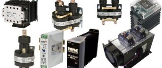
USB connectors
Manufacturers produce different types of connectors in terms of mounting and number of contacts. You can find out exactly what is faulty in your device only after opening it. New connectors are sold in radio stores and stores selling spare parts for telephones individually. It is best to buy a whole set of connectors from an online store, for example, AliExpress. Sellers sell the most popular types in whole packs, so it’s better to buy in bulk, especially if you plan to continue doing such repairs.
Tools
Actually, to replace USB, we need a soldering iron or soldering station itself. Lukey 702 and similar analogues are perfect. You can get by with just one soldering iron, but more on that below. You may also need pliers and wire cutters if you do not have the connector required for the body contacts. You also need the simplest tweezers to remove parts.
Consumables
Thermal tape (or aluminum), desoldering braid, flux (simple RMA223 will do), PIC solder, and also Rose alloy. And a cleaning agent (for example, galosh gasoline, isopropyl alcohol or FLUX OFF).
Classification and pinout
Connectors are usually classified by type, there are only two of them:
- A is a plug connected to the female socket installed on the PC system board or USB hub. Using this type of connection, you can connect a USB flash drive, keyboard, mouse, etc. These connections are fully compatible between the initial version and the second generation. With the latest modification, compatibility is partial, that is, devices and cables from earlier versions can be connected to third-generation sockets, but not vice versa.
Type A connectors - B – plug for connecting to a socket installed on a peripheral device, for example, a printer. The dimensions of the classic type B do not allow it to be used for connecting small-sized devices (for example, tablets, mobile phones, digital cameras, etc.). To correct the situation, two standard reduced modifications of type B were adopted: mini and micro USB.
Note that such convectors are compatible only between earlier modifications.
Various Type B Connector Models
In addition, there are extension cables for the ports of this interface. At one end there is a type A plug, and at the other there is a socket for it, that is, in fact, a “female” - “male” connection. Such cords can be very useful, for example, to connect a flash drive without crawling under the table to the system unit.
USB Extension Cable
Now let's look at how contacts are wired for each of the types listed above.
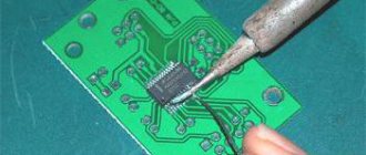
Soldering the connector with a soldering iron
The following micro USB replacement method is designed for a more careful and slower removal. In general, the principle itself is very simple. You can change the connector with one soldering iron without worrying about the board overheating. The main task is to warm up the connector itself with a soldering iron. But the temperature of the soldering iron itself may simply not be enough due to its area. You need to add solder to the connector.
Solder the entire connector
Of course, this can be done using regular lead solder, but maintaining its melting temperature is more difficult, so it is better to use low-temperature alloys such as Rose or Wood.
It is best to use Rose as it is less toxic. Such alloys only need to be desoldered, but not soldered into parts! Rose and Wood are very fragile, they crack quickly and any sharp blow to the soldering area will immediately critically damage the contact. Therefore, after soldering, these alloys must be completely removed from the board and parts and only soldered with them, and not soldered into the board.
Step-by-step soldering process with a soldering iron
Before starting soldering, apply flux to the broken connector. Then we add a couple of rose alloy fonts. We solder both body and contact connections with this alloy. The most important thing is that you don’t need to press, just apply a superficial drop along the connector. If you press, then the part that is already low-temperature will begin to desolder and because of this there is a high risk of tearing off the entire connector immediately with the contacts. We also carefully solder the contacts with a drop.
You need to desolder the connector from the contact side. The contacts themselves are more difficult to tin well, so they produce a higher temperature alloy. Because of this, it is necessary to start heating them from the contacts, and the rest of the heat will be enough for the body since there is a lot of Rose there and the melting point is significantly lower, about 110-120 ° C. We place the soldering iron on the contacts and the connector itself will begin to float out of the board.
These solder residues must be completely cleaned from the board. It is no longer possible to solder a new connector with this alloy. Any mechanical impact and soldering area will immediately become covered with microcracks, which in turn will immediately lead to separation.
Using braid, we clean the board. This is not so difficult to do due to the lower temperature, add flux and the board is clean in a couple of passes.
The board is completely ready for a new part, and we are already soldering with regular solder.
Pros and cons of the method
Pros - you can do this job with one soldering iron without a hair dryer and solder back any other connector. The disadvantages are a larger number of consumables, as well as a high risk of tracks breaking during dismantling.
USB 2.0 connector pinout (types A and B)
Since the physical plugs and sockets of early versions 1.1 and 2.0 do not differ from each other, we will present the wiring of the latter.
Figure 6. Wiring the plug and socket of type A connector
Designation:
- A – nest.
- B – plug.
- 1 – power supply +5.0 V.
- 2 and 3 signal wires.
- 4 – mass.
In the figure, the coloring of the contacts is shown according to the colors of the wire, and corresponds to the accepted specification.
Now let's look at the wiring of the classic socket B.
Wiring of plug and socket type B
Designation:
- A – plug connected to the socket on peripheral devices.
- B – socket on a peripheral device.
- 1 – power contact (+5 V).
- 2 and 3 – signal contacts.
- 4 – ground wire contact.
The colors of the contacts correspond to the accepted colors of the wires in the cord.
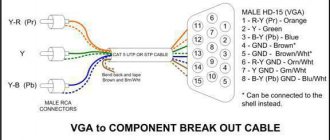
Pinout diagrams for charging tablets
Almost any tablet computer requires a large current to charge - 2 times more than a smartphone, and charging through the mini/micro-USB socket in many tablets is simply not provided by the manufacturer. After all, even USB 3.0 will not provide more than 0.9 amperes. Therefore, a separate nest (often round type) is placed. But it can also be adapted to a powerful USB power source if you solder an adapter like this.
Useful: Cooler pinout: connecting 3 pin and 4 pin fans
The abbreviation “USB” carries an abbreviated designation, which in its entirety reads as “Universal Series Bus” - a universal serial bus, thanks to the use of which high-speed digital data exchange is carried out.
The versatility of the USB interface is noted:
- low power consumption;
- unification of cables and connectors;
- simple logging of data exchange;
- high level of functionality;
- Wide support for drivers for various devices.
USB 3.0 pinout (types A and B)
In the third generation, peripheral devices are connected via 10 (9 if there is no shielding braid) wires; accordingly, the number of contacts is also increased. But they are located in such a way that it is possible to connect devices of earlier generations. That is, the +5.0 V contacts, GND, D+ and D-, are located in the same way as in the previous version. The wiring for Type A socket is shown in the figure below.
Figure 8. Pinout of Type A connector in USB 3.0
Designation:
- A – plug.
- B – nest.
- 1, 2, 3, 4 – connectors fully correspond to the pinout of the plug for version 2.0 (see B in Fig. 6), the colors of the wires also match.
- 5 (SS_TX-) and 6 (SS_TX+) connectors for data transmission wires via the SUPER_SPEED protocol.
- 7 – ground (GND) for signal wires.
- 8 (SS_RX-) and 9 (SS_RX+) connectors for data receiving wires using the SUPER_SPEED protocol.
The colors in the figure correspond to those generally accepted for this standard.
As mentioned above, a plug from an earlier model can be inserted into the socket of this port; accordingly, the throughput will decrease. As for the plug of the third generation of the universal bus, it is impossible to insert it into the sockets of the early release.
Now let's look at the pinout for the type B socket. Unlike the previous type, such a socket is incompatible with any plug of earlier versions.
Wiring USB 3.0 type B
Designations:
A and B are plug and socket, respectively.
Digital signatures for contacts correspond to the description in Figure 8.
The color is as close as possible to the color markings of the wires in the cord.
Cleaning after soldering
After any soldering, it is advisable to clean the soldering area. This is necessary to 100% eliminate corrosion from flux (if you were using inexpensive flux). And also for beauty, so that the soldering area is clean.
Tools used
Galosh gasoline is excellent for cleaning soldering areas. You can clean it with a regular brush, cotton swabs or disks, as well as regular cotton wool.
Nuances when cleaning
There are often microphones near micro USB connectors. When cleaning, do not forget about this, because if flux or a cleaning agent with flux residues gets on the microphone membrane, it will no longer work at all and the microphone will have to be replaced.
Micro USB connector pinout
To begin with, we present the wiring for this specification.
Micro USB v 2.0 connector wiring
As can be seen from the figure, this is a 5 pin connection; both the plug (A) and socket (B) have four contacts. Their purpose and digital and color designation correspond to the accepted standard, which was given above.
Description of the micro USB connector for version 3.0.
For this connection, a characteristically shaped 10 pin connector is used. In fact, it consists of two parts of 5 pin each, and one of them fully corresponds to the previous version of the interface. This implementation is somewhat confusing, especially considering the incompatibility of these types. Probably, the developers planned to make it possible to work with connectors of earlier modifications, but subsequently abandoned this idea or have not yet implemented it.
MicroUSB connector layout for version 3.0
The figure shows the pinout of the plug (A) and the appearance of the micro USB socket (B).
Contacts 1 to 5 fully correspond to the second generation micro connector, the purpose of the other contacts is as follows:
- 6 and 7 – data transmission via high-speed protocol (SS_TX- and SS_TX+, respectively).
- 8 – mass for high-speed information channels.
- 9 and 10 – data reception via high-speed protocol (SS_RX- and SS_RX+, respectively).
How to remake a plug with your own hands
Just take any 220V/5V charging adapter and cut off the USB connector from it. The cut end is completely freed from the shield while the remaining four wires are stripped and tinned. Now we take a cable with a USB connector of the desired type, after which we also cut off the excess from it and carry out the same procedure. Now all that remains is to simply solder the wires together according to the diagram, after which each connection is insulated separately. The resulting case is wrapped on top with electrical tape or tape. You can fill it with hot glue - also a normal option.
Bonus: all other connectors (sockets) for mobile phones and their pinouts are available in a single large table -
Mini USB pinout
This connection option is used only in early versions of the interface; in the third generation this type is not used.
Mini USB connector pinout
As you can see, the wiring of the plug and socket is almost identical to the micro USB, respectively, the color scheme of the wires and the contact numbers are also the same. Actually, the differences are only in shape and size.
In this article we have presented only standard types of connections; many manufacturers of digital equipment practice introducing their own standards; there you can find connectors for 7 pin, 8 pin, etc. This introduces certain difficulties, especially when the question arises of finding a charger for a mobile phone. It should also be noted that products are in no hurry to tell how the USB pinout is done in such contactors. But, as a rule, this information is easy to find on thematic forums.
Bottom line
We examined in detail several methods for replacing the USB connector on mobile devices yourself. It may seem difficult at first glance, but everything comes with experience. The main rules are that you don’t need to rush, tear out the connector from the board prematurely, and don’t fry the board.
The methods described above are also suitable for replacing micro USB on a tablet yourself; there are no fundamental differences.
Cost of work
In various service centers, the price for this work on average starts from 500 rubles. The price may be higher due to complex disassembly (for example, unsticking the display module, the service takes responsibility), guarantees after the replacement procedure, as well as the complexity of the work performed (torn off tracks and pieces of the board).