Almost everyone is well aware of three-phase electric motors; they are widely used in industry and allow solving a wide variety of problems. And we are accustomed to consider the principle of obtaining alternating current as a physical quantity using the example of the same three-phase asynchronous generators. But what to do in domestic conditions, where there is only one phase? Craftsmen have learned how to connect three-phase electrical machines, but this is not necessary. In practice, a single-phase asynchronous electric motor has long been used, which can perform all its functions even in a home AC network.
Design features
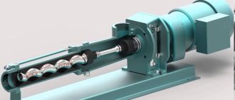
If we compare a single-phase electric motor with other electric machines, then structurally it also consists of a movable and stationary element - a stator and a rotor. The stator, due to the flow of electric current through its windings, creates a magnetic field that interacts with the rotor. As a result of electromagnetic interaction, the rotor is rotated.
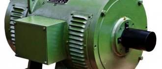
Rice. 1. Design of single-phase asynchronous electric motor
However, everything is not as simple as it might seem at first glance; if you removed the extra two windings from a conventional three-phase electric motor and plugged it into an outlet, rotation would not start. The motor simply does not have enough torque to rotate the rotor. Therefore, the design of a single-phase asynchronous electric motor has a number of features.
Rotor
The rotor of a single-phase electric motor is the same metal shaft, which is equipped with a winding. A ferromagnetic frame made of laminated steel is assembled on the shaft and grooves are made along its outer surface. Rods made of copper or aluminum are installed in the grooves on the rotor shaft, which act as a winding that conducts electric current. At the ends, the rods are connected by two rings, due to this design it is also called a squirrel cage.
When an electromagnetic flux from the stator is applied to the short-circuited windings of the rotor, current begins to flow in the squirrel cage. A ferromagnetic insert on the shaft helps to enhance the flux passing through it. However, not all models have a magnetic conductor; in some it is made of non-magnetic alloys.
Stator
The stator design in a single-phase electric motor has the same composition as in most electrical machines:
- metal case;
- a magnetic circuit made of ferromagnetic material installed inside;
- stator winding, represented by copper conductors.
The stator windings of such an electric motor are divided into two - the main winding, which is also the working winding, through which the load is constantly circulated, and the starting winding, which is activated only at the time of start-up. Both windings of a single-phase motor are located at an angle of 90° relative to each other. This design makes them similar to two-phase electric motors, which also use two windings.
But their volume, relative to the entire space of the asynchronous motor, is different; the main one is only 2/3 of the total number of slots, and the starting windings occupy 1/3.
Operating principle
In our school physics lessons, we were all shown experiments with a wire frame placed in the field of a permanent magnet. If a current is passed through the frame, then the Ampere forces will act on the conductors on the right and left sides of the frame, creating a torque, and the frame with the current will rotate until it takes a position in which the acting forces balance each other.
If you make the field rotate, the current frame will rotate with it. The operation of a synchronous electric motor is based on this principle. A frame with magnets is an analogue of an electric motor. A rotating frame with current is the rotor. Fixed magnets - stator.
Principle of operation
The operating principle of a single-phase asynchronous electric motor is to create a pulsating magnetic flux from the flow of electric current through the main stator winding, if we consider the option of starting from an auxiliary turn. Thus, we will consider connecting a single-phase motor to the network using the example of one turn.
Rice. 2. The principle of magnetic flux formation in the stator
As you can see in the figure above, alternating electric current, flowing through a conductor, according to the gimlet rule, creates concentric magnetic fluxes. When the maximum of the sinusoid appears, the magnetic flux will also reach its maximum. However, in a single-phase alternating voltage network, the current changes its direction of movement in a coil with a frequency of 50 Hz. This means that as soon as the curve crosses the x-axis, the current will flow through the winding in the opposite direction and the magnetic flux created by it will receive opposite poles and the direction of the resulting vector:
Rice. 3. Formation of reverse flow
From a physical point of view, both flows are equivalent, so changing them at intervals of 100 times per second will give a zero result when added. The forward magnetic flux will be equal to the reverse one:
Fpr = Fobr
This means that if the rotor of an electric motor is in such a field, it will not rotate. The magnetic flux will change 100 times a minute, and the squirrel-cage rotor will simply hum, remaining in place. However, the situation will change radically if there is an impulse to the initial movement. In this case, slipping will appear, which will lead to constant rotation of the shaft:
Spr = (n1 - n2) / n1, where
- n1 – rotation frequency of the magnetic field of a single-phase electric motor;
- n2 – rotor speed of the asynchronous electric motor;
- S is the slip value of a single-phase induction motor.
When the magnetic flux changes, the direction of rotation and the fields of the stator and rotor of the electric motor will coincide, so the slip will receive a different expression for calculation:
Sobr = (n1 - ( - n2)) / n1, where
The alternating intersection of the rods with magnetic fluxes of different directions will create an EMF in them, which will generate an electric current in the rotor and a response magnetic flux. And it, in turn, will also interact with the stator field of a single-phase electric motor, as shown in the figure below.
Rice. 4. Obtaining EMF in the rotor
As you can see, to connect a three-phase electric motor, you just need to apply voltage to it, but this option will not work with a single-phase one.
To start the motor, a primary impulse is required, which in practice can be obtained by:
- spinning the shaft manually;
- short-term introduction of the trigger coil;
- splitting of the magnetic field by a short-circuited circuit.
Of the above methods, today the first is used only in laboratory experiments; it has fallen out of practical use due to the risk of injury to the operator.
Three-phase synchronous motor
Now we need to force the stationary stator to create a rotating magnetic field.
First, let's replace the permanent magnets with current-carrying coils and stator windings. A coil carrying current creates the same magnetic field as a magnet. Let's place not one magnet coil on the stator, but three, rotating them 120 degrees relative to each other. Let's apply alternating current to these windings with a phase shift of 120 degrees. This is exactly how the phases are shifted in a three-phase network.
The resulting magnetic field is the result of the vector addition of three fields. The total vector of magnetic induction will rotate with the frequency of alternating current. In one period, the magnetic field created by the stator of a three-phase motor makes a full revolution. The rotor, which is similar to a coil carrying current, rotates along with the magnetic field of the stator at the same speed. Thus, the rotor of a synchronous motor rotates at the frequency of the AC supply current.
Synchronous motors have the best characteristics, develop maximum power and provide high efficiency. However, there is a heavy rotor with windings, which is difficult to balance. Current must be supplied to the rotor windings, and this requires the use of an extremely unreliable brush assembly. In general, a synchronous motor is good, but it is complex, expensive and not very reliable.
Connection diagrams
To obtain the basic rotational impulse, various connection schemes can be used. Over time, some of them lost their relevance and were replaced by more progressive ones, so next we will look at the most effective ones, which are still used today.
With starting resistance
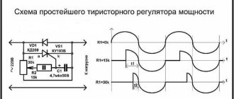
Since the resistance of the windings in induction motors has a complex form, the magnetic flux vector can be easily shifted if resistance is added to the starting winding. The presence of an active component will give the required shift angle between the working coils of a single-phase electric motor and the starting coil, from 15° to 50°, which will provide the difference for the initial rotation.
Rice. 5. Circuit with starting resistance
With capacitor start
Unlike the previous method, in a circuit with a capacitor start of an electric motor, a capacitive element is used, which allows you to shift the electrical quantities in the main and starting coils by 90°, providing maximum force.
Rice. 6. Capacitor start circuit
In practice, the starting capacitor along with the additional winding is introduced by the start button simultaneously with the supply of the main power. The start button is designed in such a way that contact Cn is returned by a spring to its original position immediately after the end of the capacitor start.
Split pole
Unlike capacitor motors, this starting method requires the presence of a special design of the stator magnetic circuit. In this case, each pole is divided into two, one of which is equipped with a short-circuited coil that changes the characteristics of the magnetic flux.
Rice. 7. Shaded pole circuit
A significant disadvantage of this method of starting a single-phase electric motor is the constant loss of power and a decrease in the efficiency of the motor. Therefore, it is used only in electric machines up to 100 kW.
Types of electrical machine repairs
To prevent malfunctions, maintenance and scheduled repairs of electrical equipment should be carried out according to the approved schedule.
Electrical machine repairs are divided into maintenance (MOT), current, medium and major repairs. The scope of work in each of these types of work is determined by the “Standard Regulations on Maintenance and Repair (MRO) of Electrical Equipment”.
Maintenance
This is to maintain equipment in working order between scheduled repairs. Carried out by maintenance and operational maintenance personnel.
Provides for the following types of work:
- inspection;
- heating check;
- wiping off dirt;
- insulation check;
- identifying faults and eliminating them.
It is carried out according to the approved schedule and during downtime - lunch break, adjustment, tool change.
Maintenance
Maintained in working condition until repaired. Produced on site or in a workshop. Includes:
- complex of maintenance works;
- replacement of failed components - bearings and couplings;
- adjustment and checking of alignment.
Medium renovation
For problems that cannot be eliminated during routine repairs, a medium repair is performed. This produces:
- complete disassembly;
- if necessary, replace bearings;
- repair of housing and shaft;
- impregnation of windings with varnish;
- insulation or replacement of leads
Medium repairs are carried out in specialized workshops and enterprises.
Major renovation
Complete restoration of characteristics and parameters. In addition to the complex of medium repair works, the windings of the electric machine are replaced or repaired.
Electric motor malfunctions are easier to prevent than to eliminate their consequences. To do this, it is necessary to carry out a set of work on servicing the mechanism in a timely manner and equip it with the necessary protective devices.
{SOURCE}
Tags: automatic, sconce, type, choice, switch, engine, house, , capacity, replacement, insulation, like, kW, capacitor, design, , magnet, power, voltage, nominal, connection, rule, check, wire, manufacturer, start, , work, size, calculation, resistor, resonance, relay, repair, row, connection, term, circuit, type, current, , shield, effect
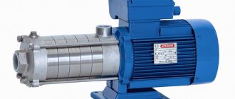
Application area
Single-phase electric motors are widely used in household appliances or industrial small-scale mechanization devices. They cover relatively low-power single-phase equipment that is powered by 220V.
These are various machines for processing wood, metal, plastic, etc. Single-phase electric motors are also used in agricultural installations for mixing grains, making concrete, etc. In everyday life, they are used in some models of microwave ovens, hoods, washing machines and coolers powered by a single-phase source.